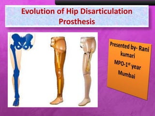
Evolution of Hip Disarticulation
Prosthesis
Rani kumari
AIIPMR,
Mumbai
INTRODUCTION
• Hip disarticulation
is the surgical
removal of the
lower limb
through the hip
joint.
• 2% of all
amputations are
at the hip
disarticulation
level.
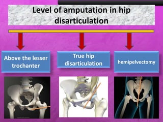
Level of amputation in hip
disarticulation
Above the lesser
trochanter
True hip
disarticulation hemipelvectomy
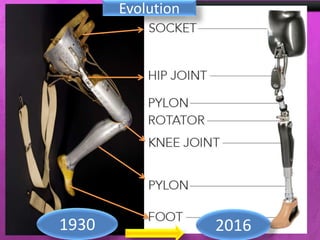
Evolution
1930 2016
Evolution of hip Disarticulation
Prosthesis
Tilting-table Prosthesis (1940)
Saucer-type Prosthesis(1957)
Canadian Hip Disarticulation Prosthesis(1954)
UCLA Anatomical H.D. Prosthesis(1980)
U.S. Navy Hydraulic Prosthesis(1945)
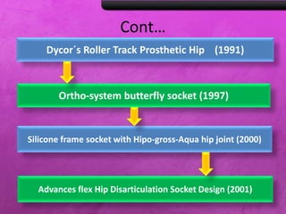
Cont…
Advances flex Hip Disarticulation Socket Design (2001)
Silicone frame socket with Hipo-gross-Aqua hip joint (2000)
Dycor´s Roller Track Prosthetic Hip (1991)
Ortho-system butterfly socket (1997)
Cont…
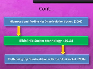
Bikini Hip Socket technology (2013)
Re-Defining Hip Disarticulation with the Bikini Socket (2016)
Glenrose Semi-flexible Hip Disarticulation Socket (2005)
Socker type
Tilting table
prosthesis
Canadian hip
prosthesis
US navy
prosthesis
UCLA
anatomical
1940-1980
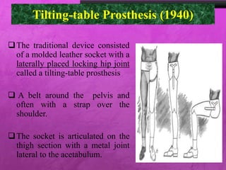
Tilting-table Prosthesis (1940)
The traditional device consisted
of a molded leather socket with a
laterally placed locking hip joint
called a tilting-table prosthesis
 A belt around the pelvis and
often with a strap over the
shoulder.
The socket is articulated on the
thigh section with a metal joint
lateral to the acetabulum.
 Because it is extremely difficult to make a hip
joint strong enough to bear the entire load, contact
between the socket and the medial edge of the
thigh section is essential in weight-bearing, and
this is equally important when a lock is used.
 Without a lock, the wearer has little control over
the limb, most of the stability during the stance
phase being afforded by friction between the
socket and the thigh section.
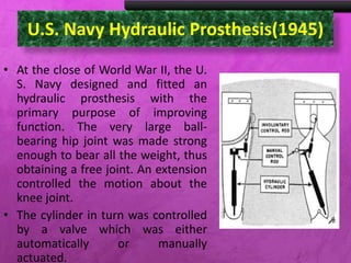
U.S. Navy Hydraulic Prosthesis(1945)
• At the close of World War II, the U.
S. Navy designed and fitted an
hydraulic prosthesis with the
primary purpose of improving
function. The very large ball-
bearing hip joint was made strong
enough to bear all the weight, thus
obtaining a free joint. An extension
controlled the motion about the
knee joint.
• The cylinder in turn was controlled
by a valve which was either
automatically or manually
actuated.
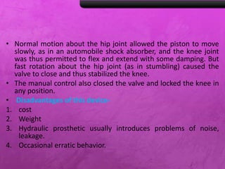
• Normal motion about the hip joint allowed the piston to move
slowly, as in an automobile shock absorber, and the knee joint
was thus permitted to flex and extend with some damping. But
fast rotation about the hip joint (as in stumbling) caused the
valve to close and thus stabilized the knee.
• The manual control also closed the valve and locked the knee in
any position.
• Disadvantages of this device-
1. cost
2. Weight
3. Hydraulic prosthetic usually introduces problems of noise,
leakage.
4. Occasional erratic behavior.
Canadian Hip Disarticulation
Prosthesis(1954)
In order to achieve
simplicity in assembly and
to increase mechanical
rigidity, the forward link
was lengthened and made
strong enough to support
all the main loads.
The rear link thus acted
only as a guide and could
be made light and
adjustable.
Cont….
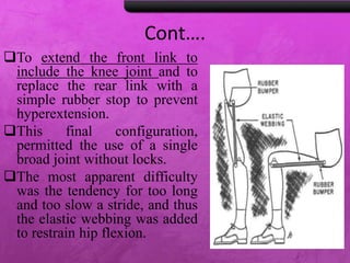
To extend the front link to
include the knee joint and to
replace the rear link with a
simple rubber stop to prevent
hyperextension.
This final configuration,
permitted the use of a single
broad joint without locks.
The most apparent difficulty
was the tendency for too long
and too slow a stride, and thus
the elastic webbing was added
to restrain hip flexion.
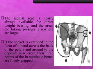
The ischial seat is nearly
always available for direct
weight bearing, and the areas
for taking pressure elsewhere
are large.
If the socket is extended in the
form of a band across the back
of the pelvis and around to the
opposite iliac crest, then three
points of the in nominate bones
are firmly gripped.
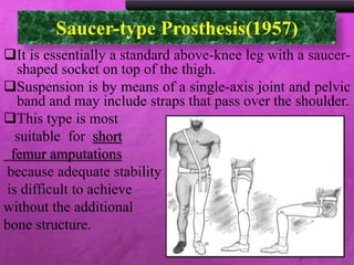
Saucer-type Prosthesis(1957)
It is essentially a standard above-knee leg with a saucer-
shaped socket on top of the thigh.
Suspension is by means of a single-axis joint and pelvic
band and may include straps that pass over the shoulder.
This type is most
suitable for short
femur amputations
because adequate stability
is difficult to achieve
without the additional
bone structure.
Cont…
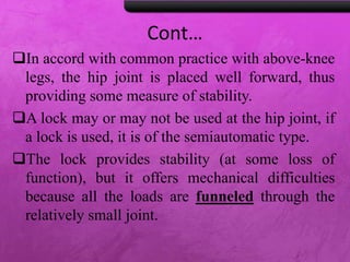
In accord with common practice with above-knee
legs, the hip joint is placed well forward, thus
providing some measure of stability.
A lock may or may not be used at the hip joint, if
a lock is used, it is of the semiautomatic type.
The lock provides stability (at some loss of
function), but it offers mechanical difficulties
because all the loads are funneled through the
relatively small joint.
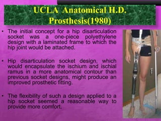
UCLA Anatomical H.D.
Prosthesis(1980)
• The initial concept for a hip disarticulation
socket was a one-piece polyethylene
design with a laminated frame to which the
hip joint would be attached.
• Hip disarticulation socket design, which
would encapsulate the ischium and ischial
ramus in a more anatomical contour than
previous socket designs, might produce an
improved prosthetic fitting.
• The flexibility of such a design applied to a
hip socket seemed a reasonable way to
provide more comfort.
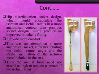
Cont……
Hip disarticulation socket design,
which would encapsulate the
ischium and ischial ramus in a more
anatomical contour than previous
socket designs, might produce an
improved prosthetic fitting.
 Provide more comfort.
This was an attempt at a more
anatomical socket, contours detailing
the ischial ramus angle and the
medial inclination of the ischium
were included in the cast.
Thus the medial brim need not
extend as high or contain as much of
the ischial ramus.
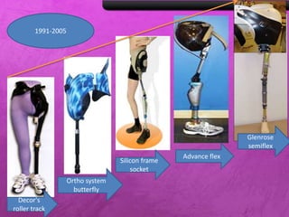
Decor's
roller track
Ortho system
butterfly
Silicon frame
socket
Advance flex
Glenrose
semiflex
1991-2005
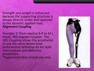
Dycor´s Roller Track Prosthetic
Hip (1997)
• Hip Circumference at trocanteric level
Extra Small 27"
Small 32"
Medium 38"
Large 45"
Extra Large 52"
Positioning the hip joint in the center of the socket rather than
anteriorly enhances toe clearance during swing phase because the
knee swings forward and upward rather than forward and
downward.
Hip rotation occurs through a laterally mounted single axis joint with
extension stop and flexion bias.
Vertical loads are supported by a wheel attached to the thigh pylon
component trans versing a hemispherical track built into the socket.
Strength and weight is enhanced
because the supporting structure is
always directly under and opposed
to the dynamic applied load.
Alignment Coupling
Provides 1" from neutral A-P to M-L
travel, 360 degrees rotation. The
ADL Coupling allows the prosthetist
to use the same below knee
endoskeletal definitive kit for both
intermediate and definitive
prosthetics.
*Supervised intra-clinical use only
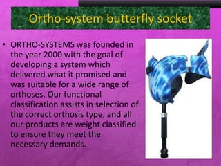
Ortho-system butterfly socket
• ORTHO-SYSTEMS was founded
in the year 2000 with the goal
of developing a system which
delivered what it promised and
was suitable for a wide range of
orthoses. Our functional
classification assists in selection
of the correct orthosis type, and
all our products are weight
classified to ensure they meet
the necessary demands.
Cont…
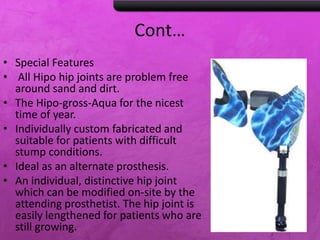
• Special Features
• All Hipo hip joints are problem free
around sand and dirt.
• The Hipo-gross-Aqua for the nicest
time of year.
• Individually custom fabricated and
suitable for patients with difficult
stump conditions.
• Ideal as an alternate prosthesis.
• An individual, distinctive hip joint
which can be modified on-site by the
attending prosthetist. The hip joint is
easily lengthened for patients who are
still growing.
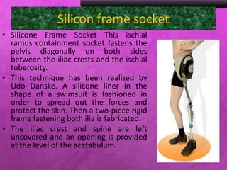
Silicon frame socket
• Silicone Frame Socket This ischial
ramus containment socket fastens
the pelvis diagonally on both sides
between the iliac crests and the
ischial tuberosity.
• This technique has been realized by
Udo Danske. A silicone liner in the
shape of a swimsuit is fashioned in
order to spread out the forces and
protect the skin. Then a two-piece
rigid frame fastening both ilia is
fabricated.
• The iliac crest and spine are left
uncovered and an opening is
provided at the level of the
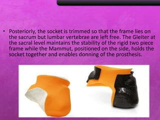
• Posteriorly, the socket is trimmed so that the frame lies on
the sacrum but lumbar vertebrae are left free. The Gleiter at
the sacral level maintains the stability of the rigid two piece
frame while the Mammut, positioned on the side, holds the
socket together and enables donning of the prosthesis.
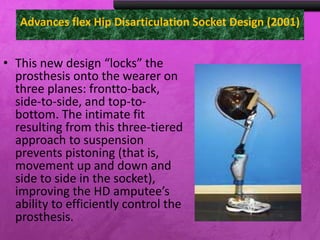
Advances flex Hip Disarticulation Socket Design (2001)
• This new design “locks” the
prosthesis onto the wearer on
three planes: frontto-back,
side-to-side, and top-to-
bottom. The intimate fit
resulting from this three-tiered
approach to suspension
prevents pistoning (that is,
movement up and down and
side to side in the socket),
improving the HD amputee’s
ability to efficiently control the
prosthesis.
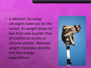
• n addition, by using
ultralight materials for the
socket, its weight drops to
less than one-quarter that
of traditional acrylic or
silicone sockets. Reduced
weight translates directly
into less energy
expenditure.
Glenrose semiflexible socket design
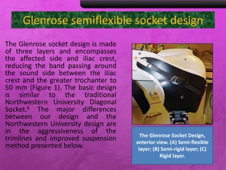
The Glenrose socket design is made
of three layers and encompasses
the affected side and iliac crest,
reducing the band passing around
the sound side between the iliac
crest and the greater trochanter to
50 mm (Figure 1). The basic design
is similar to the traditional
Northwestern University Diagonal
Socket.6 The major differences
between our design and the
Northwestern University design are
in the aggressiveness of the
trimlines and improved suspension
method presented below.
The Glenrose Socket Design,
anterior view. (A) Semi-flexible
layer; (B) Semi-rigid layer; (C)
Rigid layer.
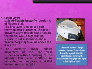
• Socket Layers
1. Semi-flexible butterfly (portion A
of Figures 1-3).
The first layer is made of a soft
thermoplastic elastomer. This layer
provides a soft flexible transition on
the medial wall, a high friction
surface to aid suspension, and a
flexible, forgiving trimline above the
iliac crest.
• The butterfly shape allows
movement of the iliac crest
suspension without buckling of the
material. This piece is difficult to
fabricate and requires a skilled
technician to accomplish.
Glenrose Socket Design
interior, viewed from above
from the sound side. (A)
Semiflexible layer with
butterfly shape; (B) Semi-rigid
polyethylene layer.
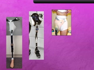
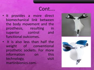
Bikini Hip Socket technology
• Published on Oct 25, 2013
• The latest prosthetic socket
interface advancements radically
changes life for individuals with
hip
disarticulation/hemipelvectomy
levels of amputation. Developed
by Jay Martin, CP, FAAOP, the
patented Bikini Hip Socket
technology effectively distributes
mechanical forces through
compliant materials, providing
the most comfortable interface
Cont….
• It provides a more direct
biomechanical link between
the body movement and the
prosthesis, resulting in
superior control and
functional outcomes.
• It is also less than half the
weight of conventional
prosthetic sockets. For more
information on this
technology, visit
martinbionics.com.
Biomechanics
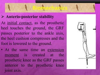
 Anterio-posterior stability
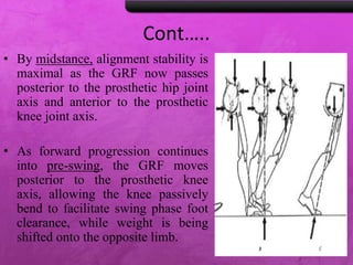
At initial contact, as the prosthetic
heel touches the ground, the GRF
passes posterior to the ankle axis,
the heel cushion compresses and the
foot is lowered to the ground.
• At the same time an extension
moment is created at the
prosthetic knee as the GRF passes
anterior to the prosthetic knee
joint axis.
Cont…..
• By midstance, alignment stability is
maximal as the GRF now passes
posterior to the prosthetic hip joint
axis and anterior to the prosthetic
knee joint axis.
• As forward progression continues
into pre-swing, the GRF moves
posterior to the prosthetic knee
axis, allowing the knee passively
bend to facilitate swing phase foot
clearance, while weight is being
shifted onto the opposite limb.
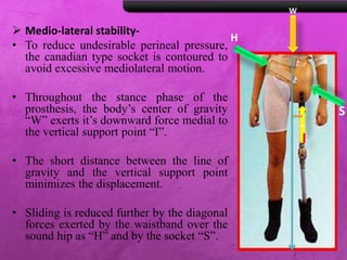
 Medio-lateral stability-
• To reduce undesirable perineal pressure,
the canadian type socket is contoured to
avoid excessive mediolateral motion.
• Throughout the stance phase of the
prosthesis, the body’s center of gravity
“W” exerts it’s downward force medial to
the vertical support point “I”.
• The short distance between the line of
gravity and the vertical support point
minimizes the displacement.
• Sliding is reduced further by the diagonal
forces exerted by the waistband over the
sound hip as “H” and by the socket “S”.
I
W
H
S
I
Stability in the sagittal plane-
 Hip joint is located in front of the weight line
,creating an extension moment of force .
 Knee joint is located behind the weight line so
that gravity tend to extend the knee.
 Reference line through the hip and knee joint
should pass at least one inch behind the heel.
Stability in the frontal plane-
 Instability in the frontal plane is reduced by
aligning the prosthesis with a narrow base,
approximately 3 inch between heel centers.
 A wider base would force the amputee to bend
his trunk laterally in order to move his center of
gravity over the prosthesis.
Evolution of hip disarticulation prosthesis