ENG. ALI UDAY HAROBEY | HVAC DESIGN ENGINEER ESP • PRESSURE LOSS • FAN SELECTION
H V A C A I R - S I D E D E S I G N
From Duct Design
to Fan Selection
Understanding ESP, Pressure Loss & Fan Curves
PRACTICAL HVAC ENGINEERING
AHU FAN
FILTER
120 Pa
COIL
150 Pa
DUCT
70 Pa
FITTINGS
55 Pa
TERMINAL
70 Pa
Design duty • 7,500 CFM @ ≈ 500 Pa
1
ENG. ALI UDAY HAROBEY – HVAC DESIGN ENGINEER
ENG. ALI UDAY HAROBEY | HVAC DESIGN ENGINEER ESP • PRESSURE LOSS • FAN SELECTION
01 — WHY FAN SELECTI O N MATTERS
A fan is not selected by CFM alone.
The system resistance is part of the duty point.
AIRFLOW
7,500
CFM
SYSTEM RESISTANCE
≈ 500
Pa
DUTY POINT
Q + ΔP
required
VERIFY
η + motor + sound
after selection
UNDERSIZED
Airflow falls below design
• poor space delivery
• comfort complaints
CORRECT
Meets duty at a stable
operating region
• efficient • controllable
OVERSIZED
High noise / throttling
• poor efficiency
• unnecessary cost
Engineering idea: the fan must overcome the resistance of the actual air path at the required airflow.
2
ENG. ALI UDAY HAROBEY | HVAC DESIGN ENGINEER ESP • PRESSURE LOSS • FAN SELECTION
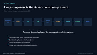
02 — THE AIR PATH
Every component in the air path consumes pressure.
Follow the actual flow path before you calculate ESP.
OUTDOOR /
AHU
FILTER COIL FAN
SUPPLY
DUCT
FITTINGS DAMPER TERMINAL SPACE
Pressure demand builds as the air moves through the system.
Component data: filters, coils, dampers, terminals
Duct data: length, size, velocity, roughness
Fittings: local losses and transitions
Critical path: the most resistant required branch
3
ENG. ALI UDAY HAROBEY | HVAC DESIGN ENGINEER ESP • PRESSURE LOSS • FAN SELECTION
03 — PRESSURE BASI C S
Static pressure, velocity pressure and total pressure
Use the right pressure term for the job.
AIRFLOW
Pᵗ = Pˢ + Pᵛ
Pˢ = Static pressure
Pᵛ = Velocity pressure
Pᵗ = Total pressure
4
ENG. ALI UDAY HAROBEY | HVAC DESIGN ENGINEER ESP • PRESSURE LOSS • FAN SELECTION
04 — WHAT IS ESP?
External Static Pressure (ESP)
The definition must match the equipment rating convention.
ESP is the pressure capability required to
overcome the external system resistance
connected to the fan.
EXTERNAL SYSTEM
Supply / return ductwork
Fittings and dampers
Terminal pressure drop
Other connected components
FAN
DUCT FITTINGS DAMPER TERMINAL
Design rule: align your system-pressure calculation with the manufacturer’s
fan/AHU pressure-rating convention.
5
ENG. ALI UDAY HAROBEY | HVAC DESIGN ENGINEER ESP • PRESSURE LOSS • FAN SELECTION
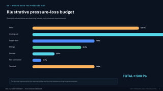
05 — WHERE DOES THE PRESSURE GO?
Illustrative pressure-loss budget
Example values below are teaching values, not universal requirements.
Filter 120 Pa
Cooling coil
Supply duct 70 Pa
Fittings 55 Pa
Damper 25 Pa
Flex connection 10 Pa
Terminal 70 Pa
TOTAL ≈ 500 Pa
The fan duty is governed by the required airflow and the total resistance along the governing path.
6
ENG. ALI UDAY HAROBEY | HVAC DESIGN ENGINEER ESP • PRESSURE LOSS • FAN SELECTION
06 — DUCT FRICTI O N
Straight-duct friction is only one part of the system resistance.
A simple design relationship is ΔP = R × L.
ΔP = R × L
ΔP = pressure loss
R = friction rate
L = duct length
Fittings are additional local losses.
STRAIGHT DUCT
ELBOW → LOCAL LOSS
7
ENG. ALI UDAY HAROBEY | HVAC DESIGN ENGINEER ESP • PRESSURE LOSS • FAN SELECTION
07 — FITTINGS & DYNAM I C LOSSES
Pressure loss also comes from changes in flow direction and area.
For local losses, a common model is ΔP = K · (ρV² / 2).
ELBOW
local loss coefficient
BRANCH
local loss coefficient
TRANSITION
local loss coefficient
DAMPER
local loss coefficient
ENTRY / EXIT
local loss coefficient
ΔP = K × (ρV² / 2)
Velocity matters: because the term contains V², higher velocity can increase dynamic pressure quickly.
8
ENG. ALI UDAY HAROBEY | HVAC DESIGN ENGINEER ESP • PRESSURE LOSS • FAN SELECTION
08 — THE AIR TERMIN A L ALSO MATTERS
Terminal pressure drop is part of the air-delivery design.
Pressure is not “free” at the diffuser, grille, or jet nozzle.
DIFFUSER
Pressure drop
Throw / spread
NC / noise
Design target
✓ verified from selection data
GRILLE
Effective area
Face velocity
Pressure drop
Design target
✓ verified from selection data
JET NOZZLE
Throw / penetration
Angle
Pressure drop
Design target
✓ verified from selection data
9
ENG. ALI UDAY HAROBEY | HVAC DESIGN ENGINEER ESP • PRESSURE LOSS • FAN SELECTION
09 — BUI LD THE PRESSURE BUDGET
Think of fan pressure as a finite budget.
Every component spends part of it.
FILTER COIL DUCT FITTINGS DAMPER
FLE
X TERMINAL
0 Pa ≈ 500 Pa
Available fan pressure
A good pressure budget makes it obvious where the system is expensive — and where redesign may pay off.
10
ENG. ALI UDAY HAROBEY | HVAC DESIGN ENGINEER ESP • PRESSURE LOSS • FAN SELECTION
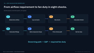
10 — ESP CALCU L AT I O N WORKFLO W
From airflow requirement to fan duty in eight checks.
Use the actual connected system, not a guess.
01
Determine airflow
02
Lay out ducts
03
Size ducts
04
Calculate friction
05
Calculate fittings
06
Add component drops
07
Find critical path
08
Set fan duty
Governing path → ΣΔP → required fan duty
11
ENG. ALI UDAY HAROBEY | HVAC DESIGN ENGINEER ESP • PRESSURE LOSS • FAN SELECTION
11 — FIND THE CRITIC A L PATH
The fan must satisfy the governing branch.
A shorter branch can still be the winner if it has less resistance.
FAN
BRANCH A 250 Pa
BRANCH B 480 Pa
GOVERNING PATH
Branch B
The required fan duty is driven by the required airflow at the highest resistance that must be served.
12
ENG. ALI UDAY HAROBEY | HVAC DESIGN ENGINEER ESP • PRESSURE LOSS • FAN SELECTION
12 — FROM ESP TO FAN DUTY
Turn the pressure budget into a clear selection point.
This is the moment where the system calculation becomes an equipment requirement.
REQUIRED AIRFLOW
7,500
CFM
SYSTEM RESISTANCE
≈ 500
Pa
FAN DUTY
Q @ ΔP
select here
7,500 CFM @ ≈ 500 Pa
FAN OPERATING POINT
13
ENG. ALI UDAY HAROBEY | HVAC DESIGN ENGINEER ESP • PRESSURE LOSS • FAN SELECTION
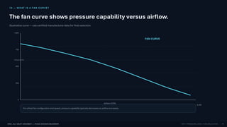
13 — WHAT IS A FAN CURVE?
The fan curve shows pressure capability versus airflow.
Illustrative curve — use certified manufacturer data for final selection.
Airflow (CFM)
Pressure (Pa)
FAN CURVE
0 2,000 4,000 6,000 8,000
0
250
500
750
1,000
For a fixed fan configuration and speed, pressure capability typically decreases as airflow increases.
14
ENG. ALI UDAY HAROBEY | HVAC DESIGN ENGINEER ESP • PRESSURE LOSS • FAN SELECTION
14 — SYSTEM CURVE
System resistance rises approximately with Q² for a fixed system.
That makes airflow increases progressively more expensive in pressure terms.
Airflow (CFM)
System
pressure (Pa)
ΔP ∝ Q²
FIXED SYSTEM
If the system configuration changes, the system curve changes too — for example through dirty filters or damper position.
15
ENG. ALI UDAY HAROBEY | HVAC DESIGN ENGINEER ESP • PRESSURE LOSS • FAN SELECTION
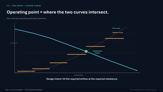
15 — FAN CURVE × SYSTEM CURVE
Operating point = where the two curves intersect.
This is the key visual for practical fan selection.
Airflow (CFM)
Pressure (Pa)
OPERATING
POINT
Fan curve
System curve
Design intent: hit the required airflow at the required resistance.
16
ENG. ALI UDAY HAROBEY | HVAC DESIGN ENGINEER ESP • PRESSURE LOSS • FAN SELECTION
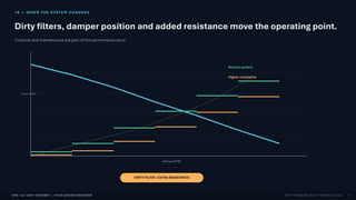
16 — WHEN THE SYSTEM CHANGES
Dirty filters, damper position and added resistance move the operating point.
Controls and maintenance are part of the performance story.
Airflow (CFM)
Pressure (Pa)
Normal system
Higher resistance
DIRTY FILTER / EXTRA RESISTANCE
17
ENG. ALI UDAY HAROBEY | HVAC DESIGN ENGINEER ESP • PRESSURE LOSS • FAN SELECTION
17 — FAN LAWS
Speed changes can strongly change system performance.
Idealized relationships — real equipment still needs manufacturer verification.
FLOW
Q ∝ N
speed
PRESSURE
ΔP ∝ N²
speed²
POWER
P ∝ N³
speed³
Example: speed ↑ 10%
Flow
1.10×
Pressure
1.21×
Power
1.33×
The cubic power relationship is why speed control can have a major energy impact when operating conditions permit.
18
ENG. ALI UDAY HAROBEY | HVAC DESIGN ENGINEER ESP • PRESSURE LOSS • FAN SELECTION
18 — FAN EFFICI E N CY
Meeting duty is not enough — look at where the fan operates.
Efficiency, stability and motor sizing matter.
Airflow (CFM)
Pressure /
Efficiency
PREFERRED REGION
Pressure curve
Efficiency region
Do not force a fan to operate near an unstable or highly inefficient part of its map just to “hit the number.”
19
ENG. ALI UDAY HAROBEY | HVAC DESIGN ENGINEER ESP • PRESSURE LOSS • FAN SELECTION
19 — MOTOR POWER
A quick power estimate ties airflow, pressure and efficiency together.
Use consistent SI units in the equation.
P ≈ Q × ΔP / η
Illustrative example
AIRFLOW
3.54
m³/s
PRESSURE
500
Pa
ASSUMED η
0.62
illustrative
P ≈ 2.9 kW
This is an estimate for teaching — final motor selection includes manufacturer data, service conditions, drive losses and sizing practice.
20
ENG. ALI UDAY HAROBEY | HVAC DESIGN ENGINEER ESP • PRESSURE LOSS • FAN SELECTION
20 — WORKED EXAMPLE
7,500 CFM @ ≈ 500 Pa
Illustrative system: add the pressure drops along the governing path.
Filter 120 Pa
Cooling coil 150 Pa
Supply duct 70 Pa
Fittings 55 Pa
Damper 25 Pa
Flex connection 10 Pa
Terminal 70 Pa
Σ ΔP
≈ 500 Pa
7,500 CFM
FAN DUTY POINT
Final selection must be verified against certified fan performance at the specified operating conditions.
21
ENG. ALI UDAY HAROBEY | HVAC DESIGN ENGINEER ESP • PRESSURE LOSS • FAN SELECTION
21 — FAN SELECT IO N
A practical selection sequence
Choose the fan to satisfy the duty, then verify the whole equipment package.
01
REQUIRED DUTY
Q + ΔP
02
CANDIDATE FAN
catalogue / software
03
OPERATING POINT
curve intersection
04
EFFICIENCY
preferred region
05
MOTOR
power + margin
06
SOUND
NC / dBA
07
CONTROL
VFD / speed
08
VERIFY
manufacturer data
Selection ≠“capacity check” → it is a duty-point + performance + application decision.
22
ENG. ALI UDAY HAROBEY | HVAC DESIGN ENGINEER ESP • PRESSURE LOSS • FAN SELECTION
22 — FAN SELECT IO N CHECKLIS T
Before you sign the selection, verify the full duty.
Use this as a design QA gate.
✓ Required airflow
✓ Required pressure / rating convention
✓ Critical path verified
✓ Filter & coil drops checked
✓ Terminal pressure drop checked
✓ Efficiency checked
✓ Motor power checked
✓ Noise checked
✓ Operating point checked
✓ Control method checked
✓ Manufacturer data verified
Quality control principle: every fan selection should be reproducible from the design calculations and the manufacturer performance data.
23
ENG. ALI UDAY HAROBEY | HVAC DESIGN ENGINEER ESP • PRESSURE LOSS • FAN SELECTION
23 — COMM O N MISTAK ES
Seven ways fan selection goes wrong
The goal is not just a fan that runs — it is a fan that performs the design.
01 SELECTING FROM CFM ONLY
02 IGNORING THE CRITICAL PATH
03 FORGETTING FITTING LOSSES
04 IGNORING DIRTY-FILTER DROP
05 CONFUSING STATIC & TOTAL PRESSURE
06 SELECTING AN INEFFICIENT DUTY POINT
07 IGNORING NOISE / MOTOR POWER
Most fan problems are not caused by the fan alone — they begin in the system definition.
24
ENG. ALI UDAY HAROBEY | HVAC DESIGN ENGINEER ESP • PRESSURE LOSS • FAN SELECTION
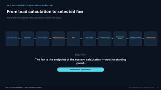
24 — THE COMPLE TE ENGINEER I NG WORKFLO W
From load calculation to selected fan
This is where the separate HVAC calculations become one system.
COOLING LOAD AIRFLOW DUCT DESIGN PRESSURE LOSS ESP FAN CURVE SYSTEM CURVE
OPERATING
POINT
FAN SELECTION VERIFICATION
Design intent
The fan is the endpoint of the system calculation — not the starting
point.
ENGINEERING TRACEABILITY
25
ENG. ALI UDAY HAROBEY | HVAC DESIGN ENGINEER ESP • PRESSURE LOSS • FAN SELECTION
25 — FINAL TAKEAW AY
A fan is not selected by airflow alone.
Select the fan at the required airflow and system resistance — then verify performance.
Q + ΔP → Operating Point → Efficiency → Motor → Sound → Verification
References / further reading
ASHRAE Handbook — Fundamentals: air-system pressure and fan/system fundamentals.
AMCA fan performance resources: fan curves, pressure definitions and testing concepts.
SMACNA duct design guidance: friction, fittings and air-system design practice.
Manufacturer-certified fan performance data for final equipment selection.
HVAC Air-Side Design | Eng. Ali Uday Harobey
26