Comprehensive Guide to Process Measurement and Control Instrumentation
Explore key instrumentation concepts including pressure, flow, level, and temperature measurement, along with control system fundamentals and device types used in industrial process control.
2
PROCESS VARIABLE
Objectives:
This modulecovers the following areas
pertaining to instrumentation and control.
• Pressure
• Flow
• Level
• Temperature
The importance of process control
3.
INTRODUCTION
• Instrumentation isthe art of measuring the
value of some plant parameter; pressure, flow,
level or temperature to name a few and
supplying a signal that is proportional to the
measured parameter. The output signals are
standard signal and can then be processed by
other equipment to provide indication, alarms
or automatic control.
4.
• There area number of standard signals;
however, those most common in a plant are
the 4-20 mA electronic signal and the 3 - 15psi
pneumatic signal.
• This section of the course is going to deal with
the instrumentation equipment normally used
to measure and provide signals. We will look
at the measurement of four parameters:
pressure, flow, level and temperature.
5.
A basic instrumentconsists of three
elements:
Sensor or Input Device
Signal Processor
Receiver or Output Device
Sensors may operate simple on/off switches
to detect the following:
Objects (proximity switch), empty or full
(level switch), hot or cold (thermostat),
pressure high
or low (pressure switch)
6.
INSTRUMENTATION & CONTROLSYSTEMS TERMS
The most common industrial instrumentation measurement and control
systems have their own unique terms and standards. The most common
control process terms and definitions are:
Process: Is the physical systems to control or measure. Examples: water
filtration system s, steam
boiler systems, oil refinery units, power generation units, molten metal
casting systems, etc.
Process Variable, or PV: Is the specific quantity measured in a process.
Examples: pressure level,
temperature, flow, electrical conductivity, pH, position, speed, vibration,
etc.
7.
Setpoint, or SP:Is the value where a process variable is required to be maintained. In
other words,
is the “target” value for the process variable.
Primary Sensing Element, or PSE: Is a device sensing a process variable and translating
that sensed quantity into an analog representation (electrical voltage, current,
resistance; mechanical force,
motion, etc.). Examples: thermocouple, thermistor, bourdon tube, RTD,
Transducer: Is a device converting one standardized instrumentation signal into another
standardized instrumentation signal, and/or performing some sort of processing on that
signal. Often referred
to as a converter and sometimes as a “relay.” Examples: I/P converter (converts 4 -20 mA
electric
signal into 3-15 PSI pneumatic signal), P/I converter (converts 3-15 PSI pneumatic signal
into 4-20
mA electric signal).
8.
Transmitter: Is adevice translating the signal produced by a “primary sensing
element”(PSE) into
a standardized instrumentation signal such as 3-15 PSI air pressure, 4-20 mA DC electric
current,
Fieldbus digital signal packet, etc., which may then, be conveyed to an indicating device,
a controlling device, or both.
Lower and Upper-Range Values (LRV and URV) : Are the values of a process
measured in 0%
and 100% of a transmitter’s calibrated range. For example, if a temperature transmitter is
calibrated
to measure a range of temperature starting at 300ºC and ending at 500ºC, its LRV would
be 300ºC
and its URV would be 500ºC.
Sensor: That part of a loop or instrument that first senses the value of a process
variable, and that
assumes a corresponding, predetermined, and intelligible state or output. The sensor
may be separate from or integral with another functional element of a loop. The
sensor is also known as a detector or primary element
9.
.
Controller: Is adevice receiving a process variable (PV) signal from a
primary sensing element
(PSE) or transmitter, compares the signal to a desired value (called the
setpoint), and calculates an
appropriate output signal value to be sent to a final control element (FCE),
such as an electric motor
or control valve.
Final Control Element, or FCE: Is a device receiving the signal output by a
controller that directly
influences the process. Examples: variable-speed electric motor, control
valve, electric heater.
Manipulated Variable, or MV: Is a nother term to describe the output
signal generated by a controller. Is the signal commanding (“or
10.
Zero and Span:Are the alternative descriptions of LRV and URV for the 0% and 100%
points of an
instrument’s calibrated range. “Zero” refers to the beginning -point of an instrument’s
range (equivalent to LRV), while “S pan” refers to the width of its range (URV − LRV). For
example, if a temperature transmitter is calibrated to measure a range of
temperature starting at 300ºC and ending at
500ºC, its zero would be 300ºC and its “span” would be 200ºC.
Automatic Mode: Is when the controller generates an output signal based on the
relationship of a
process variable (PV) to the setpoint (SP).
Manual Mode: Is when the controller’s decision is bypassed, to let a human operator
directly determine the output signal sent to the final control element.
11.
PRINCIPLE OF PRESSUREMEASUREMENT
The Pressure variable
• Pressure is a measure of force applied to a unit area.
• Force is a pushing or pulling which can cause an object to move or change shape.
• Force can be applied in any direction.
• This makes it different from weight, which only applies force in a downward
direction.
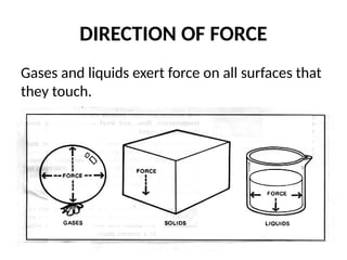
• The diagram below shows the direction of force exerted by solid, liquids, and
gases.
APPLIED FORCE
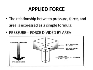
• Therelationship between pressure, force, and
area is expressed as a simple formula:
• PRESSURE = FORCE DIVIDED BY AREA
14.
ATMOSPHERIC PRESSURE
• Everythingon earth is exposed to atmospheric pressure.
• We know that air is a gas. We also know that a gas has weight.
• The atmosphere exerts a force of 14.7 pounds on all surfaces of an
object at sea level.
• The standard value of atmospheric pressure is 14.7 psi.
15.
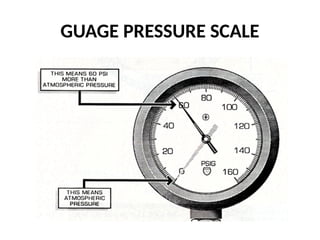
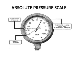
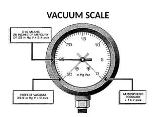
PRESSURE GAUGES ANDSCALES
• There are three common scales for measuring
pressure:
• Gauge Pressure Scale.
• Absolute Pressure Scale.
• Vacuum Scale.
• U TUBEMANOMETER
0
1
2
3
1
2
3
1
2
3
1
2
3
1
2
3
1
2
3
1
2
3
1
2
3
0 0
0
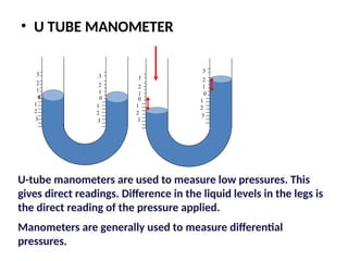
U-tube manometers are used to measure low pressures. This
gives direct readings. Difference in the liquid levels in the legs is
the direct reading of the pressure applied.
Manometers are generally used to measure differential
pressures.
21.
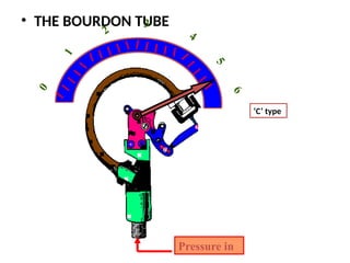
• THE BOURDONTUBE
‘C’ type
3
0
2 4
1
6
5
Pressure in
22.
¨ The Bourdontube is very common among pressure measuring
instruments.
¨ It works on Bourdon’s principle.
¨ “Any body deformed ( changed ) in it’s shape will try to regain
it’s original shape under the influence of temperature and
pressure”.
¨ A Bourdon tube consists of a hollow, curved metal tube closed
at one end. As pressure is applied to the open end the tube tries
to straighten itself out.
¨ The closed end ( tip ) has a mechanical linkage attached to a
gauge pointer or the indicator. As the pressure applied the tube
tries to straighten, creating a small movement at the tip. This
small movement is changed by the mechanical linkage to a larger
movement at the gauge pointer or recorder.
¨ There are several designs such as ‘C’ type, helical, spiral, etc.
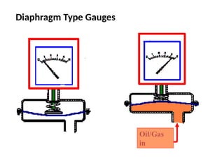
¨ Diaphragm typegauges can be used for both
low and high pressure measurements.
¨ Diaphragms are made up of rubber or thin
metal.
¨ Fluid enters inside the chamber and as the
pressure increases or decreases the
diaphragm moves back & forth and it is
linked mechanically to a pointer.
25.
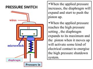
PRESSURE SWITCH
¨When theapplied pressure
increases, the diaphragm will
expand and start to push the
piston up.
¨When the applied pressure
reaches the high pressure
setting , the diaphragm
expands to its maximum and
the piston when it moves up
will activate some kind of
electrical contact to energise
the high pressure shutdown
system.
Pressure in
diaphragm
microswitch
wires
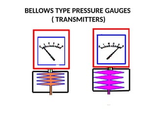
The Bellows elementis a cylindrical tube .
¨ Generally made up of thin metal or rubber
tube and it is pleated.
¨ Bellows can be used to measure both low and
high pressures.
¨ Bellows can be used to measure differential
pressures also.
¨ As the pressure is applied the bellows expands
and moves the linkage connected to it.
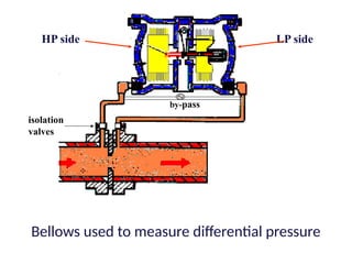
28.
Bellows used tomeasure differential pressure
HP side LP side
by-pass
isolation
valves
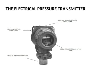
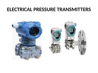
• Electrical transmittershave replaced pneumatic transmitters in
most petrochemical plants.
• This is because they are cheaper to install and maintain.
• The transmission of the signal is also cheaper and easier to install.
• This is because an electrical transmitter has one pair of wires
instead of expensive stainless steel signal tubing and air supply
lines.
• There arethree main types of transmitters.
• They mainly use two kinds of capsules: capacitive (Rosemount)
and strain gauge (Honeywell).
• The output from the capsule is electronically converted to a
STANDARD Smart 4-20 mA SIGNAL for transmission to the
control room.
• An electrical transmitter is calibrated with an instrument
screwdriver or push buttons.
• There are two adjustments, zero and span (range).
33.
• The calibrationand servicing depends on the
manufacturer.
• It must be carried out using the manual.
• Modern transmitters have become throw away items.
• If they cannot be calibrated they are not serviced.
• They are thrown away and replaced with a new
transmitter.
34.
PRINCIPLE OF LEVELMEASUREMENT
INTRODUCTION:
• LEVEL MEASUREMENT IS GAUGING THE POSITION OF THE TOP SURFACE
OF LIQUID or SOLID RELATIVE TO A FIXED REFERENCE or ZERO POINT.
• MEASUREMENT OF LIQUID LEVEL IS THE MEASUREMENT OF LIQUID
HEIGHT.
• UNITS OF LEVEL MEASUREMENTS:
• Level is actually the height, therefore unit of the length should be used.
• Unit of length in SI is metre (m).
• So the level can be given in millimetres, centimetres or metres.
35.
The Level Variable
Dipstick
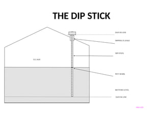
• The dip stick is a long calibrated ruler.
• The depth of the liquid in the tank is indicated by a WET mark
when the stick is removed.
• It's the same principle as checking the oil level of a car.
36.
• Because theremay be rubbish at the bottom of the tank the level may be taken from
a bottom level datum line.
• A datum line is a base line from which things can be measured.
• There is also a top datum line which is used to measure the space above the liquid
(the ullage).
• It is still used by operators and ships' captains to check that the instrumentation
which measures the level of a liquid in a tank is correct.
DIP TAPE
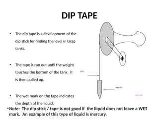
• Thedip tape is a development of the
dip stick for finding the level in large
tanks.
• The tape is run out until the weight
touches the bottom of the tank. It
is then pulled up.
• The wet mark on the tape indicates
the depth of the liquid.
•Note: The dip stick / tape is not good if the liquid does not leave a WET
mark. An example of this type of liquid is mercury.
TAPE
WEIGHT
IN01-030
39.
THE SIGHT GLASS
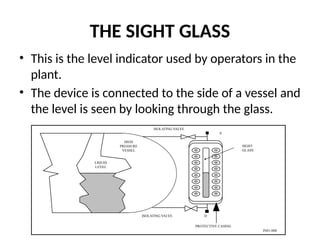
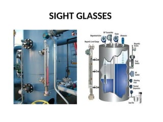
•This is the level indicator used by operators in the
plant.
• The device is connected to the side of a vessel and
the level is seen by looking through the glass.
LIQUID
LEVEL
HIGH
PRESSURE
VESSEL
PROTECTIVE CASING
A
D
ISOLATING VALVE
SIGHT
GLASS
ISOLATING VALVE
IN01-008
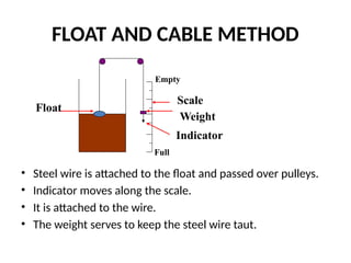
FLOAT AND CABLEMETHOD
• Steel wire is attached to the float and passed over pulleys.
• Indicator moves along the scale.
• It is attached to the wire.
• The weight serves to keep the steel wire taut.
Full
Empty
Float
Scale
Weight
Indicator