1
08A012 Automatic Transmission
DEPARTMENT ELECTIVE - DESIGN ENGINEERING
1. INTRODUCTION
2. CENTRIFUGAL CLUTCHES AND FLUID COUPLING
3. AUTOMATIC OVER DRIVES
4. HYDRODYNAMIC TORQUE CONVERTERS
5. HYDROSTATIC DRIVES
6. TYPICAL AUTOMATIC TRANSMISSION SYSTEMS
7. ELECTRIC DRIVES
08A012 Automatic Transmission
TEXT BOOKS:
1. Jack Erjavec, “Automatic Transmissions”, Delmar
Publishers,1st edition,2005.
2. Tom Birch and Chnck Rockmood, “Automatic Transmissions
and Transaxles”, Prentice Hall,1st edition,2002.
REFERENCES:
1. William Turney, “Automatic Transmissions and Transaxles”,
Chek Chart Publishers,1997.
2. Tucker H F, “Automatic Transmission”, Van Nostrand
Reinhold Company,1980.
3. Mathias F Brejeha, “Automatic Transmission”, Prentice
Hall,1998.
2
08A012 Automatic Transmission
INTRODUCTION:
•Principles of Automatic Transmission
•Advantages, Limitations
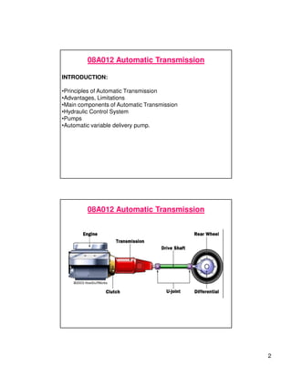
•Main components of Automatic Transmission
•Hydraulic Control System
•Pumps
•Automatic variable delivery pump.
08A012 Automatic Transmission
3
08A012 Automatic Transmission
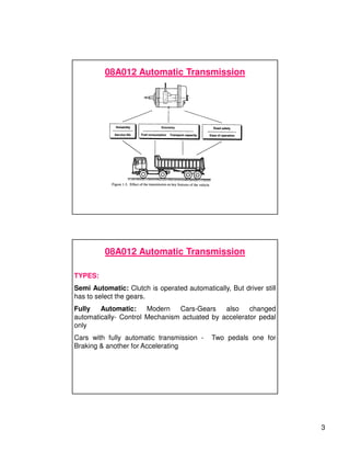
TYPES:
Semi Automatic: Clutch is operated automatically, But driver still
has to select the gears.
Fully Automatic: Modern Cars-Gears also changed
automatically- Control Mechanism actuated by accelerator pedal
only
Cars with fully automatic transmission - Two pedals one for
Braking & another for Accelerating
08A012 Automatic Transmission
4
08A012 Automatic Transmission
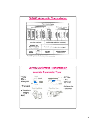
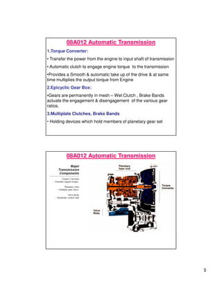
Automatic Transmission Types
•FWD –
More
Compact
•Transaxle
•Differential
– Integral
part
•RWD –
Less
Compact
•Differential
–External
5
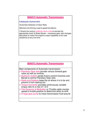
08A012 Automatic Transmission
1.Torque Converter:
• Transfer the power from the engine to input shaft of transmission
• Automatic clutch to engage engine torque to the transmission
•Provides a Smooth & automatic take up of the drive & at same
time multiplies the output torque from Engine
2.Epicyclic Gear Box:
•Gears are permanently in mesh – Wet Clutch , Brake Bands
actuate the engagement & disengagement of the various gear
ratios.
3.Multiplate Clutches, Brake Bands
• Holding devices which hold members of planetary gear set
08A012 Automatic Transmission
6
08A012 Automatic Transmission
4.Hydraulic Control Unit:
•Automatic Selection of Gear Ratio
•Monitors the Driving Load & speed Conditions
• Directs the various hydraulic servo units to actuate the
appropriate clutch & Brake Bands – necessary gear ratio changes
take place to match the engine’s output capability & the road
resistance at any one time.
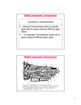
Main components of Automatic transmission:
 Planetary Gear sets provide various forward gear
ratios as well as reverse.
 Hydraulic system sends fluid to control Clutches and
Bands to control Planetary Gear sets.
 Seals and Gaskets keep the oil where it is to be and
prevent it from leaking out.
 Torque Converter provides continuously variable
torque ratio to a max of 1:2.5
 The Governor  Modulator or Throttle cable monitor
speed  throttle position to determine when to shift.
 A large gear pump to move transmission fluid around
08A012 Automatic Transmission
7
AUTOMATIC TRANSMISSION
 Manual Transmission locks  unlocks
gear sets to output shaft for different gear
ratios.
 In Automatic Transmission same set of
gears produce different gear ratios
08A012 Automatic Transmission
8
08A012 Automatic Transmission
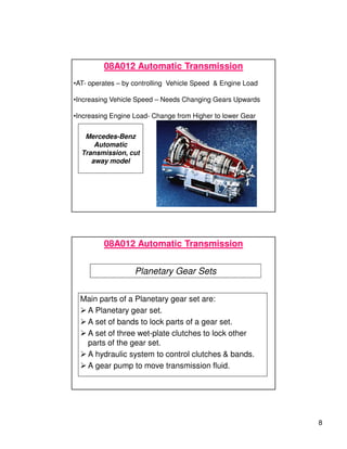
•AT- operates – by controlling Vehicle Speed  Engine Load
•Increasing Vehicle Speed – Needs Changing Gears Upwards
•Increasing Engine Load- Change from Higher to lower Gear
Mercedes-Benz
Automatic
Transmission, cut
away model
Planetary Gear Sets
Main parts of a Planetary gear set are:
 A Planetary gear set.
 A set of bands to lock parts of a gear set.
 A set of three wet-plate clutches to lock other
parts of the gear set.
 A hydraulic system to control clutches  bands.
 A gear pump to move transmission fluid.
08A012 Automatic Transmission
9
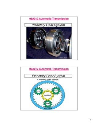
Planetary Gear System
08A012 Automatic Transmission
Planetary Gear System
08A012 Automatic Transmission
10
Planetary Gear System
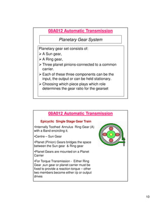
Planetary gear set consists of:
 A Sun gear,
 A Ring gear,
 Three planet pinions-connected to a common
carrier.
 Each of these three components can be the
input, the output or can be held stationary.
 Choosing which piece plays which role
determines the gear ratio for the gearset
08A012 Automatic Transmission
Epicyclic Single Stage Gear Train
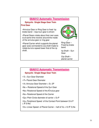
•Internally Toothed Annulus Ring Gear (A)
with a Band encircling it.
•Centre – Sun Gear
•Planet (Pinion) Gears bridges the space
between the Sun gear  Ring gear
•Planet Gears are mounted on a Planet
Carrier
•For Torque Transmission - Either Ring
Gear ,sun gear or planet carrier must be
fixed to provide a reaction torque – other
two members become either i/p or output
drives
08A012 Automatic Transmission
11
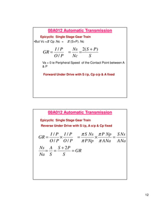
First Gear
Ring Gear –
Fixed by brake
band
I/p Shaft – Sun
Gear
O/p Shaft –
planet carrier
•Annulus Gear or Ring Gear is fixed by
brake band – input sun gear is driven
•Planet Gears rotate about their own axes
 at same time revolve around the inside
of the annulus gear or ring gear
•Planet Carrier which supports the planet
gear axes connected to o/p shaft made to
rotate but at a speed lower that of the i/p
shaft.
08A012 Automatic Transmission
Epicyclic Single Stage Gear Train
• S = Sun Gear Diameter
• P= Planet Gear Diameter
• A= Annulus Gear Diameter = S+ 2P
•Ns = Rotational Speed of the Sun Gear
•Na= Rotational Speed of the Annulus gear
•Nc= Rotational Speed of the Carrier
•Cp= Pitch Circle diameter of carrier = S+P
•Vs= Peripheral Speed of the Contact Point between S  P
( S.Ns)
•Vc= Linear Speed of Planet Carrier – half of Vs =1/2 S.Ns
π
π
π
08A012 Automatic Transmission
Epicyclic Single Stage Gear Train
12
•But Vc = Cp .Nc = (S+P). Nc
π π
S
P
S
Nc
Ns
P
O
P
I
GR
)
(
2
/
/ +
=
=
=
Forward Under Drive with S i/p, Cp o/p  A fixed
Va = 0 ie Peripheral Speed of the Contact Point between A
 P
08A012 Automatic Transmission
Epicyclic Single Stage Gear Train
Reverse Under Drive with S i/p, A o/p  Cp fixed
GR
S
P
S
S
A
Na
Ns
Na
A
Ns
S
Na
A
Np
P
Np
P
Ns
S
P
O
P
I
P
O
P
I
GR
=
+
=
=
=
×
=
×
=
2
/
/
/
/
π
π
π
π
08A012 Automatic Transmission
Epicyclic Single Stage Gear Train
13
08A012 Automatic Transmission
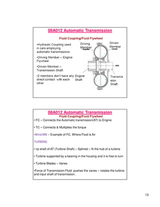
• FC – Connects the Automatic transmission(AT) to Engine
• TC – Connects  Multiplies the torque
•Wind Mill – Example of FC, Where Fluid is Air
TURBINE:
• i/p shaft of AT (Turbine Shaft) – Splined – fit the hub of a turbine
• Turbine supported by a bearing in the housing and it is free to turn
• Turbine Blades – Vanes
•Force of Transmission Fluid pushes the vanes – rotates the turbine
and input shaft of transmission.
14
08A012 Automatic Transmission
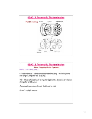
IMPELLER  HOUSING:
• Force the Fluid – Vanes are attached to housing - Housing turns
with Engine, Impeller act as pump.
•FC – Fluid is forced back to impeller against the direction of rotation
of impeller and Engine.
•Reduces the amount of work that is performed
•It can’t multiply torque.
15
08A012 Automatic Transmission
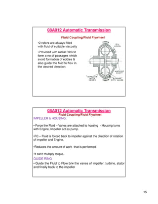
IMPELLER  HOUSING:
• Force the Fluid – Vanes are attached to housing - Housing turns
with Engine, Impeller act as pump.
•FC – Fluid is forced back to impeller against the direction of rotation
of impeller and Engine.
•Reduces the amount of work that is performed
•It can’t multiply torque.
GUIDE RING
• Guide the Fluid to Flow b/w the vanes of impeller ,turbine, stator
and finally back to the impeller
16
08A012 Automatic Transmission
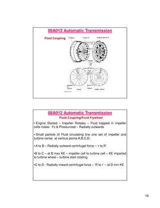
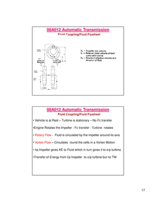
• Engine Started – Impeller Rotates – Fluid trapped in impeller
cells rotate- Fc  Pressurized – Radially outwards
• Small particle of Fluid circulating b/w one set of impeller and
turbine vanes at various points A,B,C,D.
• A to B – Radially outward centrifugal force – ‘r to R’
•B to C – at B max KE – impeller cell to turbine cell – KE imparted
to turbine wheel – turbine start rotating
•C to D - Radially inward centrifugal force – ‘R to r’ – at D min KE
17
08A012 Automatic Transmission
• Vehicle is at Rest – Turbine is stationary – No Fc transfer
•Engine Rotates the Impeller - Fc transfer - Turbine rotates
• Rotary Flow - Fluid is circulated by the impeller around its axis
• Vortex Flow – Circulates round the cells in a Vortex Motion
• I/p Impeller gives KE to Fluid which in turn gives it to o/p turbine
•Transfer of Energy from I/p Impeller to o/p turbine but no TM
18
08A012 Automatic Transmission
TORQUE CONVERTER
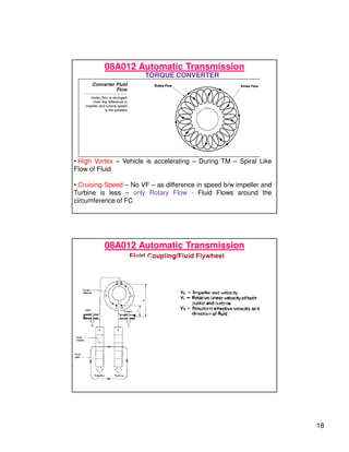
• High Vortex – Vehicle is accelerating – During TM – Spiral Like
Flow of Fluid
• Cruising Speed – No VF – as difference in speed b/w impeller and
Turbine is less – only Rotary Flow - Fluid Flows around the
circumference of FC
08A012 Automatic Transmission
19
08A012 Automatic Transmission
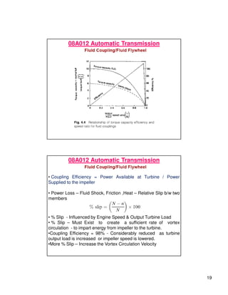
• Coupling Efficiency = Power Available at Turbine / Power
Supplied to the impeller
• Power Loss – Fluid Shock, Friction ,Heat – Relative Slip b/w two
members
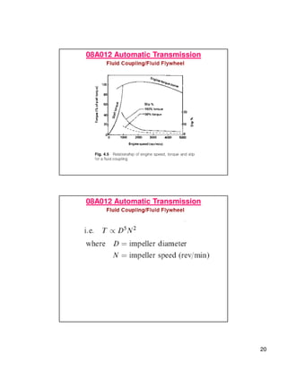
• % Slip - Influenced by Engine Speed  Output Turbine Load
• % Slip – Must Exist to create a sufficient rate of vortex
circulation - to impart energy from impeller to the turbine.
•Coupling Efficiency = 98% - Considerably reduced as turbine
output load is increased or impeller speed is lowered.
•More % Slip – Increase the Vortex Circulation Velocity
20
08A012 Automatic Transmission
21
08A012 Automatic Transmission
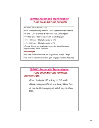
FLUID COUPLING/FLUID FLYWHEEL
08A012 Automatic Transmission
FLUID COUPLING/FLUID FLYWHEEL
22
08A012 Automatic Transmission
AUTOMATIC TRANSMISSION- WORKING FLUID
REQUIREMENTS/FUNCTIONS/PROPERTIES
• Transmits Engine Torque
• Controls Hydraulic System
• Applies Clutches and Brakes
• Lubricates Moving Parts
• Removes Heat From Internal Parts
• Seal the parts  Cleans
08A012 Automatic Transmission
AUTOMATIC TRANSMISSION- WORKING FLUID
•Natural or Synthetic oil because oil is capable of transmitting power, is a
lubricant, and is able to absorb and dissipate heat.
•Water as the fluid in fluid couplings, but sealing problems (keeping water
out of the bearings and oil out of the water) and corrosion occurs.
•Motor Oil –used as Transmission Fluid
•ATF – high grade petroleum product – Special Chemical Additives
• Transmission oil pump pressurize it – fed in to TC –Transmits the torque
generated by engine to transmission
• Pressurized ATF flows through the passages and valves to operate the
clutches and brakes
•Cools , Cleans and lubricates all moving parts
23
08A012 Automatic Transmission
AUTOMATIC TRANSMISSION- WORKING FLUID- TYPES
• Dexron , Dexron II – GM, Chrysler - Dyed Red
• Type F – Ford Motor Company – Dyed Red
• CJ Fluid – Amber Orange Color
• Fluids with appropriate coefficient of friction must be chosen
based on type of lining used for clutches, bands.
08A012 Automatic Transmission
AUTOMATIC TRANSMISSION- WORKING FLUID- TYPES
• Type T – Latest Type – All Transaxles
24
08A012 Automatic Transmission
AUTOMATIC TRANSMISSION- WORKING FLUID- ADDITIVES
Viscosity Index Improvers:
• Oil become thin at high temperatures and thick at low
temperatures.
• High Viscosity Index will stay at a more constant viscosity.
Pour Point Depressants:
Oil become too thick to pour at low temperatures- helps the oil to
flow at lower temperatures
Oxidation Inhibitors:
When clutch or Band applied – temp is as high as 600 F- oil
combines with O2 –oxidation – form gum and varnish
08A012 Automatic Transmission
AUTOMATIC TRANSMISSION- WORKING FLUID- ADDITIVES
Foam Inhibitors:
• Gear train of a transmission – air into fluid forming foam –
aeration – undesirable – air can be compressed – would keep the
clutches or bands from locking up – incorrect fluid level cause
aeration
Detergents - Depresants:
Corrosion and Rust Inhibitors:
•At high temp, water, oxygen and oil will form acids - form rust
and corrode parts. CI – neutralize the acids, RI – prevent water
from damaging the transmission parts
• Clean the Parts and valves , clean sludge ,varnish
25
08A012 Automatic Transmission
AUTOMATIC TRANSMISSION- WORKING FLUID- ADDITIVES
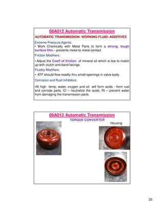
Extreme Pressure Agents:
• Work Chemically with Metal Parts to form a strong, tough
surface film – prevents metal to metal contact
Friction Modifiers:
Corrosion and Rust Inhibitors:
•At high temp, water, oxygen and oil will form acids - form rust
and corrode parts. CI – neutralize the acids, RI – prevent water
from damaging the transmission parts
• Adjust the Coeff of friction of mineral oil which is low to match
up with clutch and band facings.
Fluidity Modifiers:
• ATF should flow readily thru small openings in valve body.
08A012 Automatic Transmission
TORQUE CONVERTER
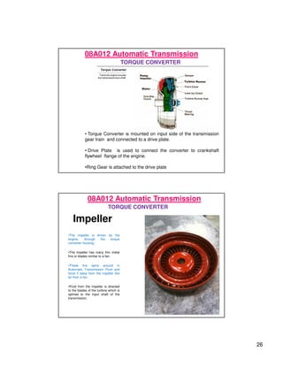
Housing
26
08A012 Automatic Transmission
TORQUE CONVERTER
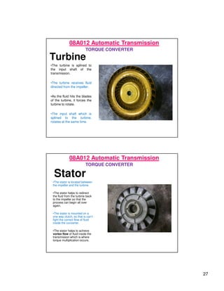
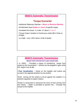
• Torque Converter is mounted on input side of the transmission
gear train and connected to a drive plate.
• Drive Plate is used to connect the converter to crankshaft
flywheel flange of the engine.
•Ring Gear is attached to the drive plate
Impeller
•The impeller is driven by the
engine, through the torque
converter housing.
•The impeller has many thin metal
fins or blades similar to a fan.
•These fins spins around in
Automatic Transmission Fluid and
force it away from the impeller like
air from a fan.
•Fluid from the impeller is directed
to the blades of the turbine which is
splined to the input shaft of the
transmission.
08A012 Automatic Transmission
TORQUE CONVERTER
27
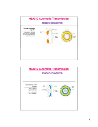
Turbine
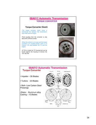
•The turbine is splined to
the input shaft of the
transmission.
•The turbine receives fluid
directed from the impeller.
•As the fluid hits the blades
of the turbine, it forces the
turbine to rotate.
•The input shaft which is
splined to the turbine,
rotates at the same time.
08A012 Automatic Transmission
TORQUE CONVERTER
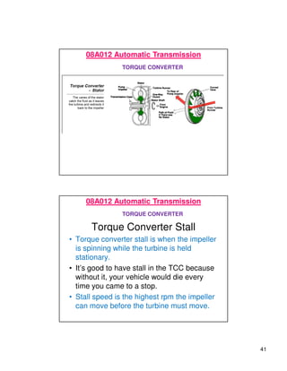
Stator
•The stator is located between
the impeller and the turbine.
•The stator helps to redirect
the fluid from the turbine back
to the impeller so that the
process can begin all over
again.
•The stator is mounted on a
one way clutch, so that is can’t
fight the correct flow of fluid
inside the converter.
•The stator helps to achieve
vortex flow of fluid inside the
transmission which is where
torque multiplication occurs.
08A012 Automatic Transmission
TORQUE CONVERTER
28
Torque Converter Clutch
•The torque converter clutch forms a
mechanical link between the transmission
input shaft and the engine.
•Fluid coupling from the converter is only
about 90% efficient at best.
•When the vehicle is at cruise and the torque
converter is in coupling phase, there is an
inherent 10% slip between the TC and the
engine.
•A TCC is inside the TC housing and can be
forced against the housing to remove the
10% slip rate.
08A012 Automatic Transmission
TORQUE CONVERTER
08A012 Automatic Transmission
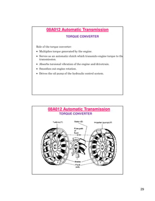
• Impeller – 26 Blades
• Turbine - 23 Blades
• Both- Low Carbon Steel
Pressings
•Stator - Aluminum alloy
Casting – 15 Blades
29
08A012 Automatic Transmission
TORQUE CONVERTER
08A012 Automatic Transmission
TORQUE CONVERTER
30
08A012 Automatic Transmission
TORQUE CONVERTER
08A012 Automatic Transmission
TORQUE
CONVERTER
31
08A012 Automatic Transmission
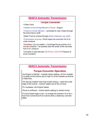
NEED FOR STATOR IN FLUID COUPLING
• In 1930’s - Provided a means of transferring torque from
engine to the transmission – Vehicle can be stopped in gear while
the engine runs at idle.
• Poor Acceleration – Vanes on the impeller and turbine are
curved in the opposite direction to one another
•Fluid coming off the turbine is thrust against the impeller in a
direction opposite to engine rotation.
•Power is consumed to overcome the force of fluid coming from
the turbine. – Stator is provided to prevent this – Increase the
torque to the impeller.
32
08A012 Automatic Transmission
33
08A012 Automatic Transmission
TORQUE CONVERTER
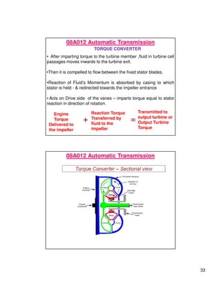
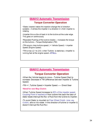
• After imparting torque to the turbine member ,fluid in turbine cell
passages moves inwards to the turbine exit.
•Then it is compelled to flow between the fixed stator blades.
•Reaction of Fluid’s Momentum is absorbed by casing to which
stator is held -  redirected towards the impeller entrance
• Acts on Drive side of the vanes – imparts torque equal to stator
reaction in direction of rotation.
Engine
Torque
Delivered to
the impeller
+
Reaction Torque
Transferred by
fluid to the
impeller
=
Transmitted to
output turbine or
Output Turbine
Torque
08A012 Automatic Transmission
34
08A012 Automatic Transmission
35
08A012 Automatic Transmission
TORQUE CONVERTER
08A012 Automatic Transmission
TORQUE CONVERTER
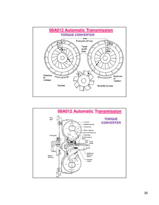
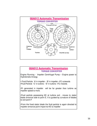
Engine Running - Impeller Centrifugal Pump – Engine power to
Hydrokinetic Energy
• Fluid Particle ‘A’ in impeller - ‘B’ in impeller –FC outwards
•Fluid Particle ‘C’ in turbine - ‘D’ in turbine –FC inwards
•Pr generated in impeller will be far greater than turbine as
impeller speed is more.
•Fluid particle possessing KE at turbine exit , moves to stator
blade entrance side to point E. It is guided by curvature of blades
to exit point F
•From the fixed stator blade the fluid particle is again directed to
impeller entrance point impart its KE to impeller
36
08A012 Automatic Transmission
TORQUE CONVERTER
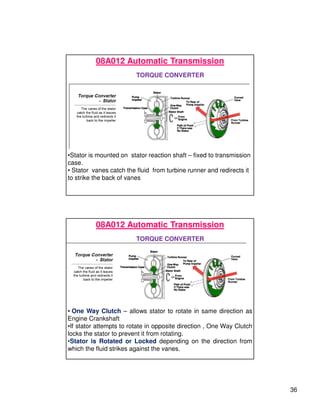
•Stator is mounted on stator reaction shaft – fixed to transmission
case.
• Stator vanes catch the fluid from turbine runner and redirects it
to strike the back of vanes
08A012 Automatic Transmission
TORQUE CONVERTER
• One Way Clutch – allows stator to rotate in same direction as
Engine Crankshaft
•If stator attempts to rotate in opposite direction , One Way Clutch
locks the stator to prevent it from rotating.
•Stator is Rotated or Locked depending on the direction from
which the fluid strikes against the vanes.
37
08A012 Automatic Transmission
TORQUE CONVERTER
08A012 Automatic Transmission
TORQUE CONVERTER
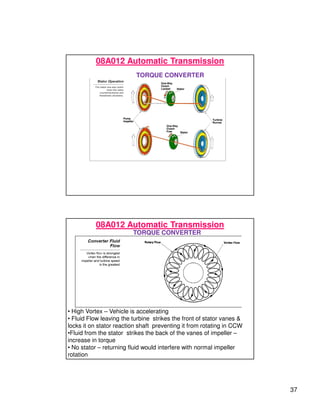
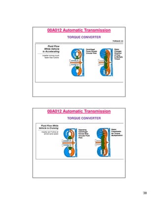
• High Vortex – Vehicle is accelerating
• Fluid Flow leaving the turbine strikes the front of stator vanes 
locks it on stator reaction shaft preventing it from rotating in CCW
•Fluid from the stator strikes the back of the vanes of impeller –
increase in torque
• No stator – returning fluid would interfere with normal impeller
rotation
38
08A012 Automatic Transmission
TORQUE CONVERTER
08A012 Automatic Transmission
TORQUE CONVERTER
39
08A012 Automatic Transmission
40
08A012 Automatic Transmission
TORQUE CONVERTER
08A012 Automatic Transmission
TORQUE CONVERTER
41
08A012 Automatic Transmission
TORQUE CONVERTER
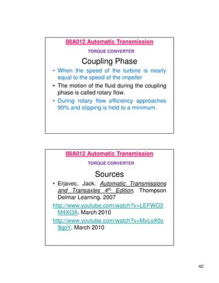
Torque Converter Stall
• Torque converter stall is when the impeller
is spinning while the turbine is held
stationary.
• It’s good to have stall in the TCC because
without it, your vehicle would die every
time you came to a stop.
• Stall speed is the highest rpm the impeller
can move before the turbine must move.
08A012 Automatic Transmission
TORQUE CONVERTER
42
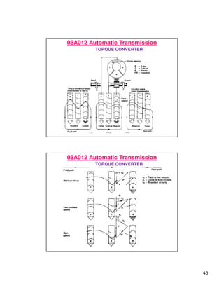
Coupling Phase
• When the speed of the turbine is nearly
equal to the speed of the impeller
• The motion of the fluid during the coupling
phase is called rotary flow.
• During rotary flow efficiency approaches
90% and slipping is held to a minimum.
08A012 Automatic Transmission
TORQUE CONVERTER
Sources
• Erjavec, Jack. Automatic Transmissions
and Transaxles 4th Edition. Thompson
Delmar Learning. 2007
http://www.youtube.com/watch?v=LEFWO3
M4XOA. March 2010
http://www.youtube.com/watch?v=MvLoX0z
9qoY. March 2010
08A012 Automatic Transmission
TORQUE CONVERTER
43
08A012 Automatic Transmission
TORQUE CONVERTER
08A012 Automatic Transmission
TORQUE CONVERTER
44
08A012 Automatic Transmission
TORQUE CONVERTER
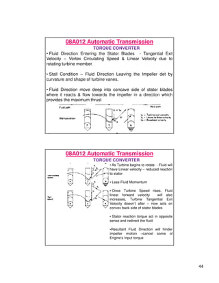
• Fluid Direction Entering the Stator Blades - Tangential Exit
Velocity – Vortex Circulating Speed  Linear Velocity due to
rotating turbine member
• Stall Condition – Fluid Direction Leaving the Impeller det by
curvature and shape of turbine vanes.
• Fluid Direction move deep into concave side of stator blades
where it reacts  flow towards the impeller in a direction which
provides the maximum thrust
08A012 Automatic Transmission
TORQUE CONVERTER
• As Turbine begins to rotate - Fluid will
have Linear velocity – reduced reaction
to stator
• Less Fluid Momentum
• Once Turbine Speed rises, Fluid
linear forward velocity will also
increases, Turbine Tangential Exit
Velocity doesn’t alter – now acts on
convex back side of stator blades
• Stator reaction torque act in opposite
sense and redirect the fluid.
•Resultant Fluid Direction will hinder
impeller motion –cancel some of
Engine’s Input torque
45
08A012 Automatic Transmission
TORQUE CONVERTER
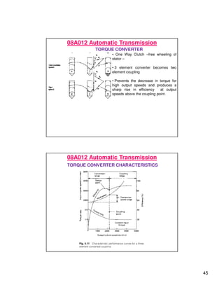
• One Way Clutch –free wheeling of
stator –
• 3 element converter becomes two
element coupling
• Prevents the decrease in torque for
high output speeds and produces a
sharp rise in efficiency at output
speeds above the coupling point.
08A012 Automatic Transmission
TORQUE CONVERTER CHARACTERISTICS
46
08A012 Automatic Transmission
TORQUE CONVERTER CHARACTERISTICS
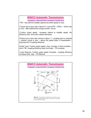
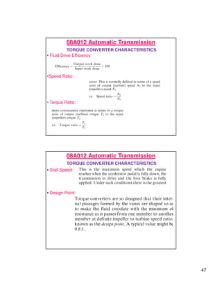
• TM – max (diff b/w impeller speed and turbine speed is max)
• Torque o/p to input ratio of about 2:1 occurs(TR) – STALL – Vortex rate
is max – Max Hydrokinetic energy transfer occurs
• Turbine output speed increases relative to impeller speed, the
efficiency rises and vortex velocity decrease
•Torque o/p to input ratio comes to about 1:1, coupling point is reached
– reaction torque is zero – above this speed stator is freewheeled –
Improvement in coupling efficiency
•Under Load, Turbine output speed drop, increase in fluid circulation ,
rise in TM , coupling efficiency drop (more slip) – TR increases
• Load Reduces, Turbine output speed increases , coupling efficiency
increases (less slip) – TR Reduces
08A012 Automatic Transmission
TORQUE CONVERTER CHARACTERISTICS
47
08A012 Automatic Transmission
TORQUE CONVERTER CHARACTERISTICS
• Fluid Drive Efficiency:
•Speed Ratio:
• Torque Ratio:
08A012 Automatic Transmission
TORQUE CONVERTER CHARACTERISTICS
• Stall Speed:
• Design Point:
48
08A012 Automatic Transmission
TORQUE CONVERTER CHARACTERISTICS
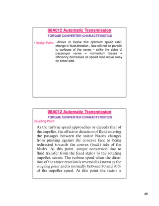
• Design Point: • Above or Below this optimum speed ratio,
change in fluid direction , flow will not be parallel
to surfaces of the vanes – strike the sides of
passenger vanes – momentum losses –
efficiency decreases as speed ratio move away
on either side.
08A012 Automatic Transmission
TORQUE CONVERTER CHARACTERISTICS
Coupling Point:
49
08A012 Automatic Transmission
TORQUE CONVERTER CHARACTERISTICS
Racing or Run- Away Point:
• Stator Not Functioning – fluid direction against impeller rotation –
Vortex flow declines – Torque capacity of the converter
approaches zero – Turbine speed catches up with that of impeller
• Accelerator Pedal fully down – very little load – impeller and
turbine rotate at same speed, vortex circulation ceases(fluid
resistance)