Advanced Prosthetic Knee
Joint
KARTHIK M ANIL
MPO 1ST BATCH
INTRODUCTION
• It is the mechanical knee joint replica for anatomic knee functioning for
any above knee prosthesis .
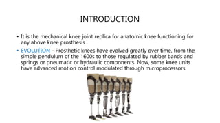
• EVOLUTION - Prosthetic knees have evolved greatly over time, from the
simple pendulum of the 1600s to those regulated by rubber bands and
springs or pneumatic or hydraulic components. Now, some knee units
have advanced motion control modulated through microprocessors.
CLASSIFICATION
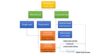
• The plethora of presently available prosthetic knee components
can be divided into two groups based on how they are
controlled:
• Recent innovations that incorporate an onboard computer and
the more familiar purely mechanical devices.
• These categories then can be subdivided into generic functional
classes based on the degree of stance phase stability and swing
phase responsiveness offered by each type of knee mechanism
Prosthetic
knee joint
Mechanical
Single axis Polycentric
STABILIZING
MECHANISM
Manual Locking /
Weight-Activated
MOTION
CONTROL
Constant Friction Vs
Variable Friction
Computerized
Hybrid knee
mechanisms
Microchip
controlled
Hydraulic
Pneumatic
STANCE PHASE CONTROL
SWING PHASE CONTROL
SWING PHASE CONTROL
Single-axis knee Joint
• The single-axis knee, essentially a simple hinge, is
generally considered the “workhorse” of the basic knee
classes due to its relative simplicity, which makes it the
most economical, most durable, and lightest option
available.
• LIMITATION - By virtue of their simplicity, the knees are
free-swinging and have no stance control; amputees
must use their own muscle power to keep them stable
when standing.
• To compensate for this, the single-axis knee often
incorporates a constant friction control and a manual
lock. The friction keeps the leg from swinging forward too
quickly as it swings through to the next step.
Polycentric knee joint
• The polycentric knee has two or more pairs of bars
connecting the upper and lower portions of the unit.
The bars pivot at both ends thus creating a moving
center of rotation.
• As the wearer bends the knee, the bars cross
proximally and posteriorly, thereby changing the
center or rotation and thus promoting knee stability
during stance phase
• Because four linkage bars connect the four axes, the
polycentric knee also is referred to as a four-bar
design.
Instantaneous Centre of Rotation (ICoR)
• In most polycentric knee designs, the position of the ICOR
moves anteriorly and distally as the knee flexes, following a
curved pathway called the centrode. After the knee has been
flexed a few degrees, the ICOR now falls in front of the GRFV,
and the knee flexes automatically.
• polycentric knee can provide inherent stability in early stance
while still flexing easily in late stance during the preswing. Many
users prefer this combination of inherent stability plus ease of
voluntary swing phase initiation.
Various polycentric Knee Mechanisms
• As the knee flexes, the apparent or instantaneous centre of
rotation between the thigh and shank changes in a manner
which improves the stability characteristics of the knee and also
allows an increased range of knee flexion.
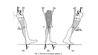
• Characteristics of stability (1) the instant centre of thigh-shank
rotation, (2) the load line, (3) the brake moment or torque
generated by the prosthetic knee, and (4) the hip moment which
can be supplied voluntarily by the amputee.
The position of the load line at heel contact or at toe off may be
related to the load P carried through the hip joint and the hip
moment exerted by the amputee. An extension moment moves
the load line ahead of the hip, a flexion moment moves it behind.
HYDRAULIC KNEE UNITS
• Swing control
• Hydraulic knee units regulate the
swing of the shank according to the
walker’s speed.
• The unit has an oil-filled cylinder
attached to the knee axis. A piston
from the axis to the cylinder interior
descends during early swing; this
action forces oil to flow through
narrow channels to provide frictional
resistance.
MICROPROCESSOR CONTROLLED
PROSTHETIC KNEES
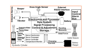
• Microprocessor knee units have electronic
sensors that monitor the action of hydraulic
knee units during swing and ground force
during stance. Sensors measure angles,
moments of force, and pressures at 50 or
more times per second.
• Adjustments can be made with a laptop or
handheld computer. Software algorithms
determine the phase of gait, automatically
adjusting knee functions to approximate
normal function.
MICROPROCESSOR CONTROLLED PROSTHETIC
KNEES
• First proposed concept by Kobe Steel researchers 2 decades ago, the
clinical application of microprocessors controls to prosthetic knee
mechanisms is a recent development.
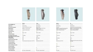
• 4 different microprocessor controlled knee prostheses using the sensor
technology and the units generating internal resistances are available:
1. C-Leg
2. Adaptive 2
3. SynergyKnie
4. RheoKnee
C-Leg
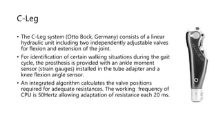
• The C-Leg system (Otto Bock, Germany) consists of a linear
hydraulic unit including two independently adjustable valves
for flexion and extension of the joint.
• For identification of certain walking situations during the gait
cycle, the prosthesis is provided with an ankle moment
sensor (strain gauges) installed in the tube adapter and a
knee flexion angle sensor.
• An integrated algorithm calculates the valve positions
required for adequate resistances. The working frequency of
CPU is 50Hertz allowing adaptation of resistance each 20 ms.
The Adaptive2
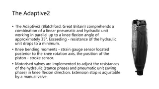
• The Adaptive2 (Blatchford, Great Britain) comprehends a
combination of a linear pneumatic and hydraulic unit
working in parallel up to a knee flexion angle of
approximately 35°. Exceeding - resistance of the hydraulic
unit drops to a minimum.
• Knee bending moments - strain gauge sensor located
posterior to the knee rotation axis, the position of the
piston - stroke sensor.
• Motorised valves are implemented to adjust the resistances
of the hydraulic (stance phase) and pneumatic unit (swing
phase) in knee flexion direction. Extension stop is adjustable
by a manual valve
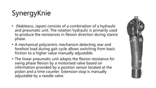
SynergyKnie
• (Nabtesco, Japan) consists of a combination of a hydraulic
and pneumatic unit. The rotation hydraulic is primarily used
to produce the resistances in flexion direction during stance
phase.
• A mechanical polycentric mechanism detecting rear and
forefoot load during gait cycle allows switching from basic
friction to a higher value manually adjustable.
• The linear pneumatic unit adapts the flexion resistance for
swing phase flexion by a motorised valve based on
information provided by a position sensor located at the
piston and a time counter. Extension stop is manually
adjustable by a needle valve
RheoKnee
• RheoKnee (Össur, Island)
• A rotation hydraulic unit according to a
magnetorheological concept is realised here.
• Resistance in both flexion and extension direction is
produced by changing the magnetic field and resulting
change of fluid viscosity.
• Force and moment sensors (strain gauges) installed
distally to the joint chassis and a knee flexion angle
sensor provide information with a frequency of 1000
Hertz. An adaptive control algorithm regulates the rate
of resistances.
Prescription Criteria
• The prescription of prosthetic components is not yet completely scientific,
although the amount of data obtained increases with each new published
study. But it now is possible to rule out specific components as being
unlikely to benefit a patient with an amputated limb based on a
biomechanical analysis of that person's goals and capabilities.
• Rehabilitation team discussion then can be limited to those plausible
alternatives components most likely to be clinically useful to the specific
user.
Q,s for Prescription
• The clinic team can determine each individual's stance and
swing control needs by answering four questions.
• Can this person be expected to use their remaining
neuromuscular capacity to:(1) control prosthetic knee stability
under all circumstances; (2) flex the prosthetic knee in a
controlled manner during preswing; (3) walk with a prosthesis at
differing speeds; and (4) walk with a prosthesis at a moderate or
faster pace?
• Single axis designs - Those patients who can control voluntarily the
stability of the prosthesis under all conditions may use one of the basic
single axis designs. The remaining majority should be offered one of the
more stable knee mechanisms according to their functional needs.
• Manual locking knee - few patients who are totally unable to control the
knee, perhaps because of a CVA affecting the amputated limb, may require
a manual locking knee. Whenever possible, however, patients should be
offered the opportunity to master a prosthetic knee that will bend during
swing phase.
• Constant Friction - recent amputation and feeble patients whose overall
physical condition will restrict them to very slow walking speeds may find a
friction brake stance control mechanical knee sufficient. But slow preswing
activation - not recommended for more active users.
• Polycentric joint - offer excellent inherent stability in combinations with
ease of knee flexion for swing phase clearance, making Polycentric knees
the preferred choice for most patients needing some degree of stance
stability who are otherwise in reasonably good health.
• long residual limb usually will prefer the special class of four-bar knee
prostheses designed to improve sitting cosmesis.
• Swing phase control - If the patient with an amputated limb is expected to
vary their walking speed, then mechanical swing control devices will be
insufficient and fluid control should be considered.
• The smaller and lighter hydraulic units and pneumatic cylinders usually are
sufficient for slow to moderate cadence walking, and often are prescribed
for smaller stature individuals, including women and children. Larger, more
powerful hydraulic swing phase controls are particularly appropriate for
the taller individual, the more active ambulator, and for those who
participate in competitive sports events.
• Microprocessor/Hybrid Knee - Specific indications for presently available
microprocessor controlled knee prostheses have not yet been established.
Because their long term durability is not yet fully documented, the ability
of the user to return for follow-up adjustments or servicing is certainly an
important consideration at this time.
• In general, it seems that those amputees who would be reasonably good
ambulators with conventional technology will derive the greatest benefits
from such sophisticated knee controls
REFERENCE
1. Michael, John W. MEd, CPO Modern Prosthetic Knee Mechanisms,
Clinical Orthopaedics and Related Research: April 1999 - Volume 361 -
Issue - p 39-47
2. Comparative Biomechanical Analysis of Current Microprocessor
Controlled Prosthetic Knee JointsM. Bellmann1, T. Schmalz, S.
BlumentrittOtto Bock HealthCare GmbH, Department of
Research/Biomechanics, Duderstadt, Germany
3. THE KNUD JANSEN LECTURE, Above-knee prosthetics, C. W. RADCLIFFE,
Prosthetics and Orthotics International, 1977, I, 146-160