CONTENTS
1. INTRODUCTION
2. ADVANTAGES
3.LIMITATIONS
4. CLASSIFICATION OF MICROPARTICLE
5. TYPE OF CORE MATERIALS, COATING MATERIALS
6. APPLICATIONS
7. TECHNIQUES TO MANUFACTURE
8. EVALUATION STUDIES
2.
Microencapsulation isa process by which solids, liquids or even
gases may be enclosed as microscopic particles by formation of thin
coatings of wall material around the substances.
or
Microencapsulation may be defined as the packaging technology of
solids, liquid or gaseous material with thin polymeric coatings,
forming small particles called microcapsules.
The polymer acts as a protective film, isolating the core and avoiding
any effect of its inadequate exposure. This membrane dissolves itself
through a specific stimulus, releasing the core in the ideal place or at
the ideal time.
The product obtained by this process is called as Microcapsules,
microsphere, coated granules, pellets.
Particle size: 0.2-5000 micron.
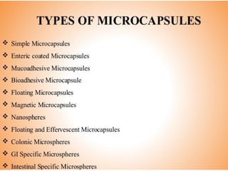
INTRODUCTION
2
Microcapsule
with liquid cores
Microcapsule
with Solid cores
3.
Difference Between Microcapsules& Microspheres
MICROCAPSULES
These are particles consisting of an inner core, substantially central,
containing the active substance, which is covered with a polymer layer
constituting the capsule membrane.
Mononuclear & polynuclear microcapsule can be distinguished by
whether the core is divided.
•MICROSPHERES
These are matrix systems in which the core is uniformly dispersed
and/or dissolved in a
polymer network.
Microspheres may be homogeneous or heterogeneous depending on
whether the core is in the molecular state (dissolved) or in the form
of particles (suspended), respectively.
1 μm to 1000 μm
4.
ADVANTAGES:
To Increase ofbioavailability
To alter the drug release (Sustained &prolonged release dosage form can
be formulated)
To improve the patient’s compliance
To produce a targeted drug delivery
To decrease evaporation rate of the core material.
To mask the core taste.
To reduce toxicity and GI irritation
Liquids& gases can be transformed to solids in the form of microcapsules.
Environmental protection is achieved.
Colloidal & surface properties of some core materials can be changed.
5.
• LIMITATIONS:
Manufacturingtech’s are costly.
shelf life of hygroscopic drugs is reduced.
Particles are not coated uniformly hence, release pattern
of
the drugs in the body is changed.
6.
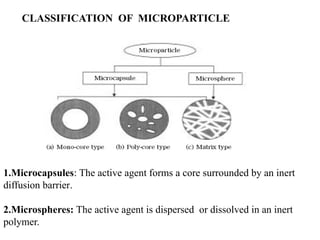
CLASSIFICATION OF MICROPARTICLE
1.Microcapsules:The active agent forms a core surrounded by an inert
diffusion barrier.
2.Microspheres: The active agent is dispersed or dissolved in an inert
polymer.
7.
7
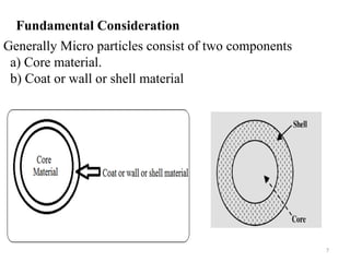
Generally Micro particlesconsist of two components
a) Core material.
b) Coat or wall or shell material
Fundamental Consideration
8.
8
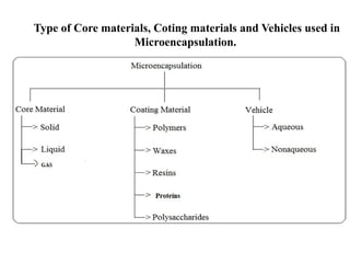
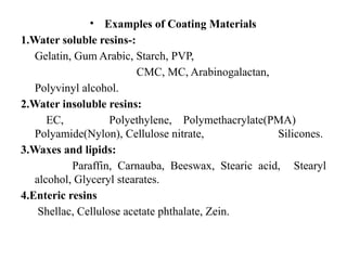
Type of Corematerials, Coting materials and Vehicles used in
Microencapsulation.
9.
CORE MATERIAL(C.M)
Thematerial to be coated may be liquid or solid or gas which is to be
enclosed in specific coating material.
Liquid core may be dissolved or dispersed material.
The solid core can be single solid substance or mixture of active
constituents,
Various C.M provide flexibility in obtaining required characters of
microsperes.
Composition of core material:
Drug or active constituent
Additives like
Diluents
Stabilizers
Diluents,
Excipients
Release-rate retardants or accelerators
10.
10
Coating Material
Inertsubstance which coats on core with desired thickness.
The selection of coating material decides the physical & chemical
properties of the resultant microcapsules/microspheres depends on
Necessities of dosage form like
Stability,
volatility,
Release characteristics,
Environmental conditions, etc.
Various colors & plasticizers are used along with coating material to
enhance the elegance of microsperes.
Composition of coating material:
Inert polymer
Plasticizer
Coloring agent
Resins, waxes and lipids
Release rate enhancers or retardants.
IDEAL PROPERTIES OFPOLYMERS:
The polymer should be capable of forming a film that is cohesive
with the core material.
It should be chemically compatible, non-reactive with the core
material.
It should provide the desired coating properties such as: Strength,
flexibility, impermeability, optical properties &stability.
Generally hydrophilic / hydrophobic polymers /a combination
of both are used for the microencapsulation process.
A number of coating materials have been used successfully
examples :Gelatin , polyvinyl alcohol, ethyl cellulose & CAP etc.
The film thickness can be varied considerably depending On the
surface area of the material to be coated & Other physical
characteristics of the system.
The microcapsules may consist of a single particle or clusters of
particles. 12
14
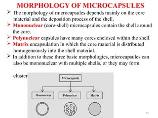
MORPHOLOGY OF MICROCAPSULES
The morphology of microcapsules depends mainly on the core
material and the deposition process of the shell.
Mononuclear (core-shell) microcapsules contain the shell around
the core.
Polynuclear capsules have many cores enclosed within the shell.
Matrix encapsulation in which the core material is distributed
homogeneously into the shell material.
In addition to these three basic morphologies, microcapsules can
also be mononuclear with multiple shells, or they may form
clusters of microcapsules.
15.
APPLICATIONS
Potential applicationsof this drug delivery system are replacement
of therapeutic agents (not taken orally today like insulin), gene
therapy and in use of vaccines for treating AIDS, tumors, cancer
and diabetes.
The delivery of corrective gene sequences in the form of plasmid
DNA could provide convenient therapy for a number of genetic
diseases such as cystic fibrosis and hemophilia.
To improve the flow properties. e.g. Thiamine, Riboflavin
To enhance the stability. e.g. Vitamins
To reduce the volatility of materials. e.g. Peppermint oil, Methyl
salicylate
To convert liquids into solids. e.g. Castor oil, Eprazinone,
To reduce gastric irritation. e.g. Nitrofurantoin, Indomethacin
16.
APPLICATIONS continued
Forformulation of Prolonged release dosage forms.
Prepare enteric-coated dosage forms selectively absorbed in the intestine
rather than the stomach.
It can be used to mask the taste of bitter & bad odour drugs.
To reduce gastric irritation.
For stabilization of core material.(microencapsulation of vitamins &
volatile oils.)
For formulation of parenteral preparation which are to be released @
specific sites.
For encapsulation of proteins & can be used to decrease the volatility.
The hygroscopic properties of many core materials may be reduced by
microencapsulation.
In the fabrication of multilayered tablet formulations for controlled
release of medicament contained in medial layers of tableted particles
Microencapsulation has also been used to decrease potential danger of
handling of toxic or noxious substances. Such as fumigants, herbicides,
insecticides and pesticides.
18
Techniques to ManufactureMicrocapsules
The technique of microencapsulation depends on the physical
and chemical properties of the material to be encapsulated.
The stability and the biological activity of the drug should not be
affected, Yield and drug encapsulation efficiency should be
high.
Microsphere quality and drug release profile should be
reproducible within specified limits.
Microsphere should not exhibit aggregation or adherence.
Process should be usable at an industrial scale.
19.
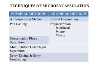
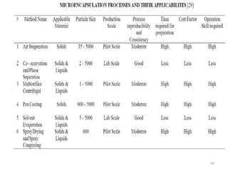
TECHNIQUES OF MICROENCAPSULATION
PHYSICALMETHODS CHEMICAL METHODS
Air Suspension Method Solvent Evaporation
Pan Coating Polymerization
Interfacial
In-situ
Matrix
Coacervation Phase
Separation
Multi -Orifice Centrifugal
Separation
Spray Drying & Spray
Congealing
20.
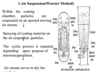
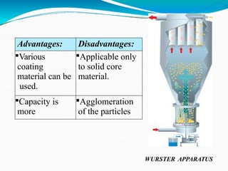
1.Air Suspension(Wurster Method)
Withinthe coating
chamber, particles are
suspended on an upward moving
air stream.
Spraying of coating material on
the air suspended particles.
The cyclic process is repeated
depending upon purpose of
microencapsulation.
Air stream serves to dry the WURSTER APPARATUS
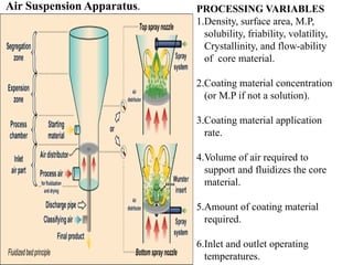
PROCESSING VARIABLES
1.Density, surfacearea, M.P,
solubility, friability, volatility,
Crystallinity, and flow-ability
of core material.
2.Coating material concentration
(or M.P if not a solution).
3.Coating material application
rate.
4.Volume of air required to
support and fluidizes the core
material.
5.Amount of coating material
required.
6.Inlet and outlet operating
temperatures.
Air Suspension Apparatus.
23.
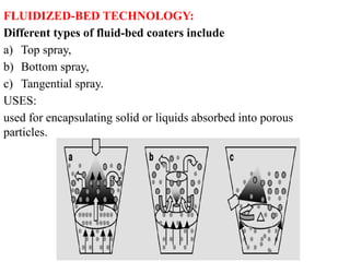
FLUIDIZED-BED TECHNOLOGY:
Different typesof fluid-bed coaters include
a) Top spray,
b) Bottom spray,
c) Tangential spray.
USES:
used for encapsulating solid or liquids absorbed into porous
particles.
24.
24
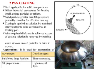
Tech applicable forsolid core particles.
Oldest industrial procedures for forming
small, coated particles or tablets.
Solid particle greater than 600µ size are
generally consider for effective coating.
Coating is applied as solution by atomized
spray to desired solid core material in
Coating pan.
After required thickness is achieved excess
of coating solution is removed by passing
warm air over coated particles or dried in
woven.
Applications: It is used for preparation of
controlled- release beads.
2 PAN COATING
Advantages: Disadvantages:
Suitable to large Particles. Time consuming.
SR preparations. High material
loss.
25.
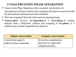
3 COACERVATION PHASESEPARATION
Coacervation Phase Separation refers to partial desolvation of a
homogeneous polymer solution into a polymer-rich phase (coacervate) and
the poor polymer phase(coacervation medium).
The term originated from the Latin (acervus meaning heap)
Coacervation involves the separation of a liquid phase of coating
material from a Polymeric solution and wrapping of that phase as a
uniform layer around suspended core particles.
Simple coacervation Complex coacervation
A desolvation agent is
added for phase separation
It involves complexation
between two oppositely
charged polymers.
26.
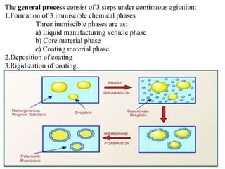
The general processconsist of 3 steps under continuous agitation:
1.Formation of 3 immiscible chemical phases
Three immiscible phases are as:
a) Liquid manufacturing vehicle phase
b) Core material phase
c) Coating material phase.
2.Deposition of coating
3.Rigidization of coating.
27.
27
27
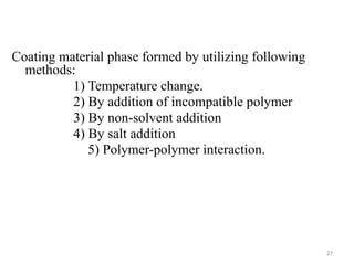
Coating material phaseformed by utilizing following
methods:
1) Temperature change.
2) By addition of incompatible polymer
3) By non-solvent addition
4) By salt addition
5) Polymer-polymer interaction.
28.
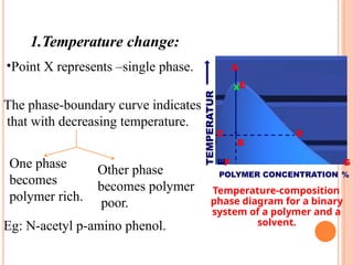
Temperature-composition
phase diagram fora binary
system of a polymer and a
solvent.
TEMPERATUR
E
B
C D
A
XE
F G
POLYMER CONCENTRATION %
1.Temperature change:
•Point X represents –single phase.
The phase-boundary curve indicates
that with decreasing temperature.
One phase
becomes
polymer rich.
Other phase
becomes polymer
poor.
Eg: N-acetyl p-amino phenol.
29.
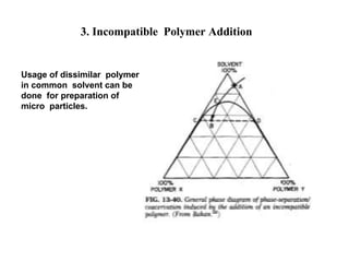
3. Incompatible PolymerAddition
Usage of dissimilar polymer
in common solvent can be
done for preparation of
micro particles.
10
30.
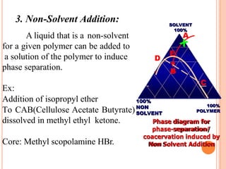
3. Non-Solvent Addition:
Aliquid that is a non-solvent
for a given polymer can be added to
a solution of the polymer to induce
phase separation.
Ex:
Addition of isopropyl ether
To CAB(Cellulose Acetate Butyrate)
dissolved in methyl ethyl ketone.
Core: Methyl scopolamine HBr.
A
B
C
D
E
SOLVENT
100%
100%
POLYMER
100%
NON
SOLVENT
Phase diagram for
phase-separation/
coacervation induced by
Non Solvent Addition
31.
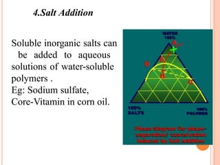
4.Salt Addition
Soluble inorganicsalts can
be added to aqueous
solutions of water-soluble
polymers .
Eg: Sodium sulfate,
Core-Vitamin in corn oil.
32.
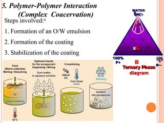
5. Polymer-Polymer Interaction
(ComplexCoacervation)
Steps involved:4
1. Formation of an O/W emulsion
2. Formation of the coating
3. Stabilization of the coating
WATE
R
1
00%
A
1%
0
0
100%
P+
Ternary Phase P -
diagram
XC
B
33.
4.MULTI ORIFICE CENTRIFUGATION
Thistechnique is applicable to both solid & liquid core particles
PRINCIPLE:
Main mec involved is action of centrifugal forces.
By action of centrifugal forces core material is thrown towards
coating material where microencapsulation occurs.
It utilizes centrifugal forces to hurl a core material particle
through an enveloping microencapsulation membrane.
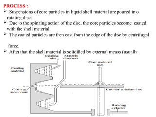
34.
PROCESS :
Suspensionsof core particles in liquid shell material are poured into
rotating disc.
Due to the spinning action of the disc, the core particles become coated
with the shell material.
The coated particles are then cast from the edge of the disc by centrifugal
force.
After that the shell material is solidified by external means (usually
cooling).
35.
PROCESS PARAMETERS
Speedof rotation of cylinder
Conc, Viscosity, Surface tension, Flow rate of both core &
Coating material,
Rate of application of coating material
ADV:
This technology is rapid,
Cost-effective,
Relatively simple with high production efficiency.
Encapsulates both solid and liquid materials
36.
36
5. SPRAY DRYINGAND SPRAY CONGEALING
This tech’s are applicable for both solid & liquid core particles
PRINCIPLE:
In both tech’s core material is dispersed in liquid containing
coating material which is then exposed to particular
environmental conditions
This leads to coating of core material with its simultaneous
solidification.
37.
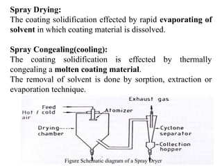
Spray Drying:
The coatingsolidification effected by rapid evaporating of
solvent in which coating material is dissolved.
Spray Congealing(cooling):
The coating solidification is effected by thermally
congealing a molten coating material.
The removal of solvent is done by sorption, extraction or
evaporation technique.
Figure Schematic diagram of a Spray Dryer
38.
38
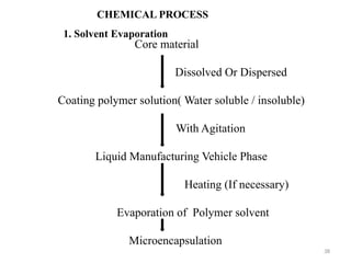
Core material
Dissolved OrDispersed
Coating polymer solution( Water soluble / insoluble)
With Agitation
Liquid Manufacturing Vehicle Phase
Heating (If necessary)
Evaporation of Polymer solvent
Microencapsulation
CHEMICAL PROCESS
1. Solvent Evaporation
39.
2.POLYMERIZATION
Polymerization
It isa process of reacting monomer molecules together in a
chemical reaction to form polymer chains or three-dimensional
network.
Ex: The simplest example involves the formation of
Polyethylene from Ethylene molecules.
Emulsion polymerization
It is a type of radical polymerization that usually starts with
an emulsion incorporating water, monomer, and surfactant.
Water Soluble polymers, such as certain polyvinyl alcohols or
Hydroxyethylcellulose can also be used to act as
emulsifiers/stabilizers.
40.
40
2. POLYMERIZATION
1) Interfacialpolymerization
In Interfacial polymerization, the two reactants in a poly condensation
meet at an interface and react rapidly.
2) In-situ polymerization
In a few microencapsulation processes, the direct polymerization of a
single monomer is carried out on the .particle surface.
Ex: Cellulose fibers are encapsulated in polyethylene while .
immersed in dry toluene.
Usual deposition rates are about 0.5μm/min.
Coating thickness ranges 0.2-75μm.
3) Matrix polymerization
In a number of processes, a core material is imbedded in a polymeric
matrix during formation of the particles.
This process Prepares microcapsules containing protein solutions by
incorporating the protein in the aqueous diamine phase.
National Lead Corporation- utilizing polymerization techniques.
41.
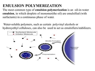
EMULSION POLYMERIZATION
The mostcommon type of emulsion polymerization is an oil-in-water
emulsion, in which droplets of monomer(the oil) are emulsified (with
surfactants) in a continuous phase of water.
Water-soluble polymers, such as certain polyvinyl alcohols or
hydroxyethyl celluloses, can also be used to act as emulsifiers/stabilizers.
42.
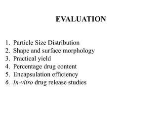
EVALUATION
1. Particle SizeDistribution
2. Shape and surface morphology
3. Practical yield
4. Percentage drug content
5. Encapsulation efficiency
6. In-vitro drug release studies
43.
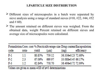
1.PARTICLE SIZE DISTRIBUTION
Different sizes of microcapsules in a batch were separated by
sieve analysis using a range of standard sieves (#10, #22, #44, #52
and # 60).
The amount retained on different sieves was weighed. From the
obtained data, weight Percent retained on different sieves and
average size of microcapsules were calculated.
44.
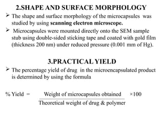
2.SHAPE AND SURFACEMORPHOLOGY
The shape and surface morphology of the microcapsules was
studied by using scanning electron microscope.
Microcapsules were mounted directly onto the SEM sample
stub using double-sided sticking tape and coated with gold film
(thickness 200 nm) under reduced pressure (0.001 mm of Hg).
3.PRACTICAL YIELD
The percentage yield of drug in the microencapsulated product
is determined by using the formula
% Yield = Weight of microcapsules obtained ×100
Theoretical weight of drug & polymer
45.
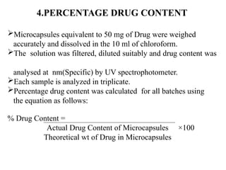
4.PERCENTAGE DRUG CONTENT
Microcapsulesequivalent to 50 mg of Drug were weighed
accurately and dissolved in the 10 ml of chloroform.
The solution was filtered, diluted suitably and drug content was
analysed at nm(Specific) by UV spectrophotometer.
Each sample is analyzed in triplicate.
Percentage drug content was calculated for all batches using
the equation as follows:
% Drug Content =
Actual Drug Content of Microcapsules ×100
Theoretical wt of Drug in Microcapsules
46.
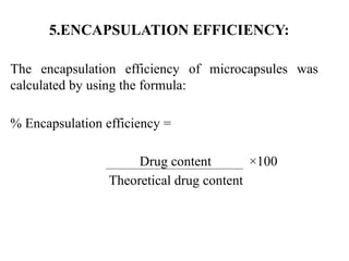
5.ENCAPSULATION EFFICIENCY:
The encapsulationefficiency of microcapsules was
calculated by using the formula:
% Encapsulation efficiency =
Drug content ×100
Theoretical drug content
47.
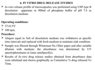
6. IN VITRODRUG RELEASE STUDIES
In-vitro release profile of microcapsules was performed using USP type II
dissolution apparatus in 900ml of phosphate buffer of pH 7.4 as
dissolution medium.
Operating conditions:
37±0.5ºC
100 rpm.
Procedure:
Aliquot equal to 5ml of dissolution medium was withdrawn at specific
time intervals and replaced with fresh medium to maintain sink condition.
Sample was filtered through Whatsman No.1filter paper and after suitable
dilution with medium; the absorbance was determined by UV
spectrophotometer at λmax nm(Specific).
Results of In-vitro drug release studies obtained from absorbance data
were tabulated and shown graphically as Cumulative % drug released Vs
Time.
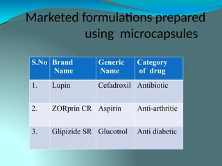
Marketed formulations prepared
usingmicrocapsules
S.No Brand
Name
Generic
Name
Category
of drug
1. Lupin Cefadroxil Antibiotic
2. ZORprin CR Aspirin Anti-arthritic
3. Glipizide SR Glucotrol Anti diabetic