SlideShare a Scribd company logo
1 of 12
Download to read offline
Analog Data Transmission on RF Module Using
Arduino
The transmission of digital data over an RF module is quite common. The 434
RF modules are capable of transmitting 4-bit data along with the address byte.
The circuits using RF modules for digital data transmission are simple and uses
HT12E encoder and HT12D decoder ICs for parallel to serial and serial to
parallel data conversion respectively. In real-life situations, the source of digital
data are only the computers, microcomputers or digital ICs. The real world isn't
the digital, it is analog. Like, the most sensors actually are analog sensors and
they are capable of transmitting the analog data to a digital form only when a
microcomputer process it from analog to digital form.
The Arduino microcontrollers which are most commonly used in hardware
projects are also capable of reading the analog data and representing it to
digital form. The digitization of analog data to a digital form can be performed
using the open-source virtualWire library of the Arduino. The read analog data
can be serially out to an RF transmitter from any digital input/output pin.
This project demonstrates reading the analog data from LDR sensor by an
Arduino board and its transmission to another Arduino board which display the
data in digitized form on an LCD screen.
Components Required -
Sr. no. Name of component Required
quantity
1 RF Tx module(434Mhz) 1
2 RF Rx module(434Mhz) 1
3 LDR 1
4 LCD 1
5 1 K Pot 1
6 10 K resistor 1
7 Arduino pro mini development board 2
8 Battery – 9V 2
9 Bread board 2
10 connecting wires
Block Diagram -
Circuit Diagram -
Circuit Connections -
The analog sensor used in this project is an LDR (Light Dependent Resistor). The
LDR is connected to pin A2 of the Arduino Pro Mini. The LDR sensor is
connected in a pull-up configuration. In this configuration, the LDR is
connected between VCC and the output (A2 pin of Arduino) and a pull-up
resistor of suitable value is connected between output and ground. The read
analog data at pin A2 is serially out from pin 12 (digital I/O pin) of Arduino, so
pin 12 is connected to pin 2 of the RF transmitter. The RF transmitter has an
antenna attached to pin 4 for longer operational range.
At the display side, the serially transmitted data is fetched by an RF receiver.
The pin 2 of receiver is connected to pin 11 of the second Arduino board. An
LCD is interfaced to the Arduino board for displaying the received sensor
reading. The 16X2 LCD display is connected to the Arduino board by connecting
its data pins to pins 7 to 4 of the Arduino board. The RS and RW pin of LCD is
connected to pins 3 and 2 of the Arduino ProMini respectively. The E pin of the
LCD is grounded.
LCD Arduino UNO
RS 3
RW 2
E GRND
D7,D6,D5,D4 7,6,5,4 respectively
The standard code library for interfacing Arduino UNO and Arduino Pro Mini
are used in the project to program LCD with the board.
How the Circuit Works -
The LDR sensor works on the principle of photo-conductivity. Its resistance is
reduced when light falls on it as the resistivity of the sensor is reduced on
exposure to the light. The LDR sensor is connected in pull-up configuration. The
voltage is first dropped by the LDR and then is dropped by the output junction
and pull-up resistor. When light falls on LDR, its resistance is reduced and so
the voltage dropped by the pull-up resistor at the analog data pin is greater.
While when the LDR is covered to restrict its exposure to light, the resistance
value is increased so the voltage dropped by the pull-up resistor at the analog
data pin is reduced. The analog reading is carried out at A2 pin of the Arduino
Pro Mini. It can be done at any pin from A0 to A7 of the Arduino Pro Mini.
The read analog data is stored digitally in a variable in the program code which
is converted to a digitized decimal form using the program logic. The digitized
reading is serially out from pin 12 of the transmitter-side Arduino board to the
RF transmitter.
The digitized reading is detected by the RF receiver and serially out from pin 2
of the receiver to pin 11 of receiver side Arduino board. The reading is
displayed on an LCD screen using the standard library functions of lcd.h in the
program code. The main execution of the project is software oriented so the
program code is the one that needs to be carefully understood.
Programming Guide -
At the transmitter side, Arduino board has to read the analog reading in the
form of voltage dropped at the sensor interfaced pin. For the same, VirtualWire
library is imported.
#include <VirtualWire.h>
An LED has been connected to pin 13 for visual hint of data transmission. A
variable "ledPin" is declared and assigned to pin 13. The LDR sensor is
connected at pin A2, so a variable "Sensor1Pin" is declared and mapped to pin
A2 of Arduino. A variable "Sensor1Data" is declared to fetch analog reading
digitally and "Sensor1CharMsg" array is created for 3-digit precise decimal
representation of the reading.
// LED's
const int ledPin = 13;
// Sensors
const int Sensor1Pin = A2;
int Sensor1Data;
char Sensor1CharMsg[4];
A setup() function is called, inside which, LED interfaced pin is set digital out
and sensor interfaced pin is set to input mode using pinMode() function. The
baud rate of the Arduino is set to 9600 bits per second using Serial.begin
function. The baud rate for serial output is set to 2000 bits per second using
vw_setup() function of the VirtualWire library.
void setup() {
// PinModes
// LED
pinMode(ledPin,OUTPUT);
// Sensor(s)
pinMode(Sensor1Pin,INPUT);
// for debugging
Serial.begin(9600);
// VirtualWire setup
vw_setup(2000); // Bits per sec
}
A loop function is called where the analog data from pin A2 is read using
analogRead() function and assigned to Sensor1Data variable. The Seria1Data
value is converted to decimal form representation and stored in
Sensor1CharMsg array using itoa() integer to character conversion function.
void loop() {
// Read and store Sensor 1 data
Sensor1Data = analogRead(Sensor1Pin);
// Convert integer data to Char array directly
itoa(Sensor1Data,Sensor1CharMsg,10);
The readings stored in both the variable and the array are serially buffered
using Serial.print() function.
// DEBUG
Serial.print("Sensor1 Integer: ");
Serial.print(Sensor1Data);
Serial.print(" Sensor1 CharMsg: ");
Serial.print(Sensor1CharMsg);
Serial.println(" ");
delay(1000);
// END DEBUG
The LED interfaced pin is set to HIGH to glow LED as indication of data
transmission. The reading stored in Sensor1Char array is converted to unsigned
characters till all the four elements of the array are converted to unsigned char
format. The characters are serially out using vw_send function and
vw_wait_tx() function is used to continue transmission until all the data (all
four characters) are serially out from the buffer. The LED is switched OFF as an
indication of data transmission completed.
digitalWrite(13, true); // Turn on a light to show transmitting
vw_send((uint8_t *)Sensor1CharMsg, strlen(Sensor1CharMsg));
vw_wait_tx(); // Wait until the whole message is gone
digitalWrite(13, false); // Turn off a light after transmission
delay(200);
} // END void loop...
At the receiver side, again VirtualWire library is imported to read analog data.
#include <VirtualWire.h>
A ledPin variable is assigned to pin 13 where LED indicating reception of data is
connected. A variable Sensor1Data is declared to read data reading as integer
and Sensor1CharMsg array is created to map the decimal form of data reading.
// LED's
int ledPin = 13;
// Sensors
int Sensor1Data;
// RF Transmission container
char Sensor1CharMsg[4];
A setup function is called, where, baud rate of the receiver side Arduino is set
to 9600 bits per second using the Serial.begin() function. The LED connected
pin is set to digital out.
void setup() {
Serial.begin(9600);
// sets the digital pin as output
pinMode(ledPin, OUTPUT);
The RF transmitter and receiver module does not have Push To Talk pin. They
go inactive when no data is present to transmit or receive respectively.
Therefore vw_set_ptt_inverted(true) is used to configure push to talk polarity
and prompt the receiver to continue receiving data after fetching the first
character. The baud rate for serial input is set to 2000 bits per second using
vw_setup() function. The reception of the data is initiated using vw_rx_start()
function.
// VirtualWire
// Initialise the IO and ISR
// Required for DR3100
vw_set_ptt_inverted(true);
// Bits per sec
vw_setup(2000);
// Start the receiver PLL running
vw_rx_start();
} // END void setup
A loop function is called where the data in the microcontroller's buffer is read
and displayed on the LCD screen. A "buf" array is declared of unsigned char
type to fetch received char bytes and variable "buflen" is declared to store the
length of received buffer data.
void loop(){
uint8_t buf[VW_MAX_MESSAGE_LEN];
uint8_t buflen = VW_MAX_MESSAGE_LEN;
The received character buffer is read using vw_get_message() function and a
counter "i" is initialized. The LED interfaced pin is set to HIGH to indicate that
data has been received and received character buffer is converted to character
data type and stored in Sensor1Msg array.
// Non-blocking
if (vw_get_message(buf, &buflen))
{
int i;
// Turn on a light to show received good message
digitalWrite(13, true);
// Message with a good checksum received, dump it.
for (i = 0; i < buflen; i++)
{
// Fill Sensor1CharMsg Char array with corresponding
// chars from buffer.
Sensor1CharMsg[i] = char(buf[i]);
}
The last character in the array is set to Null character so that if the read buffer
has less than four digits it does not display a garbage value on LCD screen. The
Sensor1Msg array elements are converted to integers and stored in
Sensor1Data array.
// Null terminate the char array
// This needs to be done otherwise problems will occur
// when the incoming messages has less digits than the
// one before.
Sensor1CharMsg[buflen] = '0';
// Convert Sensor1CharMsg Char array to integer
Sensor1Data = atoi(Sensor1CharMsg);
The Sensor1Data array integers are displayed on LCD using Serial.print()
function and LED interfaced pin is set to LOW to switch LED off as visual
indication that data has been successfully read and displayed.
// DEBUG
Serial.print("Sensor 1: ");
Serial.println(Sensor1Data);
// END DEBUG
// Turn off light to and await next message
digitalWrite(13, false);
}
}
The analog reading has been read in the project as the voltage reading at the
analog pin of Arduino Pro Mini. The sensor reading has not been calibrated to
show any real physical quantity like light intensity or luminosity in case of light
based sensor. However, actual reading of a physical quantity can be displayed
through the project by judging the calibration of the sensor with respect to the
physical quantity under measurement. The logic to convert the voltage reading
to the measurement of the physical quantity under observation can be
embedded in the program logic based on the calibration of the sensor.
PROGRAMMING CODE
#include <VirtualWire.h>
// LED's
const int ledPin = 13;
// Sensors
const int Sensor1Pin = A2;
int Sensor1Data;
char Sensor1CharMsg[4];
void setup() {
// PinModes
// LED
pinMode(ledPin,OUTPUT);
// Sensor(s)
pinMode(Sensor1Pin,INPUT);
// for debugging
Serial.begin(9600);
// VirtualWire setup
vw_setup(2000); // Bits per sec
}
// Read and store Sensor 1 data
Sensor1Data = analogRead(Sensor1Pin);
// Convert integer data to Char array directly
itoa(Sensor1Data,Sensor1CharMsg,10);
// DEBUG
Serial.print("Sensor1 Integer: ");
Serial.print(Sensor1Data);
Serial.print(" Sensor1 CharMsg: ");
Serial.print(Sensor1CharMsg);
Serial.println(" ");
delay(1000);
// END DEBUG
digitalWrite(13, true); // Turn on a light to show transmitting
vw_send((uint8_t *)Sensor1CharMsg, strlen(Sensor1CharMsg));
vw_wait_tx(); // Wait until the whole message is gone
digitalWrite(13, false); // Turn off a light after transmission
delay(200);
} // END void loop...
#include <VirtualWire.h>
// LED's
int ledPin = 13;
// Sensors
int Sensor1Data;
// RF Transmission container
char Sensor1CharMsg[4];
void setup() {
Serial.begin(9600);
// sets the digital pin as output
pinMode(ledPin, OUTPUT);
// VirtualWire
// Initialise the IO and ISR
// Required for DR3100
vw_set_ptt_inverted(true);
// Bits per sec
vw_setup(2000);
// Start the receiver PLL running
vw_rx_start();
} // END void setup
void loop(){
uint8_t buf[VW_MAX_MESSAGE_LEN];
uint8_t buflen = VW_MAX_MESSAGE_LEN;
// Non-blocking
if (vw_get_message(buf, &buflen))
{
int i;
// Turn on a light to show received good message
digitalWrite(13, true);
// Message with a good checksum received, dump it.
for (i = 0; i < buflen; i++)
{
// Fill Sensor1CharMsg Char array with corresponding
// chars from buffer.
Sensor1CharMsg[i] = char(buf[i]);
}
// Null terminate the char array
// This needs to be done otherwise problems will occur
// when the incoming messages has less digits than the
// one before.
Sensor1CharMsg[buflen] = '0';
// Convert Sensor1CharMsg Char array to integer
Sensor1Data = atoi(Sensor1CharMsg);
// DEBUG
Serial.print("Sensor 1: ");
Serial.println(Sensor1Data);
// END DEBUG
// Turn off light to and await next message
digitalWrite(13, false);
}
}

More Related Content

What's hot

Ultrasonic radar using 8051
Ultrasonic radar using 8051Ultrasonic radar using 8051
Ultrasonic radar using 8051YOGEESH M
 
REAL TIME HEART BEAT MONITORING SYSTEM USING PIC16F876 MICROCONTROLLER
REAL TIME HEART BEAT MONITORING SYSTEM USING PIC16F876 MICROCONTROLLERREAL TIME HEART BEAT MONITORING SYSTEM USING PIC16F876 MICROCONTROLLER
REAL TIME HEART BEAT MONITORING SYSTEM USING PIC16F876 MICROCONTROLLERVenkata Sai Kalyan Routhu
 
Principles of RF Microwave Power Measurement
Principles of RF Microwave Power MeasurementPrinciples of RF Microwave Power Measurement
Principles of RF Microwave Power MeasurementRobert Kirchhoefer
 
Humidity & Temperature monitoring using arduino
Humidity & Temperature monitoring using arduinoHumidity & Temperature monitoring using arduino
Humidity & Temperature monitoring using arduinoMuhammadJaved191
 
Radar System with Arduino Processor
Radar System with Arduino ProcessorRadar System with Arduino Processor
Radar System with Arduino ProcessorMelek Sönmez
 
Visible light communication
Visible light communicationVisible light communication
Visible light communicationNaveen Sihag
 
M ary psk modulation
M ary psk modulationM ary psk modulation
M ary psk modulationAhmed Diaa
 
FM-Foster - Seeley Discriminator.pptx
FM-Foster - Seeley Discriminator.pptxFM-Foster - Seeley Discriminator.pptx
FM-Foster - Seeley Discriminator.pptxArunChokkalingam
 
DHT11 Digital Temperature and Humidity Sensor
DHT11 Digital Temperature and Humidity SensorDHT11 Digital Temperature and Humidity Sensor
DHT11 Digital Temperature and Humidity SensorRaghav Shetty
 
Radar Using Arduino
Radar Using ArduinoRadar Using Arduino
Radar Using ArduinoGolu Jain
 
MicroStrip Antenna
MicroStrip AntennaMicroStrip Antenna
MicroStrip AntennaTarek Nader
 
Study of Radar System PPT
Study of Radar System PPTStudy of Radar System PPT
Study of Radar System PPTAtul Sharma
 

What's hot (20)

Radar ppt
Radar pptRadar ppt
Radar ppt
 
Rfid security access control system
Rfid security access control systemRfid security access control system
Rfid security access control system
 
Ultrasonic radar using 8051
Ultrasonic radar using 8051Ultrasonic radar using 8051
Ultrasonic radar using 8051
 
REAL TIME HEART BEAT MONITORING SYSTEM USING PIC16F876 MICROCONTROLLER
REAL TIME HEART BEAT MONITORING SYSTEM USING PIC16F876 MICROCONTROLLERREAL TIME HEART BEAT MONITORING SYSTEM USING PIC16F876 MICROCONTROLLER
REAL TIME HEART BEAT MONITORING SYSTEM USING PIC16F876 MICROCONTROLLER
 
Principles of RF Microwave Power Measurement
Principles of RF Microwave Power MeasurementPrinciples of RF Microwave Power Measurement
Principles of RF Microwave Power Measurement
 
Humidity & Temperature monitoring using arduino
Humidity & Temperature monitoring using arduinoHumidity & Temperature monitoring using arduino
Humidity & Temperature monitoring using arduino
 
Radar System with Arduino Processor
Radar System with Arduino ProcessorRadar System with Arduino Processor
Radar System with Arduino Processor
 
Visible light communication
Visible light communicationVisible light communication
Visible light communication
 
Antenna (2)
Antenna (2)Antenna (2)
Antenna (2)
 
Directional couplers 22
Directional couplers 22Directional couplers 22
Directional couplers 22
 
Wi-Fi Esp8266 nodemcu
Wi-Fi Esp8266 nodemcu Wi-Fi Esp8266 nodemcu
Wi-Fi Esp8266 nodemcu
 
M ary psk modulation
M ary psk modulationM ary psk modulation
M ary psk modulation
 
FM-Foster - Seeley Discriminator.pptx
FM-Foster - Seeley Discriminator.pptxFM-Foster - Seeley Discriminator.pptx
FM-Foster - Seeley Discriminator.pptx
 
DHT11 Digital Temperature and Humidity Sensor
DHT11 Digital Temperature and Humidity SensorDHT11 Digital Temperature and Humidity Sensor
DHT11 Digital Temperature and Humidity Sensor
 
Radar Using Arduino
Radar Using ArduinoRadar Using Arduino
Radar Using Arduino
 
Adc dac converter
Adc dac converterAdc dac converter
Adc dac converter
 
Arduino course
Arduino courseArduino course
Arduino course
 
MicroStrip Antenna
MicroStrip AntennaMicroStrip Antenna
MicroStrip Antenna
 
Radar communication
Radar communicationRadar communication
Radar communication
 
Study of Radar System PPT
Study of Radar System PPTStudy of Radar System PPT
Study of Radar System PPT
 

Viewers also liked

Informatique verte des capteurs intelligents à la fouille de données - 2014-1...
Informatique verte des capteurs intelligents à la fouille de données - 2014-1...Informatique verte des capteurs intelligents à la fouille de données - 2014-1...
Informatique verte des capteurs intelligents à la fouille de données - 2014-1...Jérôme Rocheteau
 
Wireless humidity and temperature monitoring system
Wireless humidity and temperature monitoring systemWireless humidity and temperature monitoring system
Wireless humidity and temperature monitoring systemSagar Srivastav
 
Fiche récapitulative des projets réalisés
Fiche récapitulative des projets réalisésFiche récapitulative des projets réalisés
Fiche récapitulative des projets réalisésAmine ZANNED
 
Cours16 ressources pour arduino
Cours16   ressources pour arduinoCours16   ressources pour arduino
Cours16 ressources pour arduinolabsud
 
Présentation de projet de fin d’études
Présentation de projet de fin d’étudesPrésentation de projet de fin d’études
Présentation de projet de fin d’étudesAimen Hajri
 
Présentation microprocesseur finale
Présentation microprocesseur finalePrésentation microprocesseur finale
Présentation microprocesseur finaleMahmoud Masmoudi
 
ARDUINO + LABVIEW : CONTRÔLE DE LA TEMPÉRATURE
ARDUINO + LABVIEW : CONTRÔLE DE LA TEMPÉRATUREARDUINO + LABVIEW : CONTRÔLE DE LA TEMPÉRATURE
ARDUINO + LABVIEW : CONTRÔLE DE LA TEMPÉRATUREHajer Dahech
 
présentation soutenance PFE 2016
présentation soutenance PFE 2016présentation soutenance PFE 2016
présentation soutenance PFE 2016Mohsen Sadok
 
Projet de fin d'etude :Control d’acces par empreintes digitale
Projet de fin d'etude :Control d’acces par empreintes digitaleProjet de fin d'etude :Control d’acces par empreintes digitale
Projet de fin d'etude :Control d’acces par empreintes digitaleAbdo07
 
Présentation arduino
Présentation arduinoPrésentation arduino
Présentation arduinoJeff Simon
 
Story Lab - Sensor Journalism [23-04-2015, Liège]
Story Lab - Sensor Journalism [23-04-2015, Liège]Story Lab - Sensor Journalism [23-04-2015, Liège]
Story Lab - Sensor Journalism [23-04-2015, Liège]Gregory Berger
 
Exemple de-code-oop-avec-labview
Exemple de-code-oop-avec-labviewExemple de-code-oop-avec-labview
Exemple de-code-oop-avec-labviewLuc Desruelle
 
« LabVIEW : programmation et applications » ou comment apprendre à utiliser L...
« LabVIEW : programmation et applications » ou comment apprendre à utiliser L...« LabVIEW : programmation et applications » ou comment apprendre à utiliser L...
« LabVIEW : programmation et applications » ou comment apprendre à utiliser L...Luc Desruelle
 
Techniques de programmation avancée LabVIEW : gestion des données de la local...
Techniques de programmation avancée LabVIEW : gestion des données de la local...Techniques de programmation avancée LabVIEW : gestion des données de la local...
Techniques de programmation avancée LabVIEW : gestion des données de la local...Luc Desruelle
 
Introduction à l'IoT: du capteur à la donnée_Presentation Mix-IT2015
Introduction à l'IoT: du capteur à la donnée_Presentation Mix-IT2015Introduction à l'IoT: du capteur à la donnée_Presentation Mix-IT2015
Introduction à l'IoT: du capteur à la donnée_Presentation Mix-IT2015Sameh BEN FREDJ
 
Yassine Otmane voiture commandée à distance (XBEE)
Yassine Otmane voiture commandée à distance (XBEE)Yassine Otmane voiture commandée à distance (XBEE)
Yassine Otmane voiture commandée à distance (XBEE)Othmane Yassine
 

Viewers also liked (18)

Informatique verte des capteurs intelligents à la fouille de données - 2014-1...
Informatique verte des capteurs intelligents à la fouille de données - 2014-1...Informatique verte des capteurs intelligents à la fouille de données - 2014-1...
Informatique verte des capteurs intelligents à la fouille de données - 2014-1...
 
Wireless humidity and temperature monitoring system
Wireless humidity and temperature monitoring systemWireless humidity and temperature monitoring system
Wireless humidity and temperature monitoring system
 
Fiche récapitulative des projets réalisés
Fiche récapitulative des projets réalisésFiche récapitulative des projets réalisés
Fiche récapitulative des projets réalisés
 
Cours16 ressources pour arduino
Cours16   ressources pour arduinoCours16   ressources pour arduino
Cours16 ressources pour arduino
 
Présentation de projet de fin d’études
Présentation de projet de fin d’étudesPrésentation de projet de fin d’études
Présentation de projet de fin d’études
 
Présentation microprocesseur finale
Présentation microprocesseur finalePrésentation microprocesseur finale
Présentation microprocesseur finale
 
ARDUINO + LABVIEW : CONTRÔLE DE LA TEMPÉRATURE
ARDUINO + LABVIEW : CONTRÔLE DE LA TEMPÉRATUREARDUINO + LABVIEW : CONTRÔLE DE LA TEMPÉRATURE
ARDUINO + LABVIEW : CONTRÔLE DE LA TEMPÉRATURE
 
présentation soutenance PFE 2016
présentation soutenance PFE 2016présentation soutenance PFE 2016
présentation soutenance PFE 2016
 
Projet de fin d'etude :Control d’acces par empreintes digitale
Projet de fin d'etude :Control d’acces par empreintes digitaleProjet de fin d'etude :Control d’acces par empreintes digitale
Projet de fin d'etude :Control d’acces par empreintes digitale
 
Les systèmes embarqués arduino
Les systèmes embarqués arduinoLes systèmes embarqués arduino
Les systèmes embarqués arduino
 
Présentation arduino
Présentation arduinoPrésentation arduino
Présentation arduino
 
Story Lab - Sensor Journalism [23-04-2015, Liège]
Story Lab - Sensor Journalism [23-04-2015, Liège]Story Lab - Sensor Journalism [23-04-2015, Liège]
Story Lab - Sensor Journalism [23-04-2015, Liège]
 
Exemple de-code-oop-avec-labview
Exemple de-code-oop-avec-labviewExemple de-code-oop-avec-labview
Exemple de-code-oop-avec-labview
 
« LabVIEW : programmation et applications » ou comment apprendre à utiliser L...
« LabVIEW : programmation et applications » ou comment apprendre à utiliser L...« LabVIEW : programmation et applications » ou comment apprendre à utiliser L...
« LabVIEW : programmation et applications » ou comment apprendre à utiliser L...
 
Techniques de programmation avancée LabVIEW : gestion des données de la local...
Techniques de programmation avancée LabVIEW : gestion des données de la local...Techniques de programmation avancée LabVIEW : gestion des données de la local...
Techniques de programmation avancée LabVIEW : gestion des données de la local...
 
Introduction à l'IoT: du capteur à la donnée_Presentation Mix-IT2015
Introduction à l'IoT: du capteur à la donnée_Presentation Mix-IT2015Introduction à l'IoT: du capteur à la donnée_Presentation Mix-IT2015
Introduction à l'IoT: du capteur à la donnée_Presentation Mix-IT2015
 
Yassine Otmane voiture commandée à distance (XBEE)
Yassine Otmane voiture commandée à distance (XBEE)Yassine Otmane voiture commandée à distance (XBEE)
Yassine Otmane voiture commandée à distance (XBEE)
 
LabVIEW™ real time programing
LabVIEW™ real time programingLabVIEW™ real time programing
LabVIEW™ real time programing
 

Similar to Analog data transmission on rf module using arduino

WIRELESS GESTURED CONTROLLED ROBOT USING ACCELEROMETER
WIRELESS GESTURED CONTROLLED ROBOT USING ACCELEROMETERWIRELESS GESTURED CONTROLLED ROBOT USING ACCELEROMETER
WIRELESS GESTURED CONTROLLED ROBOT USING ACCELEROMETERLOKENDAR KUMAR
 
INT4073 L07(Sensors and AcutTORS).pdf
INT4073 L07(Sensors and AcutTORS).pdfINT4073 L07(Sensors and AcutTORS).pdf
INT4073 L07(Sensors and AcutTORS).pdfMSingh88
 
Internet of things laboratory
Internet of things laboratoryInternet of things laboratory
Internet of things laboratorySoumee Maschatak
 
Data Encoding for Wireless Transmission
Data Encoding for Wireless TransmissionData Encoding for Wireless Transmission
Data Encoding for Wireless TransmissionSean McQuay
 
Radio frequency identification system
Radio frequency identification systemRadio frequency identification system
Radio frequency identification systemAminu Bugaje
 
Transmitting Digital Signal through Light Pulses
Transmitting Digital Signal through Light PulsesTransmitting Digital Signal through Light Pulses
Transmitting Digital Signal through Light PulsesKarthik Rathinavel
 
Arduino projects &amp; tutorials
Arduino projects &amp; tutorialsArduino projects &amp; tutorials
Arduino projects &amp; tutorialsAnshu Pandey
 
Monitoring temperature rumah dengan display lcd dan recording
Monitoring temperature rumah dengan display lcd dan recordingMonitoring temperature rumah dengan display lcd dan recording
Monitoring temperature rumah dengan display lcd dan recordingMR Selamet
 
Monitoring temperature ruangan dengan display lcd
Monitoring temperature ruangan dengan display lcdMonitoring temperature ruangan dengan display lcd
Monitoring temperature ruangan dengan display lcdsiti_haryani
 
Monitoring temperature rumah dengan display lcd dan recording
Monitoring temperature rumah dengan display lcd dan recordingMonitoring temperature rumah dengan display lcd dan recording
Monitoring temperature rumah dengan display lcd dan recordingYuda Wardiana
 
Fire Fighter Robot with Night Vision Camera (1).pptx
Fire Fighter Robot with Night Vision Camera (1).pptxFire Fighter Robot with Night Vision Camera (1).pptx
Fire Fighter Robot with Night Vision Camera (1).pptxSyedMohiuddin62
 
accelerometer based robot.pptx
accelerometer based robot.pptxaccelerometer based robot.pptx
accelerometer based robot.pptxKishor Mhaske
 
Monitoring Temperature Room With Display LCD and Data Recording
Monitoring Temperature Room With Display LCD and Data RecordingMonitoring Temperature Room With Display LCD and Data Recording
Monitoring Temperature Room With Display LCD and Data RecordingMR Selamet
 
Monitoring temperature ruangan dengan display lcd
Monitoring temperature ruangan dengan display lcdMonitoring temperature ruangan dengan display lcd
Monitoring temperature ruangan dengan display lcdmukhammadimam
 
Physical prototyping lab2-analog_digital
Physical prototyping lab2-analog_digitalPhysical prototyping lab2-analog_digital
Physical prototyping lab2-analog_digitalTony Olsson.
 
Physical prototyping lab2-analog_digital
Physical prototyping lab2-analog_digitalPhysical prototyping lab2-analog_digital
Physical prototyping lab2-analog_digitalTony Olsson.
 
I2c interfacing raspberry pi to arduino
I2c interfacing raspberry pi to arduinoI2c interfacing raspberry pi to arduino
I2c interfacing raspberry pi to arduinoMike Ochtman
 

Similar to Analog data transmission on rf module using arduino (20)

WIRELESS GESTURED CONTROLLED ROBOT USING ACCELEROMETER
WIRELESS GESTURED CONTROLLED ROBOT USING ACCELEROMETERWIRELESS GESTURED CONTROLLED ROBOT USING ACCELEROMETER
WIRELESS GESTURED CONTROLLED ROBOT USING ACCELEROMETER
 
INT4073 L07(Sensors and AcutTORS).pdf
INT4073 L07(Sensors and AcutTORS).pdfINT4073 L07(Sensors and AcutTORS).pdf
INT4073 L07(Sensors and AcutTORS).pdf
 
Internet of things laboratory
Internet of things laboratoryInternet of things laboratory
Internet of things laboratory
 
Data Encoding for Wireless Transmission
Data Encoding for Wireless TransmissionData Encoding for Wireless Transmission
Data Encoding for Wireless Transmission
 
Radio frequency identification system
Radio frequency identification systemRadio frequency identification system
Radio frequency identification system
 
ARDUINO (1).pdf
ARDUINO (1).pdfARDUINO (1).pdf
ARDUINO (1).pdf
 
Ju2416921695
Ju2416921695Ju2416921695
Ju2416921695
 
Arduino
ArduinoArduino
Arduino
 
Transmitting Digital Signal through Light Pulses
Transmitting Digital Signal through Light PulsesTransmitting Digital Signal through Light Pulses
Transmitting Digital Signal through Light Pulses
 
Arduino projects &amp; tutorials
Arduino projects &amp; tutorialsArduino projects &amp; tutorials
Arduino projects &amp; tutorials
 
Monitoring temperature rumah dengan display lcd dan recording
Monitoring temperature rumah dengan display lcd dan recordingMonitoring temperature rumah dengan display lcd dan recording
Monitoring temperature rumah dengan display lcd dan recording
 
Monitoring temperature ruangan dengan display lcd
Monitoring temperature ruangan dengan display lcdMonitoring temperature ruangan dengan display lcd
Monitoring temperature ruangan dengan display lcd
 
Monitoring temperature rumah dengan display lcd dan recording
Monitoring temperature rumah dengan display lcd dan recordingMonitoring temperature rumah dengan display lcd dan recording
Monitoring temperature rumah dengan display lcd dan recording
 
Fire Fighter Robot with Night Vision Camera (1).pptx
Fire Fighter Robot with Night Vision Camera (1).pptxFire Fighter Robot with Night Vision Camera (1).pptx
Fire Fighter Robot with Night Vision Camera (1).pptx
 
accelerometer based robot.pptx
accelerometer based robot.pptxaccelerometer based robot.pptx
accelerometer based robot.pptx
 
Monitoring Temperature Room With Display LCD and Data Recording
Monitoring Temperature Room With Display LCD and Data RecordingMonitoring Temperature Room With Display LCD and Data Recording
Monitoring Temperature Room With Display LCD and Data Recording
 
Monitoring temperature ruangan dengan display lcd
Monitoring temperature ruangan dengan display lcdMonitoring temperature ruangan dengan display lcd
Monitoring temperature ruangan dengan display lcd
 
Physical prototyping lab2-analog_digital
Physical prototyping lab2-analog_digitalPhysical prototyping lab2-analog_digital
Physical prototyping lab2-analog_digital
 
Physical prototyping lab2-analog_digital
Physical prototyping lab2-analog_digitalPhysical prototyping lab2-analog_digital
Physical prototyping lab2-analog_digital
 
I2c interfacing raspberry pi to arduino
I2c interfacing raspberry pi to arduinoI2c interfacing raspberry pi to arduino
I2c interfacing raspberry pi to arduino
 

Recently uploaded

Industrial Safety Unit-IV workplace health and safety.ppt
Industrial Safety Unit-IV workplace health and safety.pptIndustrial Safety Unit-IV workplace health and safety.ppt
Industrial Safety Unit-IV workplace health and safety.pptNarmatha D
 
Introduction to Machine Learning Unit-3 for II MECH
Introduction to Machine Learning Unit-3 for II MECHIntroduction to Machine Learning Unit-3 for II MECH
Introduction to Machine Learning Unit-3 for II MECHC Sai Kiran
 
Arduino_CSE ece ppt for working and principal of arduino.ppt
Arduino_CSE ece ppt for working and principal of arduino.pptArduino_CSE ece ppt for working and principal of arduino.ppt
Arduino_CSE ece ppt for working and principal of arduino.pptSAURABHKUMAR892774
 
Concrete Mix Design - IS 10262-2019 - .pptx
Concrete Mix Design - IS 10262-2019 - .pptxConcrete Mix Design - IS 10262-2019 - .pptx
Concrete Mix Design - IS 10262-2019 - .pptxKartikeyaDwivedi3
 
An experimental study in using natural admixture as an alternative for chemic...
An experimental study in using natural admixture as an alternative for chemic...An experimental study in using natural admixture as an alternative for chemic...
An experimental study in using natural admixture as an alternative for chemic...Chandu841456
 
Transport layer issues and challenges - Guide
Transport layer issues and challenges - GuideTransport layer issues and challenges - Guide
Transport layer issues and challenges - GuideGOPINATHS437943
 
Unit7-DC_Motors nkkjnsdkfnfcdfknfdgfggfg
Unit7-DC_Motors nkkjnsdkfnfcdfknfdgfggfgUnit7-DC_Motors nkkjnsdkfnfcdfknfdgfggfg
Unit7-DC_Motors nkkjnsdkfnfcdfknfdgfggfgsaravananr517913
 
Solving The Right Triangles PowerPoint 2.ppt
Solving The Right Triangles PowerPoint 2.pptSolving The Right Triangles PowerPoint 2.ppt
Solving The Right Triangles PowerPoint 2.pptJasonTagapanGulla
 
Mine Environment II Lab_MI10448MI__________.pptx
Mine Environment II Lab_MI10448MI__________.pptxMine Environment II Lab_MI10448MI__________.pptx
Mine Environment II Lab_MI10448MI__________.pptxRomil Mishra
 
Gurgaon ✡️9711147426✨Call In girls Gurgaon Sector 51 escort service
Gurgaon ✡️9711147426✨Call In girls Gurgaon Sector 51 escort serviceGurgaon ✡️9711147426✨Call In girls Gurgaon Sector 51 escort service
Gurgaon ✡️9711147426✨Call In girls Gurgaon Sector 51 escort servicejennyeacort
 
Software and Systems Engineering Standards: Verification and Validation of Sy...
Software and Systems Engineering Standards: Verification and Validation of Sy...Software and Systems Engineering Standards: Verification and Validation of Sy...
Software and Systems Engineering Standards: Verification and Validation of Sy...VICTOR MAESTRE RAMIREZ
 
Input Output Management in Operating System
Input Output Management in Operating SystemInput Output Management in Operating System
Input Output Management in Operating SystemRashmi Bhat
 
NO1 Certified Black Magic Specialist Expert Amil baba in Uae Dubai Abu Dhabi ...
NO1 Certified Black Magic Specialist Expert Amil baba in Uae Dubai Abu Dhabi ...NO1 Certified Black Magic Specialist Expert Amil baba in Uae Dubai Abu Dhabi ...
NO1 Certified Black Magic Specialist Expert Amil baba in Uae Dubai Abu Dhabi ...Amil Baba Dawood bangali
 
National Level Hackathon Participation Certificate.pdf
National Level Hackathon Participation Certificate.pdfNational Level Hackathon Participation Certificate.pdf
National Level Hackathon Participation Certificate.pdfRajuKanojiya4
 
US Department of Education FAFSA Week of Action
US Department of Education FAFSA Week of ActionUS Department of Education FAFSA Week of Action
US Department of Education FAFSA Week of ActionMebane Rash
 
CCS355 Neural Networks & Deep Learning Unit 1 PDF notes with Question bank .pdf
CCS355 Neural Networks & Deep Learning Unit 1 PDF notes with Question bank .pdfCCS355 Neural Networks & Deep Learning Unit 1 PDF notes with Question bank .pdf
CCS355 Neural Networks & Deep Learning Unit 1 PDF notes with Question bank .pdfAsst.prof M.Gokilavani
 
Research Methodology for Engineering pdf
Research Methodology for Engineering pdfResearch Methodology for Engineering pdf
Research Methodology for Engineering pdfCaalaaAbdulkerim
 

Recently uploaded (20)

Industrial Safety Unit-IV workplace health and safety.ppt
Industrial Safety Unit-IV workplace health and safety.pptIndustrial Safety Unit-IV workplace health and safety.ppt
Industrial Safety Unit-IV workplace health and safety.ppt
 
Introduction to Machine Learning Unit-3 for II MECH
Introduction to Machine Learning Unit-3 for II MECHIntroduction to Machine Learning Unit-3 for II MECH
Introduction to Machine Learning Unit-3 for II MECH
 
Arduino_CSE ece ppt for working and principal of arduino.ppt
Arduino_CSE ece ppt for working and principal of arduino.pptArduino_CSE ece ppt for working and principal of arduino.ppt
Arduino_CSE ece ppt for working and principal of arduino.ppt
 
Concrete Mix Design - IS 10262-2019 - .pptx
Concrete Mix Design - IS 10262-2019 - .pptxConcrete Mix Design - IS 10262-2019 - .pptx
Concrete Mix Design - IS 10262-2019 - .pptx
 
An experimental study in using natural admixture as an alternative for chemic...
An experimental study in using natural admixture as an alternative for chemic...An experimental study in using natural admixture as an alternative for chemic...
An experimental study in using natural admixture as an alternative for chemic...
 
Transport layer issues and challenges - Guide
Transport layer issues and challenges - GuideTransport layer issues and challenges - Guide
Transport layer issues and challenges - Guide
 
Unit7-DC_Motors nkkjnsdkfnfcdfknfdgfggfg
Unit7-DC_Motors nkkjnsdkfnfcdfknfdgfggfgUnit7-DC_Motors nkkjnsdkfnfcdfknfdgfggfg
Unit7-DC_Motors nkkjnsdkfnfcdfknfdgfggfg
 
Solving The Right Triangles PowerPoint 2.ppt
Solving The Right Triangles PowerPoint 2.pptSolving The Right Triangles PowerPoint 2.ppt
Solving The Right Triangles PowerPoint 2.ppt
 
Mine Environment II Lab_MI10448MI__________.pptx
Mine Environment II Lab_MI10448MI__________.pptxMine Environment II Lab_MI10448MI__________.pptx
Mine Environment II Lab_MI10448MI__________.pptx
 
🔝9953056974🔝!!-YOUNG call girls in Rajendra Nagar Escort rvice Shot 2000 nigh...
🔝9953056974🔝!!-YOUNG call girls in Rajendra Nagar Escort rvice Shot 2000 nigh...🔝9953056974🔝!!-YOUNG call girls in Rajendra Nagar Escort rvice Shot 2000 nigh...
🔝9953056974🔝!!-YOUNG call girls in Rajendra Nagar Escort rvice Shot 2000 nigh...
 
Gurgaon ✡️9711147426✨Call In girls Gurgaon Sector 51 escort service
Gurgaon ✡️9711147426✨Call In girls Gurgaon Sector 51 escort serviceGurgaon ✡️9711147426✨Call In girls Gurgaon Sector 51 escort service
Gurgaon ✡️9711147426✨Call In girls Gurgaon Sector 51 escort service
 
young call girls in Green Park🔝 9953056974 🔝 escort Service
young call girls in Green Park🔝 9953056974 🔝 escort Serviceyoung call girls in Green Park🔝 9953056974 🔝 escort Service
young call girls in Green Park🔝 9953056974 🔝 escort Service
 
Software and Systems Engineering Standards: Verification and Validation of Sy...
Software and Systems Engineering Standards: Verification and Validation of Sy...Software and Systems Engineering Standards: Verification and Validation of Sy...
Software and Systems Engineering Standards: Verification and Validation of Sy...
 
Input Output Management in Operating System
Input Output Management in Operating SystemInput Output Management in Operating System
Input Output Management in Operating System
 
NO1 Certified Black Magic Specialist Expert Amil baba in Uae Dubai Abu Dhabi ...
NO1 Certified Black Magic Specialist Expert Amil baba in Uae Dubai Abu Dhabi ...NO1 Certified Black Magic Specialist Expert Amil baba in Uae Dubai Abu Dhabi ...
NO1 Certified Black Magic Specialist Expert Amil baba in Uae Dubai Abu Dhabi ...
 
National Level Hackathon Participation Certificate.pdf
National Level Hackathon Participation Certificate.pdfNational Level Hackathon Participation Certificate.pdf
National Level Hackathon Participation Certificate.pdf
 
US Department of Education FAFSA Week of Action
US Department of Education FAFSA Week of ActionUS Department of Education FAFSA Week of Action
US Department of Education FAFSA Week of Action
 
young call girls in Rajiv Chowk🔝 9953056974 🔝 Delhi escort Service
young call girls in Rajiv Chowk🔝 9953056974 🔝 Delhi escort Serviceyoung call girls in Rajiv Chowk🔝 9953056974 🔝 Delhi escort Service
young call girls in Rajiv Chowk🔝 9953056974 🔝 Delhi escort Service
 
CCS355 Neural Networks & Deep Learning Unit 1 PDF notes with Question bank .pdf
CCS355 Neural Networks & Deep Learning Unit 1 PDF notes with Question bank .pdfCCS355 Neural Networks & Deep Learning Unit 1 PDF notes with Question bank .pdf
CCS355 Neural Networks & Deep Learning Unit 1 PDF notes with Question bank .pdf
 
Research Methodology for Engineering pdf
Research Methodology for Engineering pdfResearch Methodology for Engineering pdf
Research Methodology for Engineering pdf
 

Analog data transmission on rf module using arduino

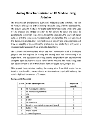
  • 1. Analog Data Transmission on RF Module Using Arduino The transmission of digital data over an RF module is quite common. The 434 RF modules are capable of transmitting 4-bit data along with the address byte. The circuits using RF modules for digital data transmission are simple and uses HT12E encoder and HT12D decoder ICs for parallel to serial and serial to parallel data conversion respectively. In real-life situations, the source of digital data are only the computers, microcomputers or digital ICs. The real world isn't the digital, it is analog. Like, the most sensors actually are analog sensors and they are capable of transmitting the analog data to a digital form only when a microcomputer process it from analog to digital form. The Arduino microcontrollers which are most commonly used in hardware projects are also capable of reading the analog data and representing it to digital form. The digitization of analog data to a digital form can be performed using the open-source virtualWire library of the Arduino. The read analog data can be serially out to an RF transmitter from any digital input/output pin. This project demonstrates reading the analog data from LDR sensor by an Arduino board and its transmission to another Arduino board which display the data in digitized form on an LCD screen. Components Required - Sr. no. Name of component Required quantity 1 RF Tx module(434Mhz) 1 2 RF Rx module(434Mhz) 1 3 LDR 1 4 LCD 1 5 1 K Pot 1 6 10 K resistor 1 7 Arduino pro mini development board 2 8 Battery – 9V 2 9 Bread board 2 10 connecting wires
  • 2. Block Diagram - Circuit Diagram - Circuit Connections - The analog sensor used in this project is an LDR (Light Dependent Resistor). The LDR is connected to pin A2 of the Arduino Pro Mini. The LDR sensor is connected in a pull-up configuration. In this configuration, the LDR is connected between VCC and the output (A2 pin of Arduino) and a pull-up resistor of suitable value is connected between output and ground. The read analog data at pin A2 is serially out from pin 12 (digital I/O pin) of Arduino, so pin 12 is connected to pin 2 of the RF transmitter. The RF transmitter has an antenna attached to pin 4 for longer operational range.
  • 3. At the display side, the serially transmitted data is fetched by an RF receiver. The pin 2 of receiver is connected to pin 11 of the second Arduino board. An LCD is interfaced to the Arduino board for displaying the received sensor reading. The 16X2 LCD display is connected to the Arduino board by connecting its data pins to pins 7 to 4 of the Arduino board. The RS and RW pin of LCD is connected to pins 3 and 2 of the Arduino ProMini respectively. The E pin of the LCD is grounded. LCD Arduino UNO RS 3 RW 2 E GRND D7,D6,D5,D4 7,6,5,4 respectively The standard code library for interfacing Arduino UNO and Arduino Pro Mini are used in the project to program LCD with the board.
  • 4. How the Circuit Works - The LDR sensor works on the principle of photo-conductivity. Its resistance is reduced when light falls on it as the resistivity of the sensor is reduced on exposure to the light. The LDR sensor is connected in pull-up configuration. The voltage is first dropped by the LDR and then is dropped by the output junction and pull-up resistor. When light falls on LDR, its resistance is reduced and so the voltage dropped by the pull-up resistor at the analog data pin is greater. While when the LDR is covered to restrict its exposure to light, the resistance value is increased so the voltage dropped by the pull-up resistor at the analog data pin is reduced. The analog reading is carried out at A2 pin of the Arduino Pro Mini. It can be done at any pin from A0 to A7 of the Arduino Pro Mini. The read analog data is stored digitally in a variable in the program code which is converted to a digitized decimal form using the program logic. The digitized reading is serially out from pin 12 of the transmitter-side Arduino board to the RF transmitter.
  • 5. The digitized reading is detected by the RF receiver and serially out from pin 2 of the receiver to pin 11 of receiver side Arduino board. The reading is displayed on an LCD screen using the standard library functions of lcd.h in the program code. The main execution of the project is software oriented so the program code is the one that needs to be carefully understood. Programming Guide - At the transmitter side, Arduino board has to read the analog reading in the form of voltage dropped at the sensor interfaced pin. For the same, VirtualWire library is imported. #include <VirtualWire.h> An LED has been connected to pin 13 for visual hint of data transmission. A variable "ledPin" is declared and assigned to pin 13. The LDR sensor is connected at pin A2, so a variable "Sensor1Pin" is declared and mapped to pin A2 of Arduino. A variable "Sensor1Data" is declared to fetch analog reading digitally and "Sensor1CharMsg" array is created for 3-digit precise decimal representation of the reading. // LED's const int ledPin = 13; // Sensors const int Sensor1Pin = A2; int Sensor1Data; char Sensor1CharMsg[4]; A setup() function is called, inside which, LED interfaced pin is set digital out and sensor interfaced pin is set to input mode using pinMode() function. The baud rate of the Arduino is set to 9600 bits per second using Serial.begin function. The baud rate for serial output is set to 2000 bits per second using vw_setup() function of the VirtualWire library. void setup() { // PinModes // LED pinMode(ledPin,OUTPUT); // Sensor(s) pinMode(Sensor1Pin,INPUT); // for debugging
  • 6. Serial.begin(9600); // VirtualWire setup vw_setup(2000); // Bits per sec } A loop function is called where the analog data from pin A2 is read using analogRead() function and assigned to Sensor1Data variable. The Seria1Data value is converted to decimal form representation and stored in Sensor1CharMsg array using itoa() integer to character conversion function. void loop() { // Read and store Sensor 1 data Sensor1Data = analogRead(Sensor1Pin); // Convert integer data to Char array directly itoa(Sensor1Data,Sensor1CharMsg,10); The readings stored in both the variable and the array are serially buffered using Serial.print() function. // DEBUG Serial.print("Sensor1 Integer: "); Serial.print(Sensor1Data); Serial.print(" Sensor1 CharMsg: "); Serial.print(Sensor1CharMsg); Serial.println(" "); delay(1000); // END DEBUG The LED interfaced pin is set to HIGH to glow LED as indication of data transmission. The reading stored in Sensor1Char array is converted to unsigned characters till all the four elements of the array are converted to unsigned char format. The characters are serially out using vw_send function and vw_wait_tx() function is used to continue transmission until all the data (all four characters) are serially out from the buffer. The LED is switched OFF as an indication of data transmission completed. digitalWrite(13, true); // Turn on a light to show transmitting vw_send((uint8_t *)Sensor1CharMsg, strlen(Sensor1CharMsg)); vw_wait_tx(); // Wait until the whole message is gone digitalWrite(13, false); // Turn off a light after transmission delay(200);
  • 7. } // END void loop... At the receiver side, again VirtualWire library is imported to read analog data. #include <VirtualWire.h> A ledPin variable is assigned to pin 13 where LED indicating reception of data is connected. A variable Sensor1Data is declared to read data reading as integer and Sensor1CharMsg array is created to map the decimal form of data reading. // LED's int ledPin = 13; // Sensors int Sensor1Data; // RF Transmission container char Sensor1CharMsg[4]; A setup function is called, where, baud rate of the receiver side Arduino is set to 9600 bits per second using the Serial.begin() function. The LED connected pin is set to digital out. void setup() { Serial.begin(9600); // sets the digital pin as output pinMode(ledPin, OUTPUT); The RF transmitter and receiver module does not have Push To Talk pin. They go inactive when no data is present to transmit or receive respectively. Therefore vw_set_ptt_inverted(true) is used to configure push to talk polarity and prompt the receiver to continue receiving data after fetching the first character. The baud rate for serial input is set to 2000 bits per second using vw_setup() function. The reception of the data is initiated using vw_rx_start() function. // VirtualWire // Initialise the IO and ISR // Required for DR3100 vw_set_ptt_inverted(true); // Bits per sec vw_setup(2000); // Start the receiver PLL running vw_rx_start();
  • 8. } // END void setup A loop function is called where the data in the microcontroller's buffer is read and displayed on the LCD screen. A "buf" array is declared of unsigned char type to fetch received char bytes and variable "buflen" is declared to store the length of received buffer data. void loop(){ uint8_t buf[VW_MAX_MESSAGE_LEN]; uint8_t buflen = VW_MAX_MESSAGE_LEN; The received character buffer is read using vw_get_message() function and a counter "i" is initialized. The LED interfaced pin is set to HIGH to indicate that data has been received and received character buffer is converted to character data type and stored in Sensor1Msg array. // Non-blocking if (vw_get_message(buf, &buflen)) { int i; // Turn on a light to show received good message digitalWrite(13, true); // Message with a good checksum received, dump it. for (i = 0; i < buflen; i++) { // Fill Sensor1CharMsg Char array with corresponding // chars from buffer. Sensor1CharMsg[i] = char(buf[i]); } The last character in the array is set to Null character so that if the read buffer has less than four digits it does not display a garbage value on LCD screen. The Sensor1Msg array elements are converted to integers and stored in Sensor1Data array. // Null terminate the char array // This needs to be done otherwise problems will occur // when the incoming messages has less digits than the // one before. Sensor1CharMsg[buflen] = '0'; // Convert Sensor1CharMsg Char array to integer
  • 9. Sensor1Data = atoi(Sensor1CharMsg); The Sensor1Data array integers are displayed on LCD using Serial.print() function and LED interfaced pin is set to LOW to switch LED off as visual indication that data has been successfully read and displayed. // DEBUG Serial.print("Sensor 1: "); Serial.println(Sensor1Data); // END DEBUG // Turn off light to and await next message digitalWrite(13, false); } } The analog reading has been read in the project as the voltage reading at the analog pin of Arduino Pro Mini. The sensor reading has not been calibrated to show any real physical quantity like light intensity or luminosity in case of light based sensor. However, actual reading of a physical quantity can be displayed through the project by judging the calibration of the sensor with respect to the physical quantity under measurement. The logic to convert the voltage reading to the measurement of the physical quantity under observation can be embedded in the program logic based on the calibration of the sensor. PROGRAMMING CODE #include <VirtualWire.h> // LED's const int ledPin = 13; // Sensors const int Sensor1Pin = A2; int Sensor1Data; char Sensor1CharMsg[4]; void setup() { // PinModes
  • 10. // LED pinMode(ledPin,OUTPUT); // Sensor(s) pinMode(Sensor1Pin,INPUT); // for debugging Serial.begin(9600); // VirtualWire setup vw_setup(2000); // Bits per sec } // Read and store Sensor 1 data Sensor1Data = analogRead(Sensor1Pin); // Convert integer data to Char array directly itoa(Sensor1Data,Sensor1CharMsg,10); // DEBUG Serial.print("Sensor1 Integer: "); Serial.print(Sensor1Data); Serial.print(" Sensor1 CharMsg: "); Serial.print(Sensor1CharMsg); Serial.println(" "); delay(1000); // END DEBUG digitalWrite(13, true); // Turn on a light to show transmitting vw_send((uint8_t *)Sensor1CharMsg, strlen(Sensor1CharMsg)); vw_wait_tx(); // Wait until the whole message is gone digitalWrite(13, false); // Turn off a light after transmission delay(200); } // END void loop... #include <VirtualWire.h> // LED's int ledPin = 13; // Sensors int Sensor1Data; // RF Transmission container char Sensor1CharMsg[4]; void setup() {
  • 11. Serial.begin(9600); // sets the digital pin as output pinMode(ledPin, OUTPUT); // VirtualWire // Initialise the IO and ISR // Required for DR3100 vw_set_ptt_inverted(true); // Bits per sec vw_setup(2000); // Start the receiver PLL running vw_rx_start(); } // END void setup void loop(){ uint8_t buf[VW_MAX_MESSAGE_LEN]; uint8_t buflen = VW_MAX_MESSAGE_LEN; // Non-blocking if (vw_get_message(buf, &buflen)) { int i; // Turn on a light to show received good message digitalWrite(13, true); // Message with a good checksum received, dump it. for (i = 0; i < buflen; i++) { // Fill Sensor1CharMsg Char array with corresponding // chars from buffer. Sensor1CharMsg[i] = char(buf[i]); } // Null terminate the char array // This needs to be done otherwise problems will occur // when the incoming messages has less digits than the // one before. Sensor1CharMsg[buflen] = '0'; // Convert Sensor1CharMsg Char array to integer Sensor1Data = atoi(Sensor1CharMsg);
  • 12. // DEBUG Serial.print("Sensor 1: "); Serial.println(Sensor1Data); // END DEBUG // Turn off light to and await next message digitalWrite(13, false); } }