
Recommended
More Related Content
What's hot
What's hot (20)
Similar to X-Ray Physics and Components
Similar to X-Ray Physics and Components (20)
Recently uploaded
Recently uploaded (20)
X-Ray Physics and Components
- 2. Contents- Introduction History Basic Physics of Radiation Continuous Spectrum X-ray tube
- 3. Wilhelm Conrad Roentgen (1845-1923) German scientist Wilhelm Roentgen who discovered these on November 8, 1895, who usually is credited as its discoverer, and who named it X-radiation to signify an unknown type of radiation.
- 4. The first x-ray photograph: Roentgen’s wife Bertha’s hand
- 5. Basic x-ray physics :- X-rays: a form of electromagnetic energy Travel at the speed of light Electromagnetic spectrum Gamma Rays X-rays Ultraviolet Visible light Infrared light Microwaves Radio waves Radar
- 7. Continuous Spectrum X-rays are produced whenever matter is irradiated with a beam of high-energy charged particles or photons In an x-ray tube, the interactions are between the electrons and the target. Since energy must be conserved, the energy loss from the interaction results in the release of x-ray photons The energy (wavelength) will be equal to the energy loss (Equation 4). This process generates a broad band of continuous radiation (a.k.a. bremsstrahlung or white radiation)
- 8. Continuous Spectrum The minimum wavelength ( in angstroms) is dependent on the accelerating potential ( in KV) of the electrons, by the equation above. The continuum reaches a maximum intensity at a wavelength of about 1.5 to 2 times the min as indicated by the shape of the curve VV hc 398.12 min
- 9. Generating Characteristic Radiation The photoelectric effect is responsible for generation of characteristic x-rays. Qualitatively here’s what is happening: An incoming high-energy photoelectron disloges a k-shell electron in the target, leaving a vacancy in the shell An outer shell electron then “jumps” to fill the vacancy A characteristic x-ray (equivalent to the energy change in the “jump”) is generated L-shell to K-shell jump produces a K x-ray M-shell to K-shell jump produces a K x-ray
- 11. Continuous and Characteristic Spectrum
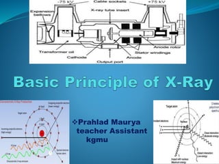
- 13. -: X-RAY TUBE :- Made of thin Pyrex glass or metal enclosure to withstand high heat load and minimize x-ray absorption Is gas evacuated So electrons won’t collide with the air molecules in the tube The X-Ray tube is the single most important component of the radiographic system. It is the part that produces the X- rays
- 15. X-ray tube construction :-
- 16. X-ray tube construction May have two filaments for a large and small focal spot When heated, boils off electrons Made of Thoriated Tungsten High thermionic emission High melting point (3410OC for those fact lovers) Not likely to burn out like a light bulb Thorium enhances thermionic emission and prolongs tube life Electron Sources (Cathode) X-Ray filament
- 17. Protective housing :- Made of lead & steel When x-rays are produced, they are emitted isotropically, Equal intensity in all directions We only use x-rays emitted through the window or port Called the useful or primary beam
- 19. Protective housing :- X-rays that escape through the protective housing are leakage radiation Provides mechanical support for the tube and protects from rough handling Some tubes contain oil that serves as an insulator against electric shock and as a thermal cushion Dissipate heat Some protective housing has cooling fan to air- cool the tube and oil
- 20. Internal components Cathode Discovery of cathode rays by Sir Willium Crooke The negative side of the tube and has two primary parts a filament and focusing cup Filament = a coil of wire about 2mm in diameter and 1 or 2 cm long.
- 21. Cathode :- Filament Dual-filament Focusing cup Negatively charged
- 22. Tungsten :- Filaments are usually made of tungsten Tungsten provides higher thermionic emission than other metals Tungsten has a very high melting point Suitable mechanical properties for construction purpose Allso known as Diamond of x-ray
- 23. Filament :- When current (mA) is applied to the coil of wire electron are ejected the outer-shell electrons of the filament atom are “boiled off”. This is known as Thermionic Emission or Edison Effect.
- 24. Focusing cup :- The filament is embedded in a metal cup that has a negative charge Boiled off e- tend to spread out due to electrostatic repulsion. The focusing cup confines the e- cloud to a small area
- 26. Filament Current :- When the x-ray imaging system is first turned on, a low current passes through the filament to warm it and prepare it for the thermal jolt necessary for x-ray production The current is not enough to energize the tube, just warm the wire of the filament
- 27. Space-charge effect :- The cloud of e- = space charge As the space charge becomes more negative by the boiling off of more electrons it makes it difficult for more e- to be emitted Electrostatic repulsion Space-charge effect Space-charge limiting at low kVp & high mA
- 29. Dual-focus tubes :- Most diagnostic tubes have two focal spots; large & small Large is used when large body parts are imaged Small is used when better spatial resolution is desired – better detail Filament size
- 31. Anode :- Anode is the positive side of the x-ray tube The anode conducts electricity, radiates heat and contains the target, Diameter 7.5 - 12.5 cm Two types of anodes Stationary & Rotating
- 32. Stationary Anode :- Used for dental x-rays, some portable imaging Target is button of tungsten set in block of copper Used when high tube current and power are not required because they are not capable of producing high-intensity x-ray beams in a short time
- 35. Rotating Anode :- Tungsten mixed with 5-6% rhenium, molybdenum is used as the base material Is powered by an induction motor The stator is on the outside of the glass, consist of a series of electromagnets The rotor is a shaft made of bars of copper and soft iron built into one mass
- 38. Rotating Anode
- 39. Reason for choosing tungsten as filament :- It is capable of stable electron emission at high temperature. It has high melting point. It has mechanical strength, long life, and can be easily drawn out into a fine filament. The remnant gas atom can be removed with relative ease.
- 40. Electromagnetic Induction Motor :- Anode speed 3,000-9000 rpm (revolutions per minute) The anode is driven by an electromagnetic induction motor. The induction motor consists of two principle art 1. Stator 2. Rotor Anode Cooling Chart Heat Units (HU)
- 42. Electromagnetic induction :- As current is applied to the stator sequentially so the magnetic field rotates on the axis of the stator This magnetic field interacts with the metal (ferromagnetic rotor) causing it to rotate in unison with the magnetic field of the stator
- 43. Dead-man switch :- Rotor/Prep – applies current (mA) to the tube Allows rotor to accelerate to its designed RPM. Rotor stops about 1 min after exposure Filament current is increased to create e- cloud Exposure – applies voltage (kV) to make exposure
- 44. Focal spot :- The area of the anode’s target where x-rays are emitted The smaller the focal spot the better the resolution of the resultant image Unfortunately, as the size of the focal spot decreases, the heat of the target is concentrated into a smaller area This is the limiting factor to focal spot size
- 46. Line-focus principle :- By angling the target, the effective area of the target is much smaller than the actual area of electron interaction Effective Focal Spot The anode angle q determines the effective focal spot size: The angle q also determines the X-ray field size coverage. For small angles the X-ray field extension is limited due to absorption and attenuation effects of X-ray photons parallel to the anode surface. effective focal length = focal length • sinq
- 48. Target angle :- The smaller the target angle the smaller the effective focal spot The inclination of target face is usually 17 degrees Angles from 5 degrees to 20degrees Biangular targets are available that produce two focal spot sizes
- 49. Anode Heel Effect :- Because of the use of line-focus principle the consequence is that the radiation intensity on the cathode side of the x-ray field is higher than that on the anode side Because the e- on the anode side must travel further than the e- that are close to the cathode side of the target, the anode side x-rays have slightly lower energy than the cathode side x-rays
- 50. The smaller the anode angle, the larger the heel affect Better use anode heal effect for AP view of thoracic spine x-ray Anode Heel Effect :-
- 51. Extra focal Radiation :- X-ray tubes are designed so that the projectile e- interacts with the target. However, some of the e- bounce off the target and land on other areas This caused x-rays to be produced out side the focal spot These rays can also be called off-focus radiation Extra focal radiation is undesirable because it extends the size of the focal spot, increases patient skin dose & reduces image contrast
- 53. Fixed diaphragm in the tube housing :- Using a grid does not reduce extra focal radiation
- 55. The Control Console :- The control console is device that allows the technologist to set technical factors (mAs & kVp) and to make an exposure. Only a legally licensed individual is authorized to energize the console.
- 56. kVp = Energy mAs = Amount
- 57. Kilovoltage Peak :- kVp kVp= controls contrast (differences from black to white) One kilovolt is = to 1000 volts The amount of voltage selected for the x-ray tube Range 45 to 120 kVp (diagnostic range) kVp controls contrast Determine the energy of electron Higher kVp then higher energy of x-ray kVp is direct proportional of velocity of electron 220Volts incoming – up to 120,000 volts (120kVp) to anode side of x-ray tube
- 58. Milliampere :- mAs One milliampere is equal to one thousandth of an ampere. The amount of current supplied to the x-ray tube Range 10 to 1200 mA Time :- In seconds How long x-rays will be produced 0.001 to 6 seconds
- 59. Milliampere seconds :- mAs mAs – density (Amount of black on the film) Greater mAs, more then electron produce mAs is direct proportional of current Voltage current is reduced to milliamps to the filament (cathode) side of the tube. mA X s = mAs
- 60. How do x-rays passing through the body create an image? X-rays that pass through the body render the image dark (black) X-rays that are totally blocked render the image light (white) Air = low atomic # = x-rays get through = image is dark (black) Metal = high atomic # = x-rays blocked = image is light (white)
- 61. 5 Basic Radiographic Densities Air Fat Soft tissue/fluid Mineral Metal
- 62. Radiographic Analysis Any structure, normal or pathologic, should be analyzed for: 1. Size 2. Shape and contour 3. Position 4. Density (You must know the 5 basic densities)
- 64. Operating Console All consoles have the same basic controls: On/Off Switch Kilovoltage control Milliampere control Length of exposure/timer Focal Spot Size Automatic Exposure Control Selection of appropriate chamber Density Controls These are examples of manual exposure controls. Anything not performed with AEC is considered a manual exposure. Your distal extremities are manual exposure!
- 65. Manual Control
- 66. Automatic Exposure Control (AEC) Automatic Exposure Control is an automatic time that detects the amount of radiation passing through the patient and terminates the exposure after a appropriate amount of time Minimum reaction (response) time is determined by the length of time necessary to for the AEC to respond to the radiation and for the generator to terminate the exposure. Backup time is set at 150% (1.5 times) that of the anticipated manual exposure. If exposure is expected to be 75 kV at 100 mAs, it will terminate at 150 mAs. Most common and popular AEC device is the three chambers:
- 67. ***Remember the selection of an incorrect chamber can cause an over or underexposed image!!!
- 68. THANK YOU The goal of the education is the advancement of knowledge and the dissemination of truth.