SlideShare a Scribd company logo
1 of 14
Download to read offline
Patents by Nityanand Gopalika


Pub. No.: US 2010/0140485 A1
Pub. Date: Jun. 10, 2010
IMAGING SYSTEM AND METHOD WITH SCATTER CORRECTION


Pub. No.: US 2009/0086911 A1
Pub. Date: Apr. 2, 2009
INSPECTION TOOL FOR RADIOGRAPHIC SYSTEMS


Patent No.: US 7,480,363 B2
Date of Patent: Jan.20,2009
CONVERTING A DIGITAL RADIOGRAPH TO AN ABSOLUTE THICKNESS MAP


                       Nityanand Gopalika
111111       1111111111111111111111111111111111111111111111111111111111111111111111111111
                                                                              US 20100140485Al
(19) United States
c12) Patent Application Publication                                    (10)   Pub. No.: US 2010/0140485 A1
       Mishra et al.                                                   (43)   Pub. Date:      Jun. 10, 2010

(54)    IMAGING SYSTEM AND METHOD WITH                          (73)    Assignee:           GENERAL ELECTRIC
        SCATTER CORRECTION                                                                  COMPANY, SCHENECTADY, NY
                                                                                            (US)
                                                                (21)    Appl. No.:          12/331,549
(75)    Inventors:     Debasish Mishra, Bangalore (IN);
                       William Robert Ross, Rotterdam,          (22)    Filed:              Dec. 10,2008
                       NY (US); Thomas James                                        Publication Classification
                       Batzinger, Burnt Hills, NY (US);
                       Manoharan Venugopal, Bangalore           (51)    Int. Cl.
                       (IN); Forrest Frank Hopkins,                     G21K 1102                       (2006.01)
                       Cohoes, NY (US); Nityanand               (52)    U.S. Cl. ...................................... 250/363.1; 378/154
                       Gopalika, State College, PA (US);        (57)                        ABSTRACT
                       Vamshi Krishna Reddy
                       Kommareddy, Bangalore (IN);              An imaging technique is provided for acquiring scatter free
                       Rajashekar Venkatachalam,                images of an object. The technique includes acquiring a plu-
                       Bangalore (IN); Prasad Thapa,            rality of projection images of the object using a source and a
                       Bangalore (IN)                           detector oriented at a plurality of projection angles relative to
                                                                the object, and generating a plurality of scatter free projection
                                                                images by correcting the plurality of projection images based
        Correspondence Address:                                 on respective ones of a plurality of stored scatter images. The
        GENERAL ELECTRIC COMPANY                                scatter images are generated and stored for each of the pro-
        GLOBAL RESEARCH                                         jection angles by positioning a scatter rejection plate between
        ONE RESEARCH CIRCLE, PATENT DOCKET                      the object and the detector. The technique further includes
        RM. BLDG. K1-4A59                                       reconstructing a three-dimensional image of the object based
        NISKAYUNA, NY 12309 (US)                                on the scatter free projection images.


                                                                                                                             ~66


70
                                                                                              VCT system              80


         Interpolation to generate full scatter image      76


                                                                                       bad pixel correction                   6
                       78     Compute scatter image
                              for each angle and store.

                                                                                            Reconstruction              88
Patent Application Publication     Jun. 10, 2010 Sheet 1 of 6       US 2010/0140485 A1


                                                                             ~10


      RADIATION                    MOTOR                           DATA
     CONTROLLER                  CONTROLLER                     ACQUISITION
                                                           (     CIRCUITRY
     30J                    28J                       32/'-----r------1


             I                   PROCESSOR
                                                                        I

    I   MEMORY                                                  I PRINTER~
                       36
                                                                              42
                                   OPERATOR           38
        I   DISPLAY 1~-+------tWORKSTATION         ,.--J


            405


                                         FIG.1
Patent Application Publication            Jun. 10, 2010 Sheet 2 of 6                    US 2010/0140485 A1

                                                                                 ~10


                                                                        /46
                 ~--------------------------------~~

                 .. .........                   ...... .
                                                . .....
                 . . . . . .. . . . .
                     ......
                                                                        ..
                 .............
                       ........                 . ..... .          00: ~~50
                 . ...........
                   . . . ..                     . ..... .
                 .
                 ............                                           0
                                                                                "--48
                                                . ............ .
                                                                            :


                 . . . . .. . .. . .
                 ......                         . ......
                                                .....
                 . . . . . .. . . . . .         . . . . ..
                                                ......
                 .......
                                                               ·.
                 . . . . . .. .
                            .                   . ..... . . . . . . .
                                                .... .
                 ............
                 .. ....                        ..... . ....... .
                                          FIG. 2
                                                                                 ~44


                                                                        /52
                 r---------------------------------~~


                                                                                "-so


                                        FIG. 3
Patent Application Publication                                                                                                         Jun. 10, 2010 Sheet 3 of 6                                                                                   US 2010/0140485 A1


    0                                                                                                                                                   0
    <0                                                                                                                                                  <0

                                         -.-·.                                                                                                                       .~.:
                                                                                                                                                                                             -~·   +

                                                                                                                                                                                                           .·.:
                                                                                                                                                                                                                                       -~      .

                                                                                                                                                              ~   ,.
                                                                                                                                                                                                                  . -_-   -   -~   .
                                                                                                                                                                                    -,
                                                                                                                                                                                                                  _.-
                                                                                                                                                                                                           -_;
                                                                                                                                                              . .:                   .   ~     . ..              -.
                                                                                                                                                                                         .   ·· .-
                                                                                                                                                                                         ... ·:

                                                                                                                                                                                                                      .··--
                                                                                                                                                                                                                               ._~     :   .
                                                                                                                                                                                                           .:·-         _.-
                                                                                                                                                                                     - ·.. -·          ~                  .    ·.·     ~··     .
                                                                                                                                                                              -·:
                                                                                                                                                                  '    ·.'     ~    :-


                                                                                  II                                                                                                                                                               II

    «>                                                                                                                                                  «>
    1.0                                                                                                                                                 1.0

         ..................................
          e e ••          I   I   I   I   I


          ................................. .
          I   I   I   I   I   I   I   I   I


          .................................
                                              I
                                              I
                                                  I
                                                  I
                                                      I
                                                      I
                                                          I
                                                          I
                                                              I
                                                              I
                                                                  I
                                                                  I
                                                                      I
                                                                      I
                                                                          I
                                                                          I
                                                                              I
                                                                              I
                                                                                   I
                                                                                   I
                                                                                       I
                                                                                       I
                                                                                           I
                                                                                           I
                                                                                               I
                                                                                               I
                                                                                                   I
                                                                                                   I
                                                                                                       I
                                                                                                       I
                                                                                                               I
                                                                                                               I
                                                                                                                   I
                                                                                                                   I
                                                                                                                       I
                                                                                                                       I
                                                                                                                           I
                                                                                                                           I
                                                                                                                               I
                                                                                                                               I
                                                                                                                                   I
                                                                                                                                   I
                                                                                                                                       I
                                                                                                                                       I
                                                                                                                                           I
                                                                                                                                           I
                                                                                                                                               I
                                                                                                                                               I
                                                                                                                                                   '


          ....................... .
          :::::::::::::::::::::::.
          ....................... .··~~~~~
          ......................... .
          •   •   •   •   •   •   •   •   •   •   •   •   •   •   •   •   •   •    •   •   •   •   •           •       0


          .... ..................
          ........................
          •   •   •   .. •    •   •   •   •   •   •   •   •   •   •   •   •   •    •   •   •   •   •       0


          ..... .................. .
          •

          I
              •

              I
                  •

                  I
                      •

                      I
                          •

                          I
                              •

                              I
                                  •

                                  I
                                      •

                                      I
                                          •

                                          I
                                              •

                                              I
                                                  •

                                                  I
                                                      •

                                                      I
                                                          •

                                                          I
                                                              •

                                                              I
                                                                  •

                                                                  I
                                                                      •

                                                                      I


          : : : : : : : : : : : : : : : : : : : : : : ;1'5..::'.-~~~"';.
                                                                          •

                                                                          I
                                                                              •

                                                                              I
                                                                                   •

                                                                                   I
                                                                                       •

                                                                                       I
                                                                                           •

                                                                                           I" I
                                                                                               •   •

                                                                                                   I
                                                                                                           0       •


          I   I   I   I. I        I   I   I   I   I   I   e   I   e   I   I   I    e e     I" I    I           '


          .................................. .
          ........................... ................. .
          ..... .. . .... .... ..
          ................ ....... ..........
          ...................................
                          ... .           . .....

    <0                                                                                                                                                  <0
    1.0                                                                                                                                                 1.0


                                                                                                                                                       (.9
                                                                                                                                                       LL
Patent Application Publication   Jun. 10, 2010 Sheet 4 of 6   US 2010/0140485 A1


                                                                 L{)
'"=
                                                                                                             ~
                                                                                                             .....
                                                                                                       ~66
                                                                                                             ('D

                                                                                                             =
                                                                                                             .....
                                                                                                             ~
                                                                                                             -
                                                                                                             ....
                                                                                                             'e
                                                                                                             (')

                                                                                                             ....
                                                                                                             ~
                                                                                                             .....
                                                                                                             0
70                                                                                                           =
                                                                                                             '"=
                                                    8                       VCT system     1 .._80          =
                                                                                                             -
                                                                                                             ....
                                                                                                             0"
                                                                                                             (')

                                                                                                             ....
                                                                                                             ~
                                                                                                             .....
                                                                                                             0
              Scatter grid image      72                                                                     =
                                                                        Raw data acquisition     1 '-82
                                                                                                             2'
                                                                                                             :=
             Centroid detection        74                                                                    ....
                                                                                                             ~0
                                                                                                             N
                                                             •    C>l   Subtract scatter image         84    ....
                                                                                                             0
                                                                                                             0

     Interpolation to generate full scatter image                                                            rFJ
                                                        76                                                   =-
                                                                                                             ('D

                                                                                                             .....
                                                                                                             ('D

                                                                                                             Ul
                                                                                                             0
                                                                        Normalization and                    .....
                                                                                                             0
                                                                        bad pixel correction           86
                   78     Compute scatter image
                          for each angle and store.                                                          c
                                                                                                             rFJ
                                                                                                             N
                                                                                                             ....
                                                                                                             0
                                                                                                             ..._
                                                                                                             0
                                                                                                  88
                                                                                                             ....
                                                                                                             0
                                                                                                             .j;o.
                                                                                                             0
                                                                                                             .j;o.
                                                                                                             QO
                                                                                                             Ul

                                                         FIG. 6                                              >
                                                                                                             ....
Patent Application Publication   Jun. 10, 2010 Sheet 6 of 6   US 2010/0140485 A1


                                                                 _.-90


                                                                 _.-92


        FIG. 7


                                                                 _.-94
US 2010/0140485 AI                                                                                                 Jun. 10,2010
                                                                   1


      IMAGING SYSTEM AND METHOD WITH                                   [0005] As manufacturing tolerances become tighter, there
            SCATTER CORRECTION                                         is a corresponding increase in the demands for metrology
                                                                       techniques for maintaining the tolerances. The need for qual-
                      BACKGROUND                                       ity and performance testing has become an integral part of the
                                                                       production or manufacturing process. Thus, in order to
[0001] The invention relates generally to the field of non-            improve CT inspection accuracy and efficiency, more effec-
invasive imaging and more specifically to the field of com-            tive methods are needed for removing scatter radiation related
puted tomography (CT) imaging and inspection systems. In               artifacts. Accordingly, a need exists for a measurement tech-
particular, the invention relates to a technique for correcting        nique that is relatively inexpensive, versatile and program-
scatter from digital radiographs acquired via volumetric com-          mable for different applications and that requires low main-
puted tomography (VCT) systems.                                        tenance.
[0002] Inspection of objects is of vital importance in manu-           [0006] It is therefore desirable to provide an improved scat-
facturing and repair industries. Various types of inspection           ter measurement and correction technique that accurately
systems, such as computed tomography (CT), coordinate                  measures scatter radiation in the projection images and
measuring machines (CMM), laser-based profilometry, light              removes the same from the projection images, thereby
gauge, infrared and others, are used in industrial inspection          improving the VCT image quality. It is also desirable that the
processes for a wide variety of applications. For example,             improved scatter measurement and correction technique is
these inspection systems may be used for measuring dimen-              inexpensive and computationally efficient and time efficient,
sions or for identifying defects in manufactured parts, such as        thereby increasing the throughput of the VCT system.
turbine blades. Each of these inspection systems has its
advantages and disadvantages. Modalities such as CMM and                                  BRIEF DESCRIPTION
laser-based profilometry typically measure external surfaces           [0007] Briefly, in accordance with one aspect of the present
with high accuracy, but cannot measure internal features               invention, a method is provided for imaging an object. The
unless the object is cut open. To date, CT is the most versatile       method provides for acquiring a first projection image of the
of the measurement/inspection systems for revealing both the           object using a source and a detector. The first projection
internal and external structures of industrial parts in a non-         image includes a primary image of the object and a scatter
destructive manner. Because of their ability to provide inter-         image of the object. The method also provides for positioning
nal as well as external measurements, CT based techniques              a scatter rejection plate between the object and the detector,
may facilitate processes such as reverse engineering, rapid            and acquiring a second projection image of the object with the
prototyping, casting simulation and validation, tire develop-          scatter rejection plate disposed between the object and the
ment, first article inspection, ceramic porosity inspection,           detector. The second projection image includes the primary
process validation, parts qualification and defect detection,          image of the object. The method further provides for gener-
among others. However, CT based techniques may also have               ating a scatter image of the object based on the first projection
certain limitations, which may deter their widespread use.             image and the second projection image, and storing the scat-
[0003] For example, volumetric computerized tomography                 ter image of the object for subsequent imaging. Systems and
(VCT) imaging for industrial applications (e.g., imaging of            computer programs that afford such functionality may be
metallic parts) typically provides unsatisfactory images hav-          provided by the present invention.
ing image artifacts due to radiation-matter interaction based          [0008] In accordance with another aspect of the present
artifacts, scanner based artifacts, reconstruction techniques          invention, a method is provided for imaging an object. The
based artifacts, and so forth. The radiation-matter interaction        method provides for acquiring a plurality of projection
based artifacts may further include beam hardening artifacts           images of the object using a source and a detector oriented at
and artifacts due to x-ray scatter radiations. Scatter radiation       a plurality of projection angles relative to the object, and
in the projection images reduces the contrast of the projection        generating a plurality of scatter free projection images by
images, produces degradation of or blurs sharp features of the         correcting the plurality of projection images based on respec-
object in the generated volume images, and reduces the accu-           tive ones of a plurality of stored scatter images. The scatter
racy of metrology applications and the detectability of                images are generated and stored for each of the projection
smaller features. Scatter radiation is a strong function of the        angles by positioning a scatter rejection plate between the
imaging parameters such as the object under imaging, beam              object and the detector. The method further provides for
spectrum used, geometrical distances, and the surrounding              reconstructing a three-dimensional image of the object based
medium. Due to various dependencies in the imaging param-              on the scatter free projection images. Here again, systems and
eters, an accurate estimation of the scatter signal content in         computer programs affording such functionality may be pro-
projection imaging is challenging. Physics-based models are            vided by the present invention.
often used for predicting scatter content in x-ray images,             [0009] In accordance with an additional aspect of the
however they are time consuming and predict only scatter               present invention, a volumetric CT system is provided for
arising out of the object under scanning, provided the material        imaging an object. The volumetric CT system includes a
properties are known.                                                  source and a detector configured to move with respect to the
[0004] There exist different techniques for scatter measure-           object. The detector is further configured to acquire a plural-
ment and scatter correction in acquired projection images.             ity of projection images of the object from a plurality of
For example, one popular scatter measurement technique                 projection angles. The volumetric CT system further includes
employs a beam stopper located between the radiation source            a processor configured to generate a plurality of scatter free
and the object being scanned in a VCT system to measure the            projection images by correcting the projection images based
scatter at a corresponding location. However, most currently           on respective stored scatter images, and to reconstruct a three-
known techniques primarily address the object scatter and              dimensional image of the object based on the scatter free
involve time-consuming computer simulations.                           projection images. The scatter images are generated and
US 2010/0140485 AI                                                                                                Jun. 10,2010
                                                                  2


stored for each of the projection angles by employing a scatter       positioned. Non-limiting examples of the object 12 include
rejection plate positioned between the object and the detector.       industrial parts, including but not limited to turbine airfoils,
                                                                      blades, disks, and shafts. It should be noted that a particular
                        DRAWINGS                                      region of the object 18 may be chosen by an operator for
                                                                      imaging so that the most useful scan of the region may be
[001 0] These and other features, aspects, and advantages of          acquired.
the present invention will become better understood when the
                                                                      [0020] A portion of the radiation 20 passes through or
following detailed description is read with reference to the
                                                                      around the object 18 and impacts the detector array 16. The
accompanying drawings in which like characters represent
                                                                      detector array 16 may be an area detector and is generally
like parts throughout the drawings, wherein:
                                                                      formed as a two-dimensional array of detection elements. In
[0011] FIG. 1 depicts an exemplary flat panel VCT system
                                                                      one implementation, the detector array 16 may be a flat-panel
for imaging an object in which aspects of the present tech-
                                                                      detector formed as rows and colunms of detector elements
nique may be practiced;
                                                                      that may be individually read out. Each detector element
[0012] FIGS. 2 and 3 depicts scatter rejection plates in
                                                                      produces an electrical signal that represents the intensity of
accordance with aspects of the present technique for use in
                                                                      the incident radiation 20 at the detector element when the
flat panel VCT system of FIG. 1;
                                                                      radiation 20 strikes the detector array 16. Typically, signals
[0013] FIG. 4 depicts a schematic for generating a scatter
                                                                      are acquired at one or more view angle positions around the
grid image by employing the scatter rejection plates of FIGS.
                                                                      object 18 so that a plurality of radiographic views may be
2 and 3 in accordance with aspects of the present technique;
                                                                      collected. These signals are acquired and processed to recon-
[0014] FIG. 5 depicts a schematic for interpolating the scat-         struct an image of the features internal as well as external to
ter grid image obtained by the technique ofFIG. 4 to generate         the object 18.
a complete scatter image in accordance with aspects of the
                                                                      [0021] The object 18, the radiation source 12, and the
present technique;
                                                                      detector array 16 are typically displaced relative to each other,
[0015] FIG. 6 depicts a control logic for inspecting an
                                                                      allowing projection data to be acquired at various views rela-
object via the flat panel VCT system of FIG. 1 by employing
                                                                      tive to the object 18 if desired. For example, in one imple-
a scatter measurement and correction technique in accor-
                                                                      mentation, the object 18 may be positioned on a table, such as
dance with aspects of the present technique; and
                                                                      a turntable, so that the object 18 may be rotated during the
[0016] FIG. 7 depicts, for a turbine fan blade, uncorrected
                                                                      examination process to expose the object 18 to the stream of
image and scatter corrected images by employing the control
                                                                      radiation 14 from all sides. Alternatively, the radiation source
logic of FIG. 6.
                                                                      12 and/or the detector array 16 may be disposed on a gantry,
                                                                      which may be rotated around the object 18 placed on a table
                DETAILED DESCRIPTION
                                                                      during the examination process. Further, in certain embodi-
[0017] The present techniques are generally directed to               ments, components of the imaging system as well as the
computed tomography (CT) imaging resulting in improved                imaged object may be moved during the examination process
image quality. Such imaging techniques may be useful in a             to acquire projection images at different views. As the object
variety of imaging contexts, such as medical imaging, indus-          18 and the radiation source 12 rotate relative to each other, the
trial metrology and inspection, security screening, baggage or        detector array 16 collects data of radiation attenuation at the
package inspection, and so forth. Moreover, such imaging              various view angles relative to the object 18.
techniques may be employed in a variety of imaging systems,           [0022] Data collected from the detector array 16 then typi-
such as CT systems, tomosynthesis systems, X-ray imaging              cally undergoes pre-processing to condition the data to rep-
systems, and so forth. Though the present discussion provides         resent the line integrals of the attenuation coefficients of the
examples in an industrial inspection context with respect to          scanned objects 18. The processed data, commonly called
CT systems resulting in improved measurement and inspec-              projections, are then reconstructed to formulate a volumetric
tion accuracy, one of ordinary skill in the art will readily          image of the scanned area, as discussed in greater detail
apprehend that the application of these techniques in other           below.
contexts and in other systems is well within the scope of the         [0023] Operation of the source 12 is controlled by a system
present techniques.                                                   controller 22, which furnishes both power, and control signals
[0018] Referring now to FIG. 1, an imaging system 10 for              for examination sequences. Moreover, the detector array 16 is
use in accordance with the present technique is illustrated. In       coupled to the system controller 22, which commands acqui-
the illustrated embodiment, the imaging system 10 is a volu-          sition of the signals generated in the detector array 16. The
metric computed tomography (VCT) system designed both to              system controller 22 may also execute various signal process-
acquire image data and to process the image data for display          ing and filtration functions, such as for initial adjustment of
and analysis in accordance with the present technique. In the         dynamic ranges, interleaving of digital image data, and so
illustrated embodiment, the imaging system 10 includes a              forth. In general, the system controller 22 commands opera-
radiation source 12, such as an X-ray source. A collimator            tion of the imaging system 10 to execute examination proto-
may be positioned adjacent to the radiation source 12 for             cols and to process acquired data. In the present context,
regulating the size and shape of a stream of radiation 14 that        system controller 22 may also include signal processing cir-
emerges from the radiation source 12.                                 cuitry and other circuitry, typically based upon a general
[0019] In typical operation, the radiation source 12 projects         purpose or application-specific digital computer, with asso-
a stream of radiation 14, such as an X-ray beam, towards a            ciated memory circuitry. The associated memory circuitry
detector array 16 placed on the opposite side of the radiation        may store programs and routines executed by the computer,
source 12, relative to the imaged object. The stream of radia-        configuration parameters, image data, and so forth. For
tion 14 passes into an imaging volume in which an object 18,          example, the associated memory circuitry may store pro-
such as a turbine blade or other item to be imaged may be             grams or routines for implementing the present technique.
US 2010/0140485 AI                                                                                                 Jun. 10,2010
                                                                  3


[0024] In the embodiment illustrated in FIG. 1, the system            [0028] The processor 34 is typically used to control the
controller 22 is coupled to a linear positioning subsystem 24         imaging system 10. The processor 34 may also be adapted to
and a rotational subsystem 26. In particular, the system con-         control features enabled by the system controller 22, i.e.,
troller 22 may include a motor controller 28 that controls the        scanning operations and data acquisition. Indeed, the system
operation of the linear positioning subsystem 24 and the              controller 22 may be implemented as hardware and software
rotational subsystem 26. The rotational subsystem 26 enables          components of the depicted processor 34. In addition, the
the X -ray source assembly and/or the detector assembly to be         processor 34 may be configured to receive commands and
rotated around the object or the patient 18. It should be noted       scanning parameters from an operator via an operator work-
that the rotational subsystem 26 may include a gantry. Thus,          station 38. For example, the operator workstation 38 may be
the system controller 22 may be utilized to control the rota-         equipped with a keyboard and/or other input devices by
tional speed and position of the gantry. Alternatively, the           which an operator may control the imaging system 10. Thus,
rotational subsystem 26 may include a motorized turntable             the operator may observe the reconstructed image and other
and the system controller 22 may be configured to rotate the          data relevant to the system from processor 34, initiate imag-
motorized turntable, thereby rotating the object 18 one or            ing and so forth. Where desired, other computers or worksta-
multiple turns during an examination. The linear positioning          tions may perform some or all of the functions of the present
subsystem 24 enables the object 18 to be displaced linearly,          technique, including post-processing of image data simply
such as by moving a table or support on which the object 18           accessed from memory device 36 or another memory device
rests. Thus, in one embodiment, the table may be linearly             at the imaging system location or remote from that location.
moved within a gantry to generate images of particular areas          [0029] A display 40 may be coupled to one of the operator
of the object 18. In another embodiment (e.g., in a tomosyn-          workstation 38 and the processor 34 and may be utilized to
thesis system), the X-ray source may be moveable using a              observe the reconstructed image and/or to control imaging.
linear positioning subsystem. The detector position may be            Additionally, the scanned image may also be printed by a
variable, but not be controlled using a positioning subsystem.        printer 42 which may be coupled to the processor 34 and/or
It should be noted that other configurations may also be used.        the operator workstation 38, either directly or over a network.
[0025] Additionally, as will be appreciated by those skilled          It should be further noted that the processor 34 and/or opera-
in the art, the radiation source 12 may be controlled by a            tor workstation 38 may be coupled to other output devices
radiation controller 30 disposed within the system controller         that may include standard or special purpose computer moni-
22. Particularly, the radiation controller 30 may be configured       tors and associated processing circuitry. Furthermore, addi-
to provide power and timing signals to the radiation source           tional operator workstations may be further linked in the
12. Further, the system controller 22 may include data acqui-         imaging system 10 for outputting system parameters,
sition circuitry 32. In this exemplary embodiment, the detec-         requesting inspection, viewing images, and so forth, so that
tor array 16 is coupled to the system controller 22, and more         more than one operator may perform operations related to the
particularly to the data acquisition circuitry 32. The data           imaging system 10. For example, one operator may utilize
acquisition circuitry 32 typically receives sampled analog            one operator workstation to image acquisition while a second
signals from the detector array 16 and converts the data to           operator utilizes a second operator workstation to reconstruct
digital signals for subsequent processing by a processor 34.          and/or review the results of the imaging routines. In general,
Such conversion, and indeed any preprocessing, may actually           displays, printers, workstations, and similar devices supplied
be performed to some degree within the detector assembly              within the imaging system 10 may be local to the data acqui-
itself.                                                               sition components, or may be remote from these components
[0026] The processor 34 is typically coupled to the system            linked to the imaging system 10 via one or more configurable
controller 24. Data collected by the data acquisition circuitry       networks, such as the Internet, virtual private networks, and
32 may be transmitted to the processor 34 for subsequent              so forth.
processing and reconstruction. Reconstruction of the image            [0030] The exemplary imaging system 10, as well as other
may be done by general or special purpose circuitry of the            imaging systems based on radiation attenuation, may employ
processor 34. Once reconstructed, the image produced by the           a variety of scatter mitigation and/or correction techniques for
imaging system 10 reveals internal as well as external fea-           improving the image quality. For example, the present tech-
tures of the object 18. Alternatively, an image reconstructor,        nique employs scatter rejection plates, depicted in FIGS. 2
that is coupled to or is a part of a processor 34, may receive        and 3 and represented generally at reference numeral 44, for
sampled and digitized data from the data acquisition circuitry        rejecting the scatter radiation resulting from object as well as
32 and may perform high-speed image reconstruction to gen-            those resulting from the background in accordance with
erate one or more images of the scanned object 18.                    aspects of the present technique.
[0027] The processor 34 may include or be in communica-               [0031] In one embodiment, the scatter rejection plate 44
tion with a memory 36. It should be understood that any type          may be an aperture plate 46, as illustrated in FIG. 2. The
of computer accessible memory device suitable for storing             aperture plate 46 includes a plurality of sub-centimeter sized
and/or processing such data and/or data processing routines           circular apertures 48 drilled in a plate 50. In certain embodi-
may be utilized by such an exemplary imaging system 10.               ments, the apertures may be about 1-2 millimeters in diameter
Moreover, the memory 36 may comprise one or more                      spaced apart at about 5 millimeters from each other (center-
memory devices, such as magnetic or optical devices, of               to-center). Alternatively, the scatter rejection plate 44 may be
similar or different types, which may be local and/or remote          a collimator plate 52, as illustrated in FIG. 3. The collimator
to the system 10. The memory 36 may store data, processing            plate 52 includes a plurality of sub-centimeter sized horizon-
parameters, and/or computer programs comprising one or                tal or vertical slots 54 drilled in a plate 50. In certain embodi-
more routines for performing the processes described herein.          ments, the slots may be about 1-2 millimeters in width spaced
Furthermore, memory 36 may be coupled directly to system              apart at about 5 millimeters from each other (center-to-cen-
controller 24 to facilitate the storage of acquired data.             ter). Typically, the plate 50 is thick and made of high-density
US 2010/0140485 AI                                                                                                  Jun. 10,2010
                                                                    4


material. The high-density material may be, for example,                interpolated based on the detected aperture points to generate
lead, tungsten or a tungsten alloy, molybdenum, tantalum or             a full or complete scatter image of the object at step 64. In
rhenium. In certain embodiments, the plate is about 10 mil-             other words, the data points are first mapped to a regular grid
limeters in thickness.                                                  and then interpolated using shape factors. As will be appre-
[0032] Further, various other scatter rejection plates may be           ciated by those skilled in the art, any type of interpolation
designed based on the specific imaging applications and                 techniques may be employed to generate the scatter image
requirements, so as to optimize scatter rejection performance.          from the scatter grid image. Non-limiting examples of the
For example, different variants of each of the two types of             interpolation techniques include bi-linear interpolation,
plates for scatter rejection (aperture plate and collimator             piecewise constant interpolation, bi -cubic interpolation, mul-
plate) may be designed. In certain embodiments, if the geom-            tivariate interpolation, and so forth.
etry of an x-ray setup is fixed, focally aligned apertures or           [0036] As will be appreciated by those skilled in the art, a
collimators may be designed. This provides that no primary              scatter image of the object is generated for each of the pro-
x-ray beam deflect at wide angles. In other words, the aper-            jection angles. The generated scatter images are stored in the
tures 48 or the slots 54 may be drilled at an angle parallel to         memory for subsequent imaging. As will be appreciated by
the angle of incidence of the X -ray beam, so as to maximize            those skilled in the art, subsequent imaging includes acquir-
the rejection of scatter radiation. Similarly, the aperture plate       ing projection images of the object from various projection
or the collimator plate may be optimized for a particular               angles and generating scatter free projection images for each
X-ray energy application. Further, it should be noted that the          projection angle based on the projection images and respec-
spacing of the apertures or collimators may be based on                 tive stored scatter images. The scatter free projection images
specific applications depending on cost and image quality               are generated by correcting the projection images based on
requirements.                                                           respective ones of stored scatter images. In certain embodi-
[0033] The flat panel VCT system 10 employs the scatter                 ments, the scatter free projection images may be corrected by
rejection plates 44 for generating initial scatter image of the         subtracting the respective pre-stored scatter images from the
object 18 in accordance with aspects of the present technique.          acquired projection image for each of the projection angle. It
For example, as illustrated in the schematic of FIG. 4, the             should be noted that the orientation of the object during
VCT system 10 acquires a first projection image 56 of the               subsequent imaging should be substantially same as it was
object 18 without the scatter rejection plate 44. This first            during generation of scatter image for each projection angles.
projection image 56 includes a primary image of the object as           The scatter free projection images may be further processed
well as a scatter image of the object. The VCT system 10 then           to normalize and correct for any bad pixels in the scatter free
acquires a second projection image 58 of the object with the            projection images. The generated or processed scattered free
scatter rejection plate 44 positioned between the object 18             projection images may then be reconstructed to generate a
and the detector 16. This second projection image 58 includes           three-dimensional image of the object. As will be appreciated
only the primary image of the object 18. As will be appreci-            by those skilled in the art, any suitable reconstruction tech-
ated by those skilled in the art, the primary image is free from        nique may be employed for the image reconstruction. Non-
any artifacts caused due to scatter radiation. Further, it should       limiting examples of the reconstruction techniques include
be noted that, in the second projection image, the primary              filtered back projection (FBP), iterative filtered back projec-
image of the object 18 is formed only at certain discrete               tion (IFBP), iterative reconstruction and/or statistical recon-
locations where measurements are obtained through the aper-             struction techniques.
tures or slots and is therefore dependent on the type of scatter        [0037] The exemplary imaging system 10 may generate
rejection plate 44 employed to acquire the image. The illus-            images of the object under examination by the techniques
trated embodiment depicts the primary image acquired by                 discussed herein. In particular, as will be appreciated by those
using aperture plate 46 as well as the primary image acquired           of ordinary skill in the art, control logic and/or automated
by using collimator plate 52. The first image 56 and the                routines for performing the techniques and steps described
second projection image 58 may also be referred as non-grid             herein may be implemented by the imaging system 10 ofFIG.
image 56 and grid image 58 respectively.                                1, by hardware, software, or combinations of hardware and
[0034] The VCT system 10 then generates the scatter image               software. For example, suitable code may be accessed and
of the object at the respective one of the projection angles            executed by the processor 34 to perform some or all of the
based on the first projection image 56 and the second projec-           techniques described herein. Similarly application specific
tion image 58. In particular, the processor 34 subtracts the            integrated circuits (ASICs) configured to perform some or all
second projection image 58 from the first projection image 56           of the techniques described herein may be included in the
to generate a scatter grid image 60. It should be noted that            processor 34 and/or the system controller 22.
acquisition of the first projection image 56 and the second             [0038] For example, referring now to FIG. 6, exemplary
projection image 58, and the generation of scatter grid image           control logic for inspecting an object by employing scatter
60 are performed for each of the projection angles.                     measurement and correction technique on the imaging sys-
[0035] The generated scatter grid image 60 is then interpo-             tem such as flat panel VCT system 10 is depicted in accor-
lated to generate a complete scatter image. FIG. 5 depicts an           dance with aspects of the present technique. As illustrated in
example schematic for interpolating a scatter grid image                the flowchart 66, a non-grid image and a grid image may be
obtained by the technique of FIG. 4 to generate a complete              acquired for a given object at multiple projection angles via
scatter image in accordance with aspects of the present tech-           the VCT system at steps 68 and 70 respectively. As discussed
nique. As illustrated, all aperture points or centroids for the         above, the grid image may be acquired by employing the
scatter grid image are first detected at step 62. It should be          scatter rejection plate positioned between the object and the
noted that, for the scatter grid image acquired by employing a          detector. A scatter grid image is then generated based on the
collimator plate, the aperture points may be detected based on          non-grid image and the grid image at step 72. The scatter grid
the required pixel resolution. The scatter grid image is then           image is then processed to detect multiple aperture points or
US 2010/0140485 AI                                                                                                   Jun. 10,2010
                                                                     5


centeroids at step 74. Based on the detected centeroids, the             orientation, and x-ray technique prior to a VCT scan and use
scatter grid image is then interpolated to generate a full scatter       it during an actual imaging scan. This improves the through-
image of the given object at step 76. The process is repeated            put of the VCT system since scatter correction for the projec-
for each of the multiple projection angles and the generated             tion images is then a simple image subtraction process. Fur-
scatter images for the respective projection angles are stored           ther, as will be appreciated by those skilled in the art, it is
for subsequent imaging applications at step 78.                          easier to measure primary radiation than the scatter radiation
[0039] During subsequent imaging, the VCT system                         and positioning the scatter rejection plate between the object
images the object at step 80 and acquires projection images of           and the detector makes the measurement of primary radiation
the object from various projection angles at step 82. It should          substantially convenient. Additionally, the use of narrow col-
be noted that, the projection images are acquired for same               limators permits the imaging of the higher spatial frequency
projection angles for which the scatter images have been                 content of the scatter images. Moreover, the technique per-
generated. The scatter free projection images are then gener-            mits capture and correction of the beam scatter (scatter due to
ated based on the projection images and corresponding scat-              the imaged object) as well as the background radiation scatter
ter images at step 84. In one embodiment this is done by                 (scatter due to external object).
subtracting the corresponding scatter images from the                    [0043] Further, as will be appreciated by those skilled in the
acquired projection images. The scatter free projection                  art, the technique may be employed as a part of the system
images are then post processed at step 86. The post processing           calibration process prior to the actual imaging application.
may involve normalization and correction for bad pixels. The             Typically, prior to performing VCT imaging for metrology or
processed scatter free projection images are then recon-                 inspection, an operator has to perform a few system calibra-
structed to generate a three-dimensional image of the object             tion steps such as, flat field calibration of the detector, bad
at step 88.                                                              pixel test and calibration of the detector, geometrical align-
[0040] FIG. 7 illustrates, for a turbine fan blade, uncor-               ment and calibration of the system. The scatter correction
rected image and scatter corrected images by employing con-              technique described in the embodiments discussed above
trol logic of FIG. 6. Image 92 is the uncorrected image                  may similarly become a part of the calibration process where
obtained by a typical VCT system, while images 94 and 96 are             the scatter images will be obtained for a specific object and
scatter corrected images obtained by employing the scatter               stored prior to the performance of an actual metrology or
rejection plate and the control logic described via the flow-            inspection process.
chart 66. Further, it should be noted that image 94 is the               [0044] While only certain features of the invention have
scatter corrected image obtained by employing aperture plate,            been illustrated and described herein, many modifications
while image 96 is the scatter corrected image obtained by                and changes will occur to those skilled in the art. It is, there-
employing collimator plate.                                              fore, to be understood that the appended claims are intended
[0041] It should be noted that one or more imaging param-                to cover all such modifications and changes as fall within the
eters should be substantially maintained (that is, maintained            true spirit of the invention.
at substantially similar values) for a particular imaging appli-
cation and inspection requirement. Non-limiting examples of
the imaging parameters include a type of object being                       1. A method for imaging an object, the method comprising:
imaged, a shape and an orientation of the object being                      acquiring a first projection image of the object using a
imaged, projection angles from which the scatter images and                    source and a detector, the first projection image com-
subsequent projection images are acquired, an x-ray tech-                      prising a primary image of the object and a scatter image
nique being employed, a geometry and one or more settings                      of the object;
of the source and the detector, distance of the scatter rejection           positioning a scatter rejection plate between the object and
plates from the source and the detector, and so forth. For                     the detector;
example, the above process may be set for imaging similar                   acquiring a second projection image of the object with the
objects (e.g., turbine blades). The objects should be mounted                  scatter rejection plate disposed between the object and
on the turntable at substantially similar orientations. Further,               the detector, the second projection image comprising the
the distance of the scatter rejection plate from the source and                primary image of the object;
the detector should be substantially maintained while acquir-               generating a scatter image of the object based on the first
ing and storing the scatter images for each of the predeter-                   projection image and the second projection image; and
mined projection angles. In one embodiment, this may be
                                                                            storing the scatter image of the object for subsequent imag-
achieved by coupling or attaching the scatter rejection plate to
                                                                               ing.
the two-dimensional flat panel detector array. Additionally,
projection images should be acquired for projection angles                  2. The method of claim 1, wherein generating the scatter
for which the scatter images have been generated and stored.             image further comprises generating a scatter grid image by
Moreover, the x-ray technique employed, the geometry and                 subtracting the second projection image from the first projec-
other settings for the source and the detector should be main-           tion image.
tained at substantially similar values, such that the beam                  3. The method of claim 2, wherein generating the scatter
shape and intensity are same for various image acquisitions.             image further comprises detecting a plurality of aperture
[0042] As will be appreciated by those skilled in the art, the           points for the scatter grid image and interpolating the scatter
scatter correction techniques described in the various                   grid image based on the aperture points.
embodiments discussed above permit a measurement of the                     4. The method of claim 1, wherein the scatter image is
scatter content in the projection images used for VCT imag-              stored for each of a plurality of projection angles.
ing and correct the projection images, thereby improving the                5. The method of claim 1, wherein subsequent imaging
VCT image quality. The technique permits measurement of                  comprises acquiring a plurality of projection images of the
scatter content in x-ray images for a given geometry, scanning           object from a plurality of projection angles.
US 2010/0140485 AI                                                                                                 Jun. 10,2010
                                                                   6


   6. The method of claim 5, wherein subsequent imaging                   16. The method of claim 15, wherein generating the scatter
comprises generating a plurality of scatter free projection            images for each of the respective projection angles com-
images based on the projection images and respective scatter           prises:
images.                                                                   acquiring a first projection image of the object, the first
   7. The method of claim 6, wherein subsequent imaging                      projection image comprising a primary image of the
comprises reconstructing a three-dimensional image of the                    object and the scatter image of the object;
object based on the scatter free projection images.                       positioning the scatter rejection plate between the object
                                                                             and the detector;
   8. The method of claim 7, wherein reconstructing com-
                                                                          acquiring a second projection image of the object with the
prises normalizing and correcting at least one bad pixel in a                scatter rejection plate disposed between the object and
plurality of scatter free projection images.                                 the detector, the second projection image comprising the
   9. The method of claim 1, further comprising maintaining                  primary image of the object; and
a plurality of substantially similar imaging parameters.                  generating the scatter image of the object based on the first
   10. The method of claim 9, wherein the imaging param-                     projection image and the second projection image.
eters are selected from the group consisting of a type of object          17. The method of claim 15, wherein correcting the pro-
being imaged, a shape and an orientation of the object being           jection images comprises subtracting the scatter images from
imaged, projection angles from which the scatter images and            the respective projection images.
subsequent projection images are acquired, an x-ray tech-                 18. A volumetric CT system for imaging an object, the
nique being employed, a geometry and one or more settings              system comprising:
of the source and the detector, and combinations thereof.                 a source and a detector configured to move with respect to
                                                                             the object, wherein the detector is further configured to
   11. The method of claim 1, wherein the scatter rejection
                                                                             acquire a plurality of projection images of the object
plate is designed based on a type of imaging application so as               from a plurality of projection angles; and
to optimize scatter rejection performance.                                a processor configured to generate a plurality of scatter free
   12. The method of claim 1, wherein the scatter rejection                  projection images by correcting the projection images
plate comprises at least one of an aperture plate or a collima-              based on respective stored scatter images and to recon-
tor plate.                                                                   struct a three-dimensional image of the object based on
   13. The method of claim 12, wherein the aperture plate                    the scatter free projection images, wherein the scatter
comprises a high density material and defines a plurality of                 images are generated and stored for each of the projec-
sub-centimeter sized circular apertures.                                     tion angles by employing a scatter rejection plate posi-
   14. The method of claim 12, wherein the collimator plate                  tioned between the object and the detector.
comprises a high density material and defines a plurality of              19. The system of claim 18, wherein for each of the pro-
sub-centimeter sized horizontal or vertical slots.                     jection angles, the detector is further configured to acquire a
                                                                       first projection image of the object and a second projection
   15. A method for imaging an object, the method compris-
                                                                       image of the object with the scatter rejection plate positioned
ing:
                                                                       between the object and the detector, and wherein the proces-
   acquiring a plurality of projection images of the object            sor is further configured to generate the scatter image of the
      using a source and a detector oriented at a plurality of         object at the respective one of the projection angles based on
      projection angles relative to the object;                        the first projection image and the second projection image.
   generating a plurality of scatter free projection images by            20. The system of claim 18, wherein the scatter rejection
      correcting the plurality of projection images based on           plate is designed based on a type of imaging application so as
      respective ones of a plurality of stored scatter images,         to optimize scatter rejection performance.
      wherein the scatter images are generated and stored for             21. The system of claim 18, wherein the scatter rejection
      each of the projection angles by positioning a scatter           plate comprises at least one of an aperture plate or a collima-
      rejection plate between the object and the detector; and         tor plate.
   reconstructing a three-dimensional image of the object
      based on the scatter free projection images.                                            * * * * *

More Related Content

Similar to Nityanand gopalika Patent3

Multiscale Anomaly Detection and Image Registration Algorithms for Airborne L...
Multiscale Anomaly Detection and Image Registration Algorithms for Airborne L...Multiscale Anomaly Detection and Image Registration Algorithms for Airborne L...
Multiscale Anomaly Detection and Image Registration Algorithms for Airborne L...Jeff Barnes
 
A novel Lab-on-Tip nanomechanical platform for single molecule DNA sequencing
A novel Lab-on-Tip nanomechanical platform for single molecule DNA sequencingA novel Lab-on-Tip nanomechanical platform for single molecule DNA sequencing
A novel Lab-on-Tip nanomechanical platform for single molecule DNA sequencingZhuo Wang
 
⭐⭐⭐⭐⭐ Device Free Indoor Localization in the 28 GHz band based on machine lea...
⭐⭐⭐⭐⭐ Device Free Indoor Localization in the 28 GHz band based on machine lea...⭐⭐⭐⭐⭐ Device Free Indoor Localization in the 28 GHz band based on machine lea...
⭐⭐⭐⭐⭐ Device Free Indoor Localization in the 28 GHz band based on machine lea...Victor Asanza
 
Waters Corp. Variable Aperture Slit System (Final)
Waters Corp. Variable Aperture Slit System (Final)Waters Corp. Variable Aperture Slit System (Final)
Waters Corp. Variable Aperture Slit System (Final)Han Shen Zhang
 
DSA DEEPAK GUPTA
DSA  DEEPAK GUPTADSA  DEEPAK GUPTA
DSA DEEPAK GUPTADEEPAK
 
102 gregory j. athas - 7378003 - thin-film magnetic recording head manufact...
102   gregory j. athas - 7378003 - thin-film magnetic recording head manufact...102   gregory j. athas - 7378003 - thin-film magnetic recording head manufact...
102 gregory j. athas - 7378003 - thin-film magnetic recording head manufact...Mello_Patent_Registry
 
Analysis & Design of CMOS MEMS Gyroscope
Analysis & Design of CMOS MEMS GyroscopeAnalysis & Design of CMOS MEMS Gyroscope
Analysis & Design of CMOS MEMS GyroscopeJames D.B. Wang, PhD
 
Characterization Studies of a CdTe Pixelated Timepix Detector for Applicatio...
Characterization Studies of a  CdTe Pixelated Timepix Detector for Applicatio...Characterization Studies of a  CdTe Pixelated Timepix Detector for Applicatio...
Characterization Studies of a CdTe Pixelated Timepix Detector for Applicatio...Costa Papadatos
 
Coiled tubing technology
Coiled tubing technologyCoiled tubing technology
Coiled tubing technologyakpp01
 
Coiled tubing technology
Coiled tubing technologyCoiled tubing technology
Coiled tubing technologyakpp01
 
Brl arpa doploc satellite detection complex
Brl arpa doploc satellite detection complexBrl arpa doploc satellite detection complex
Brl arpa doploc satellite detection complexClifford Stone
 
Optical coherence tomography
Optical coherence tomographyOptical coherence tomography
Optical coherence tomographyKartik Gupta
 
white_paper_fiber_optic_sensing_rev_1.0_march16_0
white_paper_fiber_optic_sensing_rev_1.0_march16_0white_paper_fiber_optic_sensing_rev_1.0_march16_0
white_paper_fiber_optic_sensing_rev_1.0_march16_0Jacques Miéville
 
Vibration Isolation of an Air Compressor by using Sandwich Mount Isolators
Vibration Isolation of an Air Compressor by using Sandwich Mount IsolatorsVibration Isolation of an Air Compressor by using Sandwich Mount Isolators
Vibration Isolation of an Air Compressor by using Sandwich Mount IsolatorsIRJET Journal
 
Spe 101930
Spe 101930Spe 101930
Spe 101930mfathi
 
MSc_Thesis_Wake_Dynamics_Study_of_an_H-type_Vertical_Axis_Wind_Turbine
MSc_Thesis_Wake_Dynamics_Study_of_an_H-type_Vertical_Axis_Wind_TurbineMSc_Thesis_Wake_Dynamics_Study_of_an_H-type_Vertical_Axis_Wind_Turbine
MSc_Thesis_Wake_Dynamics_Study_of_an_H-type_Vertical_Axis_Wind_TurbineChenguang He
 
RFP_2016_Zhenjie_CEN
RFP_2016_Zhenjie_CENRFP_2016_Zhenjie_CEN
RFP_2016_Zhenjie_CENZhenjie Cen
 
Investigation of repeated blasts at Aitik mine using waveform cross correlation
Investigation of repeated blasts at Aitik mine using waveform cross correlationInvestigation of repeated blasts at Aitik mine using waveform cross correlation
Investigation of repeated blasts at Aitik mine using waveform cross correlationIvan Kitov
 

Similar to Nityanand gopalika Patent3 (20)

Multiscale Anomaly Detection and Image Registration Algorithms for Airborne L...
Multiscale Anomaly Detection and Image Registration Algorithms for Airborne L...Multiscale Anomaly Detection and Image Registration Algorithms for Airborne L...
Multiscale Anomaly Detection and Image Registration Algorithms for Airborne L...
 
A novel Lab-on-Tip nanomechanical platform for single molecule DNA sequencing
A novel Lab-on-Tip nanomechanical platform for single molecule DNA sequencingA novel Lab-on-Tip nanomechanical platform for single molecule DNA sequencing
A novel Lab-on-Tip nanomechanical platform for single molecule DNA sequencing
 
Nityanand gopalika Patent 2
Nityanand gopalika Patent 2Nityanand gopalika Patent 2
Nityanand gopalika Patent 2
 
⭐⭐⭐⭐⭐ Device Free Indoor Localization in the 28 GHz band based on machine lea...
⭐⭐⭐⭐⭐ Device Free Indoor Localization in the 28 GHz band based on machine lea...⭐⭐⭐⭐⭐ Device Free Indoor Localization in the 28 GHz band based on machine lea...
⭐⭐⭐⭐⭐ Device Free Indoor Localization in the 28 GHz band based on machine lea...
 
Waters Corp. Variable Aperture Slit System (Final)
Waters Corp. Variable Aperture Slit System (Final)Waters Corp. Variable Aperture Slit System (Final)
Waters Corp. Variable Aperture Slit System (Final)
 
DSA DEEPAK GUPTA
DSA  DEEPAK GUPTADSA  DEEPAK GUPTA
DSA DEEPAK GUPTA
 
102 gregory j. athas - 7378003 - thin-film magnetic recording head manufact...
102   gregory j. athas - 7378003 - thin-film magnetic recording head manufact...102   gregory j. athas - 7378003 - thin-film magnetic recording head manufact...
102 gregory j. athas - 7378003 - thin-film magnetic recording head manufact...
 
Analysis & Design of CMOS MEMS Gyroscope
Analysis & Design of CMOS MEMS GyroscopeAnalysis & Design of CMOS MEMS Gyroscope
Analysis & Design of CMOS MEMS Gyroscope
 
Characterization Studies of a CdTe Pixelated Timepix Detector for Applicatio...
Characterization Studies of a  CdTe Pixelated Timepix Detector for Applicatio...Characterization Studies of a  CdTe Pixelated Timepix Detector for Applicatio...
Characterization Studies of a CdTe Pixelated Timepix Detector for Applicatio...
 
Coiled tubing technology
Coiled tubing technologyCoiled tubing technology
Coiled tubing technology
 
Coiled tubing technology
Coiled tubing technologyCoiled tubing technology
Coiled tubing technology
 
Brl arpa doploc satellite detection complex
Brl arpa doploc satellite detection complexBrl arpa doploc satellite detection complex
Brl arpa doploc satellite detection complex
 
Optical coherence tomography
Optical coherence tomographyOptical coherence tomography
Optical coherence tomography
 
EVM_TFM_printed
EVM_TFM_printedEVM_TFM_printed
EVM_TFM_printed
 
white_paper_fiber_optic_sensing_rev_1.0_march16_0
white_paper_fiber_optic_sensing_rev_1.0_march16_0white_paper_fiber_optic_sensing_rev_1.0_march16_0
white_paper_fiber_optic_sensing_rev_1.0_march16_0
 
Vibration Isolation of an Air Compressor by using Sandwich Mount Isolators
Vibration Isolation of an Air Compressor by using Sandwich Mount IsolatorsVibration Isolation of an Air Compressor by using Sandwich Mount Isolators
Vibration Isolation of an Air Compressor by using Sandwich Mount Isolators
 
Spe 101930
Spe 101930Spe 101930
Spe 101930
 
MSc_Thesis_Wake_Dynamics_Study_of_an_H-type_Vertical_Axis_Wind_Turbine
MSc_Thesis_Wake_Dynamics_Study_of_an_H-type_Vertical_Axis_Wind_TurbineMSc_Thesis_Wake_Dynamics_Study_of_an_H-type_Vertical_Axis_Wind_Turbine
MSc_Thesis_Wake_Dynamics_Study_of_an_H-type_Vertical_Axis_Wind_Turbine
 
RFP_2016_Zhenjie_CEN
RFP_2016_Zhenjie_CENRFP_2016_Zhenjie_CEN
RFP_2016_Zhenjie_CEN
 
Investigation of repeated blasts at Aitik mine using waveform cross correlation
Investigation of repeated blasts at Aitik mine using waveform cross correlationInvestigation of repeated blasts at Aitik mine using waveform cross correlation
Investigation of repeated blasts at Aitik mine using waveform cross correlation
 

More from Nityanand Gopalika

Nityanand gopalika digital radiography performance study
Nityanand gopalika   digital radiography performance studyNityanand gopalika   digital radiography performance study
Nityanand gopalika digital radiography performance studyNityanand Gopalika
 
Nityanand gopalika spectrum validation - nde 2003
Nityanand gopalika   spectrum validation - nde 2003Nityanand gopalika   spectrum validation - nde 2003
Nityanand gopalika spectrum validation - nde 2003Nityanand Gopalika
 
Nityanand gopalika digital detectors for industrial applications
Nityanand gopalika   digital detectors for industrial applicationsNityanand gopalika   digital detectors for industrial applications
Nityanand gopalika digital detectors for industrial applicationsNityanand Gopalika
 

More from Nityanand Gopalika (6)

Nityanand gopalika digital radiography performance study
Nityanand gopalika   digital radiography performance studyNityanand gopalika   digital radiography performance study
Nityanand gopalika digital radiography performance study
 
Nityanand gopalika spectrum validation - nde 2003
Nityanand gopalika   spectrum validation - nde 2003Nityanand gopalika   spectrum validation - nde 2003
Nityanand gopalika spectrum validation - nde 2003
 
Nityanand gopalika digital detectors for industrial applications
Nityanand gopalika   digital detectors for industrial applicationsNityanand gopalika   digital detectors for industrial applications
Nityanand gopalika digital detectors for industrial applications
 
Patents by nityanand gopalika
Patents by nityanand gopalikaPatents by nityanand gopalika
Patents by nityanand gopalika
 
Nityanand gopalika
Nityanand gopalikaNityanand gopalika
Nityanand gopalika
 
Nityanand gopalika
Nityanand gopalikaNityanand gopalika
Nityanand gopalika
 

Recently uploaded

Microsoft 365 Copilot: How to boost your productivity with AI – Part one: Ado...
Microsoft 365 Copilot: How to boost your productivity with AI – Part one: Ado...Microsoft 365 Copilot: How to boost your productivity with AI – Part one: Ado...
Microsoft 365 Copilot: How to boost your productivity with AI – Part one: Ado...Nikki Chapple
 
Bridging Between CAD & GIS: 6 Ways to Automate Your Data Integration
Bridging Between CAD & GIS:  6 Ways to Automate Your Data IntegrationBridging Between CAD & GIS:  6 Ways to Automate Your Data Integration
Bridging Between CAD & GIS: 6 Ways to Automate Your Data Integrationmarketing932765
 
The Future Roadmap for the Composable Data Stack - Wes McKinney - Data Counci...
The Future Roadmap for the Composable Data Stack - Wes McKinney - Data Counci...The Future Roadmap for the Composable Data Stack - Wes McKinney - Data Counci...
The Future Roadmap for the Composable Data Stack - Wes McKinney - Data Counci...Wes McKinney
 
Data governance with Unity Catalog Presentation
Data governance with Unity Catalog PresentationData governance with Unity Catalog Presentation
Data governance with Unity Catalog PresentationKnoldus Inc.
 
Potential of AI (Generative AI) in Business: Learnings and Insights
Potential of AI (Generative AI) in Business: Learnings and InsightsPotential of AI (Generative AI) in Business: Learnings and Insights
Potential of AI (Generative AI) in Business: Learnings and InsightsRavi Sanghani
 
Emixa Mendix Meetup 11 April 2024 about Mendix Native development
Emixa Mendix Meetup 11 April 2024 about Mendix Native developmentEmixa Mendix Meetup 11 April 2024 about Mendix Native development
Emixa Mendix Meetup 11 April 2024 about Mendix Native developmentPim van der Noll
 
A Framework for Development in the AI Age
A Framework for Development in the AI AgeA Framework for Development in the AI Age
A Framework for Development in the AI AgeCprime
 
Design pattern talk by Kaya Weers - 2024 (v2)
Design pattern talk by Kaya Weers - 2024 (v2)Design pattern talk by Kaya Weers - 2024 (v2)
Design pattern talk by Kaya Weers - 2024 (v2)Kaya Weers
 
The State of Passkeys with FIDO Alliance.pptx
The State of Passkeys with FIDO Alliance.pptxThe State of Passkeys with FIDO Alliance.pptx
The State of Passkeys with FIDO Alliance.pptxLoriGlavin3
 
TeamStation AI System Report LATAM IT Salaries 2024
TeamStation AI System Report LATAM IT Salaries 2024TeamStation AI System Report LATAM IT Salaries 2024
TeamStation AI System Report LATAM IT Salaries 2024Lonnie McRorey
 
Moving Beyond Passwords: FIDO Paris Seminar.pdf
Moving Beyond Passwords: FIDO Paris Seminar.pdfMoving Beyond Passwords: FIDO Paris Seminar.pdf
Moving Beyond Passwords: FIDO Paris Seminar.pdfLoriGlavin3
 
Zeshan Sattar- Assessing the skill requirements and industry expectations for...
Zeshan Sattar- Assessing the skill requirements and industry expectations for...Zeshan Sattar- Assessing the skill requirements and industry expectations for...
Zeshan Sattar- Assessing the skill requirements and industry expectations for...itnewsafrica
 
MuleSoft Online Meetup Group - B2B Crash Course: Release SparkNotes
MuleSoft Online Meetup Group - B2B Crash Course: Release SparkNotesMuleSoft Online Meetup Group - B2B Crash Course: Release SparkNotes
MuleSoft Online Meetup Group - B2B Crash Course: Release SparkNotesManik S Magar
 
Merck Moving Beyond Passwords: FIDO Paris Seminar.pptx
Merck Moving Beyond Passwords: FIDO Paris Seminar.pptxMerck Moving Beyond Passwords: FIDO Paris Seminar.pptx
Merck Moving Beyond Passwords: FIDO Paris Seminar.pptxLoriGlavin3
 
Scale your database traffic with Read & Write split using MySQL Router
Scale your database traffic with Read & Write split using MySQL RouterScale your database traffic with Read & Write split using MySQL Router
Scale your database traffic with Read & Write split using MySQL RouterMydbops
 
Varsha Sewlal- Cyber Attacks on Critical Critical Infrastructure
Varsha Sewlal- Cyber Attacks on Critical Critical InfrastructureVarsha Sewlal- Cyber Attacks on Critical Critical Infrastructure
Varsha Sewlal- Cyber Attacks on Critical Critical Infrastructureitnewsafrica
 
[Webinar] SpiraTest - Setting New Standards in Quality Assurance
[Webinar] SpiraTest - Setting New Standards in Quality Assurance[Webinar] SpiraTest - Setting New Standards in Quality Assurance
[Webinar] SpiraTest - Setting New Standards in Quality AssuranceInflectra
 
Digital Identity is Under Attack: FIDO Paris Seminar.pptx
Digital Identity is Under Attack: FIDO Paris Seminar.pptxDigital Identity is Under Attack: FIDO Paris Seminar.pptx
Digital Identity is Under Attack: FIDO Paris Seminar.pptxLoriGlavin3
 
The Fit for Passkeys for Employee and Consumer Sign-ins: FIDO Paris Seminar.pptx
The Fit for Passkeys for Employee and Consumer Sign-ins: FIDO Paris Seminar.pptxThe Fit for Passkeys for Employee and Consumer Sign-ins: FIDO Paris Seminar.pptx
The Fit for Passkeys for Employee and Consumer Sign-ins: FIDO Paris Seminar.pptxLoriGlavin3
 
UiPath Community: Communication Mining from Zero to Hero
UiPath Community: Communication Mining from Zero to HeroUiPath Community: Communication Mining from Zero to Hero
UiPath Community: Communication Mining from Zero to HeroUiPathCommunity
 

Recently uploaded (20)

Microsoft 365 Copilot: How to boost your productivity with AI – Part one: Ado...
Microsoft 365 Copilot: How to boost your productivity with AI – Part one: Ado...Microsoft 365 Copilot: How to boost your productivity with AI – Part one: Ado...
Microsoft 365 Copilot: How to boost your productivity with AI – Part one: Ado...
 
Bridging Between CAD & GIS: 6 Ways to Automate Your Data Integration
Bridging Between CAD & GIS:  6 Ways to Automate Your Data IntegrationBridging Between CAD & GIS:  6 Ways to Automate Your Data Integration
Bridging Between CAD & GIS: 6 Ways to Automate Your Data Integration
 
The Future Roadmap for the Composable Data Stack - Wes McKinney - Data Counci...
The Future Roadmap for the Composable Data Stack - Wes McKinney - Data Counci...The Future Roadmap for the Composable Data Stack - Wes McKinney - Data Counci...
The Future Roadmap for the Composable Data Stack - Wes McKinney - Data Counci...
 
Data governance with Unity Catalog Presentation
Data governance with Unity Catalog PresentationData governance with Unity Catalog Presentation
Data governance with Unity Catalog Presentation
 
Potential of AI (Generative AI) in Business: Learnings and Insights
Potential of AI (Generative AI) in Business: Learnings and InsightsPotential of AI (Generative AI) in Business: Learnings and Insights
Potential of AI (Generative AI) in Business: Learnings and Insights
 
Emixa Mendix Meetup 11 April 2024 about Mendix Native development
Emixa Mendix Meetup 11 April 2024 about Mendix Native developmentEmixa Mendix Meetup 11 April 2024 about Mendix Native development
Emixa Mendix Meetup 11 April 2024 about Mendix Native development
 
A Framework for Development in the AI Age
A Framework for Development in the AI AgeA Framework for Development in the AI Age
A Framework for Development in the AI Age
 
Design pattern talk by Kaya Weers - 2024 (v2)
Design pattern talk by Kaya Weers - 2024 (v2)Design pattern talk by Kaya Weers - 2024 (v2)
Design pattern talk by Kaya Weers - 2024 (v2)
 
The State of Passkeys with FIDO Alliance.pptx
The State of Passkeys with FIDO Alliance.pptxThe State of Passkeys with FIDO Alliance.pptx
The State of Passkeys with FIDO Alliance.pptx
 
TeamStation AI System Report LATAM IT Salaries 2024
TeamStation AI System Report LATAM IT Salaries 2024TeamStation AI System Report LATAM IT Salaries 2024
TeamStation AI System Report LATAM IT Salaries 2024
 
Moving Beyond Passwords: FIDO Paris Seminar.pdf
Moving Beyond Passwords: FIDO Paris Seminar.pdfMoving Beyond Passwords: FIDO Paris Seminar.pdf
Moving Beyond Passwords: FIDO Paris Seminar.pdf
 
Zeshan Sattar- Assessing the skill requirements and industry expectations for...
Zeshan Sattar- Assessing the skill requirements and industry expectations for...Zeshan Sattar- Assessing the skill requirements and industry expectations for...
Zeshan Sattar- Assessing the skill requirements and industry expectations for...
 
MuleSoft Online Meetup Group - B2B Crash Course: Release SparkNotes
MuleSoft Online Meetup Group - B2B Crash Course: Release SparkNotesMuleSoft Online Meetup Group - B2B Crash Course: Release SparkNotes
MuleSoft Online Meetup Group - B2B Crash Course: Release SparkNotes
 
Merck Moving Beyond Passwords: FIDO Paris Seminar.pptx
Merck Moving Beyond Passwords: FIDO Paris Seminar.pptxMerck Moving Beyond Passwords: FIDO Paris Seminar.pptx
Merck Moving Beyond Passwords: FIDO Paris Seminar.pptx
 
Scale your database traffic with Read & Write split using MySQL Router
Scale your database traffic with Read & Write split using MySQL RouterScale your database traffic with Read & Write split using MySQL Router
Scale your database traffic with Read & Write split using MySQL Router
 
Varsha Sewlal- Cyber Attacks on Critical Critical Infrastructure
Varsha Sewlal- Cyber Attacks on Critical Critical InfrastructureVarsha Sewlal- Cyber Attacks on Critical Critical Infrastructure
Varsha Sewlal- Cyber Attacks on Critical Critical Infrastructure
 
[Webinar] SpiraTest - Setting New Standards in Quality Assurance
[Webinar] SpiraTest - Setting New Standards in Quality Assurance[Webinar] SpiraTest - Setting New Standards in Quality Assurance
[Webinar] SpiraTest - Setting New Standards in Quality Assurance
 
Digital Identity is Under Attack: FIDO Paris Seminar.pptx
Digital Identity is Under Attack: FIDO Paris Seminar.pptxDigital Identity is Under Attack: FIDO Paris Seminar.pptx
Digital Identity is Under Attack: FIDO Paris Seminar.pptx
 
The Fit for Passkeys for Employee and Consumer Sign-ins: FIDO Paris Seminar.pptx
The Fit for Passkeys for Employee and Consumer Sign-ins: FIDO Paris Seminar.pptxThe Fit for Passkeys for Employee and Consumer Sign-ins: FIDO Paris Seminar.pptx
The Fit for Passkeys for Employee and Consumer Sign-ins: FIDO Paris Seminar.pptx
 
UiPath Community: Communication Mining from Zero to Hero
UiPath Community: Communication Mining from Zero to HeroUiPath Community: Communication Mining from Zero to Hero
UiPath Community: Communication Mining from Zero to Hero
 

Nityanand gopalika Patent3

  • 1. Patents by Nityanand Gopalika Pub. No.: US 2010/0140485 A1 Pub. Date: Jun. 10, 2010 IMAGING SYSTEM AND METHOD WITH SCATTER CORRECTION Pub. No.: US 2009/0086911 A1 Pub. Date: Apr. 2, 2009 INSPECTION TOOL FOR RADIOGRAPHIC SYSTEMS Patent No.: US 7,480,363 B2 Date of Patent: Jan.20,2009 CONVERTING A DIGITAL RADIOGRAPH TO AN ABSOLUTE THICKNESS MAP Nityanand Gopalika
  • 2. 111111 1111111111111111111111111111111111111111111111111111111111111111111111111111 US 20100140485Al (19) United States c12) Patent Application Publication (10) Pub. No.: US 2010/0140485 A1 Mishra et al. (43) Pub. Date: Jun. 10, 2010 (54) IMAGING SYSTEM AND METHOD WITH (73) Assignee: GENERAL ELECTRIC SCATTER CORRECTION COMPANY, SCHENECTADY, NY (US) (21) Appl. No.: 12/331,549 (75) Inventors: Debasish Mishra, Bangalore (IN); William Robert Ross, Rotterdam, (22) Filed: Dec. 10,2008 NY (US); Thomas James Publication Classification Batzinger, Burnt Hills, NY (US); Manoharan Venugopal, Bangalore (51) Int. Cl. (IN); Forrest Frank Hopkins, G21K 1102 (2006.01) Cohoes, NY (US); Nityanand (52) U.S. Cl. ...................................... 250/363.1; 378/154 Gopalika, State College, PA (US); (57) ABSTRACT Vamshi Krishna Reddy Kommareddy, Bangalore (IN); An imaging technique is provided for acquiring scatter free Rajashekar Venkatachalam, images of an object. The technique includes acquiring a plu- Bangalore (IN); Prasad Thapa, rality of projection images of the object using a source and a Bangalore (IN) detector oriented at a plurality of projection angles relative to the object, and generating a plurality of scatter free projection images by correcting the plurality of projection images based Correspondence Address: on respective ones of a plurality of stored scatter images. The GENERAL ELECTRIC COMPANY scatter images are generated and stored for each of the pro- GLOBAL RESEARCH jection angles by positioning a scatter rejection plate between ONE RESEARCH CIRCLE, PATENT DOCKET the object and the detector. The technique further includes RM. BLDG. K1-4A59 reconstructing a three-dimensional image of the object based NISKAYUNA, NY 12309 (US) on the scatter free projection images. ~66 70 VCT system 80 Interpolation to generate full scatter image 76 bad pixel correction 6 78 Compute scatter image for each angle and store. Reconstruction 88
  • 3. Patent Application Publication Jun. 10, 2010 Sheet 1 of 6 US 2010/0140485 A1 ~10 RADIATION MOTOR DATA CONTROLLER CONTROLLER ACQUISITION ( CIRCUITRY 30J 28J 32/'-----r------1 I PROCESSOR I I MEMORY I PRINTER~ 36 42 OPERATOR 38 I DISPLAY 1~-+------tWORKSTATION ,.--J 405 FIG.1
  • 4. Patent Application Publication Jun. 10, 2010 Sheet 2 of 6 US 2010/0140485 A1 ~10 /46 ~--------------------------------~~ .. ......... ...... . . ..... . . . . . .. . . . . ...... .. ............. ........ . ..... . 00: ~~50 . ........... . . . .. . ..... . . ............ 0 "--48 . ............ . : . . . . .. . .. . . ...... . ...... ..... . . . . . .. . . . . . . . . . .. ...... ....... ·. . . . . . .. . . . ..... . . . . . . . .... . ............ .. .... ..... . ....... . FIG. 2 ~44 /52 r---------------------------------~~ "-so FIG. 3
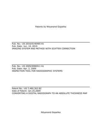
  • 5. Patent Application Publication Jun. 10, 2010 Sheet 3 of 6 US 2010/0140485 A1 0 0 <0 <0 -.-·. .~.: -~· + .·.: -~ . ~ ,. . -_- - -~ . -, _.- -_; . .: . ~ . .. -. . ·· .- ... ·: .··-- ._~ : . .:·- _.- - ·.. -· ~ . ·.· ~·· . -·: ' ·.' ~ :- II II «> «> 1.0 1.0 .................................. e e •• I I I I I ................................. . I I I I I I I I I ................................. I I I I I I I I I I I I I I I I I I I I I I I I I I I I I I I I I I I I I I I I I I I I I I I I ' ....................... . :::::::::::::::::::::::. ....................... .··~~~~~ ......................... . • • • • • • • • • • • • • • • • • • • • • • • • 0 .... .................. ........................ • • • .. • • • • • • • • • • • • • • • • • • • 0 ..... .................. . • I • I • I • I • I • I • I • I • I • I • I • I • I • I • I • I : : : : : : : : : : : : : : : : : : : : : : ;1'5..::'.-~~~"';. • I • I • I • I • I" I • • I 0 • I I I I. I I I I I I I e I e I I I e e I" I I ' .................................. . ........................... ................. . ..... .. . .... .... .. ................ ....... .......... ................................... ... . . ..... <0 <0 1.0 1.0 (.9 LL
  • 6. Patent Application Publication Jun. 10, 2010 Sheet 4 of 6 US 2010/0140485 A1 L{)
  • 7. '"= ~ ..... ~66 ('D = ..... ~ - .... 'e (') .... ~ ..... 0 70 = '"= 8 VCT system 1 .._80 = - .... 0" (') .... ~ ..... 0 Scatter grid image 72 = Raw data acquisition 1 '-82 2' := Centroid detection 74 .... ~0 N • C>l Subtract scatter image 84 .... 0 0 Interpolation to generate full scatter image rFJ 76 =- ('D ..... ('D Ul 0 Normalization and ..... 0 bad pixel correction 86 78 Compute scatter image for each angle and store. c rFJ N .... 0 ..._ 0 88 .... 0 .j;o. 0 .j;o. QO Ul FIG. 6 > ....
  • 8. Patent Application Publication Jun. 10, 2010 Sheet 6 of 6 US 2010/0140485 A1 _.-90 _.-92 FIG. 7 _.-94
  • 9. US 2010/0140485 AI Jun. 10,2010 1 IMAGING SYSTEM AND METHOD WITH [0005] As manufacturing tolerances become tighter, there SCATTER CORRECTION is a corresponding increase in the demands for metrology techniques for maintaining the tolerances. The need for qual- BACKGROUND ity and performance testing has become an integral part of the production or manufacturing process. Thus, in order to [0001] The invention relates generally to the field of non- improve CT inspection accuracy and efficiency, more effec- invasive imaging and more specifically to the field of com- tive methods are needed for removing scatter radiation related puted tomography (CT) imaging and inspection systems. In artifacts. Accordingly, a need exists for a measurement tech- particular, the invention relates to a technique for correcting nique that is relatively inexpensive, versatile and program- scatter from digital radiographs acquired via volumetric com- mable for different applications and that requires low main- puted tomography (VCT) systems. tenance. [0002] Inspection of objects is of vital importance in manu- [0006] It is therefore desirable to provide an improved scat- facturing and repair industries. Various types of inspection ter measurement and correction technique that accurately systems, such as computed tomography (CT), coordinate measures scatter radiation in the projection images and measuring machines (CMM), laser-based profilometry, light removes the same from the projection images, thereby gauge, infrared and others, are used in industrial inspection improving the VCT image quality. It is also desirable that the processes for a wide variety of applications. For example, improved scatter measurement and correction technique is these inspection systems may be used for measuring dimen- inexpensive and computationally efficient and time efficient, sions or for identifying defects in manufactured parts, such as thereby increasing the throughput of the VCT system. turbine blades. Each of these inspection systems has its advantages and disadvantages. Modalities such as CMM and BRIEF DESCRIPTION laser-based profilometry typically measure external surfaces [0007] Briefly, in accordance with one aspect of the present with high accuracy, but cannot measure internal features invention, a method is provided for imaging an object. The unless the object is cut open. To date, CT is the most versatile method provides for acquiring a first projection image of the of the measurement/inspection systems for revealing both the object using a source and a detector. The first projection internal and external structures of industrial parts in a non- image includes a primary image of the object and a scatter destructive manner. Because of their ability to provide inter- image of the object. The method also provides for positioning nal as well as external measurements, CT based techniques a scatter rejection plate between the object and the detector, may facilitate processes such as reverse engineering, rapid and acquiring a second projection image of the object with the prototyping, casting simulation and validation, tire develop- scatter rejection plate disposed between the object and the ment, first article inspection, ceramic porosity inspection, detector. The second projection image includes the primary process validation, parts qualification and defect detection, image of the object. The method further provides for gener- among others. However, CT based techniques may also have ating a scatter image of the object based on the first projection certain limitations, which may deter their widespread use. image and the second projection image, and storing the scat- [0003] For example, volumetric computerized tomography ter image of the object for subsequent imaging. Systems and (VCT) imaging for industrial applications (e.g., imaging of computer programs that afford such functionality may be metallic parts) typically provides unsatisfactory images hav- provided by the present invention. ing image artifacts due to radiation-matter interaction based [0008] In accordance with another aspect of the present artifacts, scanner based artifacts, reconstruction techniques invention, a method is provided for imaging an object. The based artifacts, and so forth. The radiation-matter interaction method provides for acquiring a plurality of projection based artifacts may further include beam hardening artifacts images of the object using a source and a detector oriented at and artifacts due to x-ray scatter radiations. Scatter radiation a plurality of projection angles relative to the object, and in the projection images reduces the contrast of the projection generating a plurality of scatter free projection images by images, produces degradation of or blurs sharp features of the correcting the plurality of projection images based on respec- object in the generated volume images, and reduces the accu- tive ones of a plurality of stored scatter images. The scatter racy of metrology applications and the detectability of images are generated and stored for each of the projection smaller features. Scatter radiation is a strong function of the angles by positioning a scatter rejection plate between the imaging parameters such as the object under imaging, beam object and the detector. The method further provides for spectrum used, geometrical distances, and the surrounding reconstructing a three-dimensional image of the object based medium. Due to various dependencies in the imaging param- on the scatter free projection images. Here again, systems and eters, an accurate estimation of the scatter signal content in computer programs affording such functionality may be pro- projection imaging is challenging. Physics-based models are vided by the present invention. often used for predicting scatter content in x-ray images, [0009] In accordance with an additional aspect of the however they are time consuming and predict only scatter present invention, a volumetric CT system is provided for arising out of the object under scanning, provided the material imaging an object. The volumetric CT system includes a properties are known. source and a detector configured to move with respect to the [0004] There exist different techniques for scatter measure- object. The detector is further configured to acquire a plural- ment and scatter correction in acquired projection images. ity of projection images of the object from a plurality of For example, one popular scatter measurement technique projection angles. The volumetric CT system further includes employs a beam stopper located between the radiation source a processor configured to generate a plurality of scatter free and the object being scanned in a VCT system to measure the projection images by correcting the projection images based scatter at a corresponding location. However, most currently on respective stored scatter images, and to reconstruct a three- known techniques primarily address the object scatter and dimensional image of the object based on the scatter free involve time-consuming computer simulations. projection images. The scatter images are generated and
  • 10. US 2010/0140485 AI Jun. 10,2010 2 stored for each of the projection angles by employing a scatter positioned. Non-limiting examples of the object 12 include rejection plate positioned between the object and the detector. industrial parts, including but not limited to turbine airfoils, blades, disks, and shafts. It should be noted that a particular DRAWINGS region of the object 18 may be chosen by an operator for imaging so that the most useful scan of the region may be [001 0] These and other features, aspects, and advantages of acquired. the present invention will become better understood when the [0020] A portion of the radiation 20 passes through or following detailed description is read with reference to the around the object 18 and impacts the detector array 16. The accompanying drawings in which like characters represent detector array 16 may be an area detector and is generally like parts throughout the drawings, wherein: formed as a two-dimensional array of detection elements. In [0011] FIG. 1 depicts an exemplary flat panel VCT system one implementation, the detector array 16 may be a flat-panel for imaging an object in which aspects of the present tech- detector formed as rows and colunms of detector elements nique may be practiced; that may be individually read out. Each detector element [0012] FIGS. 2 and 3 depicts scatter rejection plates in produces an electrical signal that represents the intensity of accordance with aspects of the present technique for use in the incident radiation 20 at the detector element when the flat panel VCT system of FIG. 1; radiation 20 strikes the detector array 16. Typically, signals [0013] FIG. 4 depicts a schematic for generating a scatter are acquired at one or more view angle positions around the grid image by employing the scatter rejection plates of FIGS. object 18 so that a plurality of radiographic views may be 2 and 3 in accordance with aspects of the present technique; collected. These signals are acquired and processed to recon- [0014] FIG. 5 depicts a schematic for interpolating the scat- struct an image of the features internal as well as external to ter grid image obtained by the technique ofFIG. 4 to generate the object 18. a complete scatter image in accordance with aspects of the [0021] The object 18, the radiation source 12, and the present technique; detector array 16 are typically displaced relative to each other, [0015] FIG. 6 depicts a control logic for inspecting an allowing projection data to be acquired at various views rela- object via the flat panel VCT system of FIG. 1 by employing tive to the object 18 if desired. For example, in one imple- a scatter measurement and correction technique in accor- mentation, the object 18 may be positioned on a table, such as dance with aspects of the present technique; and a turntable, so that the object 18 may be rotated during the [0016] FIG. 7 depicts, for a turbine fan blade, uncorrected examination process to expose the object 18 to the stream of image and scatter corrected images by employing the control radiation 14 from all sides. Alternatively, the radiation source logic of FIG. 6. 12 and/or the detector array 16 may be disposed on a gantry, which may be rotated around the object 18 placed on a table DETAILED DESCRIPTION during the examination process. Further, in certain embodi- [0017] The present techniques are generally directed to ments, components of the imaging system as well as the computed tomography (CT) imaging resulting in improved imaged object may be moved during the examination process image quality. Such imaging techniques may be useful in a to acquire projection images at different views. As the object variety of imaging contexts, such as medical imaging, indus- 18 and the radiation source 12 rotate relative to each other, the trial metrology and inspection, security screening, baggage or detector array 16 collects data of radiation attenuation at the package inspection, and so forth. Moreover, such imaging various view angles relative to the object 18. techniques may be employed in a variety of imaging systems, [0022] Data collected from the detector array 16 then typi- such as CT systems, tomosynthesis systems, X-ray imaging cally undergoes pre-processing to condition the data to rep- systems, and so forth. Though the present discussion provides resent the line integrals of the attenuation coefficients of the examples in an industrial inspection context with respect to scanned objects 18. The processed data, commonly called CT systems resulting in improved measurement and inspec- projections, are then reconstructed to formulate a volumetric tion accuracy, one of ordinary skill in the art will readily image of the scanned area, as discussed in greater detail apprehend that the application of these techniques in other below. contexts and in other systems is well within the scope of the [0023] Operation of the source 12 is controlled by a system present techniques. controller 22, which furnishes both power, and control signals [0018] Referring now to FIG. 1, an imaging system 10 for for examination sequences. Moreover, the detector array 16 is use in accordance with the present technique is illustrated. In coupled to the system controller 22, which commands acqui- the illustrated embodiment, the imaging system 10 is a volu- sition of the signals generated in the detector array 16. The metric computed tomography (VCT) system designed both to system controller 22 may also execute various signal process- acquire image data and to process the image data for display ing and filtration functions, such as for initial adjustment of and analysis in accordance with the present technique. In the dynamic ranges, interleaving of digital image data, and so illustrated embodiment, the imaging system 10 includes a forth. In general, the system controller 22 commands opera- radiation source 12, such as an X-ray source. A collimator tion of the imaging system 10 to execute examination proto- may be positioned adjacent to the radiation source 12 for cols and to process acquired data. In the present context, regulating the size and shape of a stream of radiation 14 that system controller 22 may also include signal processing cir- emerges from the radiation source 12. cuitry and other circuitry, typically based upon a general [0019] In typical operation, the radiation source 12 projects purpose or application-specific digital computer, with asso- a stream of radiation 14, such as an X-ray beam, towards a ciated memory circuitry. The associated memory circuitry detector array 16 placed on the opposite side of the radiation may store programs and routines executed by the computer, source 12, relative to the imaged object. The stream of radia- configuration parameters, image data, and so forth. For tion 14 passes into an imaging volume in which an object 18, example, the associated memory circuitry may store pro- such as a turbine blade or other item to be imaged may be grams or routines for implementing the present technique.
  • 11. US 2010/0140485 AI Jun. 10,2010 3 [0024] In the embodiment illustrated in FIG. 1, the system [0028] The processor 34 is typically used to control the controller 22 is coupled to a linear positioning subsystem 24 imaging system 10. The processor 34 may also be adapted to and a rotational subsystem 26. In particular, the system con- control features enabled by the system controller 22, i.e., troller 22 may include a motor controller 28 that controls the scanning operations and data acquisition. Indeed, the system operation of the linear positioning subsystem 24 and the controller 22 may be implemented as hardware and software rotational subsystem 26. The rotational subsystem 26 enables components of the depicted processor 34. In addition, the the X -ray source assembly and/or the detector assembly to be processor 34 may be configured to receive commands and rotated around the object or the patient 18. It should be noted scanning parameters from an operator via an operator work- that the rotational subsystem 26 may include a gantry. Thus, station 38. For example, the operator workstation 38 may be the system controller 22 may be utilized to control the rota- equipped with a keyboard and/or other input devices by tional speed and position of the gantry. Alternatively, the which an operator may control the imaging system 10. Thus, rotational subsystem 26 may include a motorized turntable the operator may observe the reconstructed image and other and the system controller 22 may be configured to rotate the data relevant to the system from processor 34, initiate imag- motorized turntable, thereby rotating the object 18 one or ing and so forth. Where desired, other computers or worksta- multiple turns during an examination. The linear positioning tions may perform some or all of the functions of the present subsystem 24 enables the object 18 to be displaced linearly, technique, including post-processing of image data simply such as by moving a table or support on which the object 18 accessed from memory device 36 or another memory device rests. Thus, in one embodiment, the table may be linearly at the imaging system location or remote from that location. moved within a gantry to generate images of particular areas [0029] A display 40 may be coupled to one of the operator of the object 18. In another embodiment (e.g., in a tomosyn- workstation 38 and the processor 34 and may be utilized to thesis system), the X-ray source may be moveable using a observe the reconstructed image and/or to control imaging. linear positioning subsystem. The detector position may be Additionally, the scanned image may also be printed by a variable, but not be controlled using a positioning subsystem. printer 42 which may be coupled to the processor 34 and/or It should be noted that other configurations may also be used. the operator workstation 38, either directly or over a network. [0025] Additionally, as will be appreciated by those skilled It should be further noted that the processor 34 and/or opera- in the art, the radiation source 12 may be controlled by a tor workstation 38 may be coupled to other output devices radiation controller 30 disposed within the system controller that may include standard or special purpose computer moni- 22. Particularly, the radiation controller 30 may be configured tors and associated processing circuitry. Furthermore, addi- to provide power and timing signals to the radiation source tional operator workstations may be further linked in the 12. Further, the system controller 22 may include data acqui- imaging system 10 for outputting system parameters, sition circuitry 32. In this exemplary embodiment, the detec- requesting inspection, viewing images, and so forth, so that tor array 16 is coupled to the system controller 22, and more more than one operator may perform operations related to the particularly to the data acquisition circuitry 32. The data imaging system 10. For example, one operator may utilize acquisition circuitry 32 typically receives sampled analog one operator workstation to image acquisition while a second signals from the detector array 16 and converts the data to operator utilizes a second operator workstation to reconstruct digital signals for subsequent processing by a processor 34. and/or review the results of the imaging routines. In general, Such conversion, and indeed any preprocessing, may actually displays, printers, workstations, and similar devices supplied be performed to some degree within the detector assembly within the imaging system 10 may be local to the data acqui- itself. sition components, or may be remote from these components [0026] The processor 34 is typically coupled to the system linked to the imaging system 10 via one or more configurable controller 24. Data collected by the data acquisition circuitry networks, such as the Internet, virtual private networks, and 32 may be transmitted to the processor 34 for subsequent so forth. processing and reconstruction. Reconstruction of the image [0030] The exemplary imaging system 10, as well as other may be done by general or special purpose circuitry of the imaging systems based on radiation attenuation, may employ processor 34. Once reconstructed, the image produced by the a variety of scatter mitigation and/or correction techniques for imaging system 10 reveals internal as well as external fea- improving the image quality. For example, the present tech- tures of the object 18. Alternatively, an image reconstructor, nique employs scatter rejection plates, depicted in FIGS. 2 that is coupled to or is a part of a processor 34, may receive and 3 and represented generally at reference numeral 44, for sampled and digitized data from the data acquisition circuitry rejecting the scatter radiation resulting from object as well as 32 and may perform high-speed image reconstruction to gen- those resulting from the background in accordance with erate one or more images of the scanned object 18. aspects of the present technique. [0027] The processor 34 may include or be in communica- [0031] In one embodiment, the scatter rejection plate 44 tion with a memory 36. It should be understood that any type may be an aperture plate 46, as illustrated in FIG. 2. The of computer accessible memory device suitable for storing aperture plate 46 includes a plurality of sub-centimeter sized and/or processing such data and/or data processing routines circular apertures 48 drilled in a plate 50. In certain embodi- may be utilized by such an exemplary imaging system 10. ments, the apertures may be about 1-2 millimeters in diameter Moreover, the memory 36 may comprise one or more spaced apart at about 5 millimeters from each other (center- memory devices, such as magnetic or optical devices, of to-center). Alternatively, the scatter rejection plate 44 may be similar or different types, which may be local and/or remote a collimator plate 52, as illustrated in FIG. 3. The collimator to the system 10. The memory 36 may store data, processing plate 52 includes a plurality of sub-centimeter sized horizon- parameters, and/or computer programs comprising one or tal or vertical slots 54 drilled in a plate 50. In certain embodi- more routines for performing the processes described herein. ments, the slots may be about 1-2 millimeters in width spaced Furthermore, memory 36 may be coupled directly to system apart at about 5 millimeters from each other (center-to-cen- controller 24 to facilitate the storage of acquired data. ter). Typically, the plate 50 is thick and made of high-density
  • 12. US 2010/0140485 AI Jun. 10,2010 4 material. The high-density material may be, for example, interpolated based on the detected aperture points to generate lead, tungsten or a tungsten alloy, molybdenum, tantalum or a full or complete scatter image of the object at step 64. In rhenium. In certain embodiments, the plate is about 10 mil- other words, the data points are first mapped to a regular grid limeters in thickness. and then interpolated using shape factors. As will be appre- [0032] Further, various other scatter rejection plates may be ciated by those skilled in the art, any type of interpolation designed based on the specific imaging applications and techniques may be employed to generate the scatter image requirements, so as to optimize scatter rejection performance. from the scatter grid image. Non-limiting examples of the For example, different variants of each of the two types of interpolation techniques include bi-linear interpolation, plates for scatter rejection (aperture plate and collimator piecewise constant interpolation, bi -cubic interpolation, mul- plate) may be designed. In certain embodiments, if the geom- tivariate interpolation, and so forth. etry of an x-ray setup is fixed, focally aligned apertures or [0036] As will be appreciated by those skilled in the art, a collimators may be designed. This provides that no primary scatter image of the object is generated for each of the pro- x-ray beam deflect at wide angles. In other words, the aper- jection angles. The generated scatter images are stored in the tures 48 or the slots 54 may be drilled at an angle parallel to memory for subsequent imaging. As will be appreciated by the angle of incidence of the X -ray beam, so as to maximize those skilled in the art, subsequent imaging includes acquir- the rejection of scatter radiation. Similarly, the aperture plate ing projection images of the object from various projection or the collimator plate may be optimized for a particular angles and generating scatter free projection images for each X-ray energy application. Further, it should be noted that the projection angle based on the projection images and respec- spacing of the apertures or collimators may be based on tive stored scatter images. The scatter free projection images specific applications depending on cost and image quality are generated by correcting the projection images based on requirements. respective ones of stored scatter images. In certain embodi- [0033] The flat panel VCT system 10 employs the scatter ments, the scatter free projection images may be corrected by rejection plates 44 for generating initial scatter image of the subtracting the respective pre-stored scatter images from the object 18 in accordance with aspects of the present technique. acquired projection image for each of the projection angle. It For example, as illustrated in the schematic of FIG. 4, the should be noted that the orientation of the object during VCT system 10 acquires a first projection image 56 of the subsequent imaging should be substantially same as it was object 18 without the scatter rejection plate 44. This first during generation of scatter image for each projection angles. projection image 56 includes a primary image of the object as The scatter free projection images may be further processed well as a scatter image of the object. The VCT system 10 then to normalize and correct for any bad pixels in the scatter free acquires a second projection image 58 of the object with the projection images. The generated or processed scattered free scatter rejection plate 44 positioned between the object 18 projection images may then be reconstructed to generate a and the detector 16. This second projection image 58 includes three-dimensional image of the object. As will be appreciated only the primary image of the object 18. As will be appreci- by those skilled in the art, any suitable reconstruction tech- ated by those skilled in the art, the primary image is free from nique may be employed for the image reconstruction. Non- any artifacts caused due to scatter radiation. Further, it should limiting examples of the reconstruction techniques include be noted that, in the second projection image, the primary filtered back projection (FBP), iterative filtered back projec- image of the object 18 is formed only at certain discrete tion (IFBP), iterative reconstruction and/or statistical recon- locations where measurements are obtained through the aper- struction techniques. tures or slots and is therefore dependent on the type of scatter [0037] The exemplary imaging system 10 may generate rejection plate 44 employed to acquire the image. The illus- images of the object under examination by the techniques trated embodiment depicts the primary image acquired by discussed herein. In particular, as will be appreciated by those using aperture plate 46 as well as the primary image acquired of ordinary skill in the art, control logic and/or automated by using collimator plate 52. The first image 56 and the routines for performing the techniques and steps described second projection image 58 may also be referred as non-grid herein may be implemented by the imaging system 10 ofFIG. image 56 and grid image 58 respectively. 1, by hardware, software, or combinations of hardware and [0034] The VCT system 10 then generates the scatter image software. For example, suitable code may be accessed and of the object at the respective one of the projection angles executed by the processor 34 to perform some or all of the based on the first projection image 56 and the second projec- techniques described herein. Similarly application specific tion image 58. In particular, the processor 34 subtracts the integrated circuits (ASICs) configured to perform some or all second projection image 58 from the first projection image 56 of the techniques described herein may be included in the to generate a scatter grid image 60. It should be noted that processor 34 and/or the system controller 22. acquisition of the first projection image 56 and the second [0038] For example, referring now to FIG. 6, exemplary projection image 58, and the generation of scatter grid image control logic for inspecting an object by employing scatter 60 are performed for each of the projection angles. measurement and correction technique on the imaging sys- [0035] The generated scatter grid image 60 is then interpo- tem such as flat panel VCT system 10 is depicted in accor- lated to generate a complete scatter image. FIG. 5 depicts an dance with aspects of the present technique. As illustrated in example schematic for interpolating a scatter grid image the flowchart 66, a non-grid image and a grid image may be obtained by the technique of FIG. 4 to generate a complete acquired for a given object at multiple projection angles via scatter image in accordance with aspects of the present tech- the VCT system at steps 68 and 70 respectively. As discussed nique. As illustrated, all aperture points or centroids for the above, the grid image may be acquired by employing the scatter grid image are first detected at step 62. It should be scatter rejection plate positioned between the object and the noted that, for the scatter grid image acquired by employing a detector. A scatter grid image is then generated based on the collimator plate, the aperture points may be detected based on non-grid image and the grid image at step 72. The scatter grid the required pixel resolution. The scatter grid image is then image is then processed to detect multiple aperture points or
  • 13. US 2010/0140485 AI Jun. 10,2010 5 centeroids at step 74. Based on the detected centeroids, the orientation, and x-ray technique prior to a VCT scan and use scatter grid image is then interpolated to generate a full scatter it during an actual imaging scan. This improves the through- image of the given object at step 76. The process is repeated put of the VCT system since scatter correction for the projec- for each of the multiple projection angles and the generated tion images is then a simple image subtraction process. Fur- scatter images for the respective projection angles are stored ther, as will be appreciated by those skilled in the art, it is for subsequent imaging applications at step 78. easier to measure primary radiation than the scatter radiation [0039] During subsequent imaging, the VCT system and positioning the scatter rejection plate between the object images the object at step 80 and acquires projection images of and the detector makes the measurement of primary radiation the object from various projection angles at step 82. It should substantially convenient. Additionally, the use of narrow col- be noted that, the projection images are acquired for same limators permits the imaging of the higher spatial frequency projection angles for which the scatter images have been content of the scatter images. Moreover, the technique per- generated. The scatter free projection images are then gener- mits capture and correction of the beam scatter (scatter due to ated based on the projection images and corresponding scat- the imaged object) as well as the background radiation scatter ter images at step 84. In one embodiment this is done by (scatter due to external object). subtracting the corresponding scatter images from the [0043] Further, as will be appreciated by those skilled in the acquired projection images. The scatter free projection art, the technique may be employed as a part of the system images are then post processed at step 86. The post processing calibration process prior to the actual imaging application. may involve normalization and correction for bad pixels. The Typically, prior to performing VCT imaging for metrology or processed scatter free projection images are then recon- inspection, an operator has to perform a few system calibra- structed to generate a three-dimensional image of the object tion steps such as, flat field calibration of the detector, bad at step 88. pixel test and calibration of the detector, geometrical align- [0040] FIG. 7 illustrates, for a turbine fan blade, uncor- ment and calibration of the system. The scatter correction rected image and scatter corrected images by employing con- technique described in the embodiments discussed above trol logic of FIG. 6. Image 92 is the uncorrected image may similarly become a part of the calibration process where obtained by a typical VCT system, while images 94 and 96 are the scatter images will be obtained for a specific object and scatter corrected images obtained by employing the scatter stored prior to the performance of an actual metrology or rejection plate and the control logic described via the flow- inspection process. chart 66. Further, it should be noted that image 94 is the [0044] While only certain features of the invention have scatter corrected image obtained by employing aperture plate, been illustrated and described herein, many modifications while image 96 is the scatter corrected image obtained by and changes will occur to those skilled in the art. It is, there- employing collimator plate. fore, to be understood that the appended claims are intended [0041] It should be noted that one or more imaging param- to cover all such modifications and changes as fall within the eters should be substantially maintained (that is, maintained true spirit of the invention. at substantially similar values) for a particular imaging appli- cation and inspection requirement. Non-limiting examples of the imaging parameters include a type of object being 1. A method for imaging an object, the method comprising: imaged, a shape and an orientation of the object being acquiring a first projection image of the object using a imaged, projection angles from which the scatter images and source and a detector, the first projection image com- subsequent projection images are acquired, an x-ray tech- prising a primary image of the object and a scatter image nique being employed, a geometry and one or more settings of the object; of the source and the detector, distance of the scatter rejection positioning a scatter rejection plate between the object and plates from the source and the detector, and so forth. For the detector; example, the above process may be set for imaging similar acquiring a second projection image of the object with the objects (e.g., turbine blades). The objects should be mounted scatter rejection plate disposed between the object and on the turntable at substantially similar orientations. Further, the detector, the second projection image comprising the the distance of the scatter rejection plate from the source and primary image of the object; the detector should be substantially maintained while acquir- generating a scatter image of the object based on the first ing and storing the scatter images for each of the predeter- projection image and the second projection image; and mined projection angles. In one embodiment, this may be storing the scatter image of the object for subsequent imag- achieved by coupling or attaching the scatter rejection plate to ing. the two-dimensional flat panel detector array. Additionally, projection images should be acquired for projection angles 2. The method of claim 1, wherein generating the scatter for which the scatter images have been generated and stored. image further comprises generating a scatter grid image by Moreover, the x-ray technique employed, the geometry and subtracting the second projection image from the first projec- other settings for the source and the detector should be main- tion image. tained at substantially similar values, such that the beam 3. The method of claim 2, wherein generating the scatter shape and intensity are same for various image acquisitions. image further comprises detecting a plurality of aperture [0042] As will be appreciated by those skilled in the art, the points for the scatter grid image and interpolating the scatter scatter correction techniques described in the various grid image based on the aperture points. embodiments discussed above permit a measurement of the 4. The method of claim 1, wherein the scatter image is scatter content in the projection images used for VCT imag- stored for each of a plurality of projection angles. ing and correct the projection images, thereby improving the 5. The method of claim 1, wherein subsequent imaging VCT image quality. The technique permits measurement of comprises acquiring a plurality of projection images of the scatter content in x-ray images for a given geometry, scanning object from a plurality of projection angles.
  • 14. US 2010/0140485 AI Jun. 10,2010 6 6. The method of claim 5, wherein subsequent imaging 16. The method of claim 15, wherein generating the scatter comprises generating a plurality of scatter free projection images for each of the respective projection angles com- images based on the projection images and respective scatter prises: images. acquiring a first projection image of the object, the first 7. The method of claim 6, wherein subsequent imaging projection image comprising a primary image of the comprises reconstructing a three-dimensional image of the object and the scatter image of the object; object based on the scatter free projection images. positioning the scatter rejection plate between the object and the detector; 8. The method of claim 7, wherein reconstructing com- acquiring a second projection image of the object with the prises normalizing and correcting at least one bad pixel in a scatter rejection plate disposed between the object and plurality of scatter free projection images. the detector, the second projection image comprising the 9. The method of claim 1, further comprising maintaining primary image of the object; and a plurality of substantially similar imaging parameters. generating the scatter image of the object based on the first 10. The method of claim 9, wherein the imaging param- projection image and the second projection image. eters are selected from the group consisting of a type of object 17. The method of claim 15, wherein correcting the pro- being imaged, a shape and an orientation of the object being jection images comprises subtracting the scatter images from imaged, projection angles from which the scatter images and the respective projection images. subsequent projection images are acquired, an x-ray tech- 18. A volumetric CT system for imaging an object, the nique being employed, a geometry and one or more settings system comprising: of the source and the detector, and combinations thereof. a source and a detector configured to move with respect to the object, wherein the detector is further configured to 11. The method of claim 1, wherein the scatter rejection acquire a plurality of projection images of the object plate is designed based on a type of imaging application so as from a plurality of projection angles; and to optimize scatter rejection performance. a processor configured to generate a plurality of scatter free 12. The method of claim 1, wherein the scatter rejection projection images by correcting the projection images plate comprises at least one of an aperture plate or a collima- based on respective stored scatter images and to recon- tor plate. struct a three-dimensional image of the object based on 13. The method of claim 12, wherein the aperture plate the scatter free projection images, wherein the scatter comprises a high density material and defines a plurality of images are generated and stored for each of the projec- sub-centimeter sized circular apertures. tion angles by employing a scatter rejection plate posi- 14. The method of claim 12, wherein the collimator plate tioned between the object and the detector. comprises a high density material and defines a plurality of 19. The system of claim 18, wherein for each of the pro- sub-centimeter sized horizontal or vertical slots. jection angles, the detector is further configured to acquire a first projection image of the object and a second projection 15. A method for imaging an object, the method compris- image of the object with the scatter rejection plate positioned ing: between the object and the detector, and wherein the proces- acquiring a plurality of projection images of the object sor is further configured to generate the scatter image of the using a source and a detector oriented at a plurality of object at the respective one of the projection angles based on projection angles relative to the object; the first projection image and the second projection image. generating a plurality of scatter free projection images by 20. The system of claim 18, wherein the scatter rejection correcting the plurality of projection images based on plate is designed based on a type of imaging application so as respective ones of a plurality of stored scatter images, to optimize scatter rejection performance. wherein the scatter images are generated and stored for 21. The system of claim 18, wherein the scatter rejection each of the projection angles by positioning a scatter plate comprises at least one of an aperture plate or a collima- rejection plate between the object and the detector; and tor plate. reconstructing a three-dimensional image of the object based on the scatter free projection images. * * * * *