1. Workshop 2
Creating Native Geometry: Pipe Creep Model
Introduction
Creep is the permanent elongation of a component under a static load maintained for a
period of time. Most metals and their alloys creep only at elevated temperatures, but
several materials such as thermoplastics and rubbers do so at room temperature.
Designers estimating the service life and structural integrity of components must account
for creep effects in their designs.
This model represents the intersection of a pipe with a cylindrical pressure vessel. The
system operates at elevated temperature and carries internal pressure. The calculation
consists of two steps. In the first step a static analysis is performed, during which the
internal pressure is applied. In the second step a transient analysis is carried out to
determine the creep behavior of the pressurized vessel and pipe.
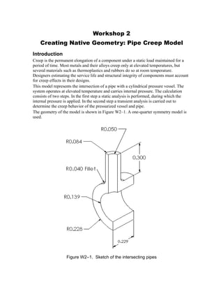
The geometry of the model is shown in Figure W2–1. A one-quarter symmetry model is
used.
Figure W2–1. Sketch of the intersecting pipes
2. Note: The part created in this workshop will be used in subsequent workshops to build
the complete model and perform the analysis. It is important that you use the dimensions
stated and not deviate from the workshop instructions; otherwise, you may find it difficult
to complete the subsequent workshops.
Starting ABAQUS/CAE
Start a new session of ABAQUS/CAE from the workshops/pipeCreep directory by
typing
abaqus cae
at the operating system prompt, where abaqus is the command used to run ABAQUS on
your system. Select Create Model Database from the Start Session dialog box that
appears.
Defining the model geometry
As always, the first step in creating the model is to define its geometry. In this example
you will create a three-dimensional, deformable body to model the pipe intersection.
You need to decide what system of units to use in your model. The SI system of meters,
kilograms, and hours is used here; you can use another system if you prefer.
To create a part:
1. From the Module list located under the toolbar, select Part to enter the Part
module.
2. From the main menu bar, select PartCreate to create a new part. Name the
part pipe-intersection and accept the default settings of a three-
dimensional, deformable body and a solid, extruded base feature in the Create
Part dialog box. In the Approximate size text field, type 2. This value is
approximately 5 times the outer diameter of the vessel. Click Continue to exit
the Create Part dialog box.
W2.2
3. 3. Open the Sketcher Options dialog box by clicking on the customization tool
from the Sketcher toolbox. Change the Grid spacing to 0.02 and
Decimal places (for sketch dimensions) to 3. Click OK to close the dialog box
and to apply the changes.
4. Use the Create Circle: Center and Perimeter tool to sketch two
concentric circles of radii 0.24 m and 0.14 m, respectively, centered at the
origin. For convenience, align the perimeter points along the X-axis of the sketch
plane, as shown in Figure W2–2.
5. Use the Create Dimension: Radial tool to dimension the values of the
radii as shown in Figure W2–2.
Figure W2–2. Concentric circles
6. Select the Edit Dimension Value tool from the toolbox. Click on the
0.240 dimension in the viewport, and enter a new value of 0.228 m in the
prompt area. Click mouse button 2 to modify the dimension. (Mouse button 2 is
the middle mouse button on a 3-button mouse; on a 2-button mouse, press both
mouse buttons simultaneously.) Similarly, modify the radius of the inner circle to
0.139 m as shown in Figure W2–3.
Perimeter points
W2.3
4. Figure W2–3. Modified dimensions of the circles
7. In the prompt area, click Done to continue.
8. The Edit Base Extrusion dialog box appears. Enter a value of 0.458 m for
the depth of the solid extrusion and click OK.
9. In the toolbar, click the Render Model: Shaded tool to change the render
style to shaded, as shown in Figure W2–4.
Figure W2–4. Shaded render style
The cross-section of the intersecting pipe must be sketched on a planar region and
then extruded. Since the outer surface of the vessel is cylindrical, a datum plane
will be created and used for the purpose of sketching the intersecting pipe.
10. From the main menu bar, select ToolsDatum.
11. In the Create Datum dialog box, choose Plane as the type and Offset from
principal plane as the method.
12. Click OK.
13. In the prompt area, choose the XZ Plane as the plane from which to offset.
W2.4
5. 14. Specify an offset distance of 0.528 m. Click the Auto-Fit View tool in the
toolbar to resize the view. The datum plane is shown in Figure W2–5.
15. From the main menu bar, select ToolsDatum.
16. In the Create Datum dialog box, choose Axis as the type and Principal Axis
as the method.
17. Click OK.
18. Create a principal X-Axis as shown in Figure W2–5.
Figure W2–5. Datum geometry
19. From the main menu bar, select ShapeSolidExtrude. Do the following:
A. In the viewport, select the datum plane as the plane on which to create the
sketch.
B. Select the datum axis as the edge that will appear vertical and on the right of
the sketch.
Datum plane
Datum axis
W2.5
6. Figure W2–6. Solid extrusion: sketch plane and axis
C. Sketch a circle of radius 0.08 m centered in the plane. Place the perimeter
point of the circle on the negative horizontal axis of the sketch plane. The
reason for this is that the model will later be quartered such that only the
upper-right quadrant of the part will be retained. By placing the perimeter
point outside of this quadrant, we ensure that no redundant edges will persist
afterwards. Dimension the radius of the circle, and modify the dimension to be
0.084 m.
D. Click mouse button 2 to continue, and click Done in the prompt area.
E. In the Edit Extrusion dialog box, choose the end condition Blind and
extrude the solid a depth of 0.35 m. Flip the extrusion direction so that it is
pointing toward the vessel, as shown in Figure W2–7. Click OK.
W2.6
7. Figure W2–7. Arrow direction for solid extrusion
20. From the main menu bar, select ShapeCutExtrude. Do the following:
A. Select the end plane on the smaller pipe as the plane on which to sketch, as
shown in Figure W2–8.
F. Select the datum axis as the edge that will appear vertical and on the right.
G. Sketch a circle of radius 0.04 m concentric with the circle representing the
pipe. As before, place the perimeter point of the circle on the negative
horizontal axis of the sketch plane. Dimension the radius of the circle, and
modify the dimension to be 0.05 m.
H. Click mouse button 2 to continue, and click Done in the prompt area.
I. In the Edit Cut Extrusion dialog box, choose the end condition Blind and
extrude the cut a depth of 0.528 m. The direction of extrusion is into the
pipe, as shown in Figure W2–8. Click OK.
W2.7
8. Figure W2–8. Solid cut
21. From the main menu bar, select ShapeBlendRound/Fillet. Select the edge
around the intersection as the edge to be rounded, as shown in Figure W2–9.
Specify a fillet radius of 0.04 m.
Figure W2–9. Rounded edge
22. Quarter the model as follows:
A. From the main menu bar, select ShapeCutExtrude.
J. Select the end face of the smaller pipe as the plane on which to sketch.
K. Select the datum axis as the edge that will appear vertical and on the right.
L. Using the Create Lines: Connected tool located in the upper right-hand
corner of the Sketcher toolbox, sketch the series of connected lines shown in
Figure W2–10.
W2.8
Sketch plane
Direction of extrusion
Edge that will appear
vertical
and on the right
Edge to be rounded
9. M. In the Edit Cut Extrusion dialog box, choose the Through All end
condition and the direction of extrusion into the pipe. Click OK.
Figure W2–10. Cut profile
The quarter symmetry model of the pipe intersection is shown in Figure W2–11.
Figure W2–11. Final geometry
23. From the main menu bar, select FileSave to save your model in a model
database file. You will continue building this model in subsequent workshops.
W2.9
Because of how the
perimeter points were
placed, the edge of the
fillet will be removed with
this cut. This will
facilitate structured
meshing in a later
workshop.