SKT100 Manual: Program Transponders and Keys
•
0 likes•252 views

The SKT100 manual provides instructions for using a device to program transponders from various manufacturers including Texas Instruments, Atmel, Sokymat, and Phillips. The SKT100 can read and write transponder keys, recover lost keys using built-in calculators, and generate prepared keys. It connects to a computer via USB to be controlled with software that allows selecting the transponder type and performing operations like reading, writing, and cloning transponder data. The manual describes the software interface and provides step-by-step instructions for operating with different transponder types.

Recommended
More Related Content
What's hot
What's hot (19)
Viewers also liked
Viewers also liked (20)
Similar to SKT100 Manual: Program Transponders and Keys
Similar to SKT100 Manual: Program Transponders and Keys (20)
Recently uploaded
Recently uploaded (20)
SKT100 Manual: Program Transponders and Keys
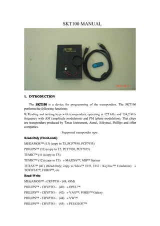
- 1. SKT100 MANUAL 1. INTRODUCTION The SKT100 is a device for programming of the transponders. The SKT100 performs the following functions: 1. Reading and writing keys with transponders, operating at 125 kHz and 134,2 kHz frequency with AM (amplitude modulation) and PM (phase modulation). That chips are transponders produced by Texas Instrument, Atmel, Sokymat, Phillips and other companies. Supported transponder type: Read-Only (Fixed-code) MEGAMOS™ (13) (copy to T5, PCF7930, PCF7935) PHILIPS™ (33) (copy to T5, PCF7930, PCF7935) TEMIC™ (11) (copy to T5) TEMIC™ (12) (copy to T5) » MAZDA™, MB™ Spriner TEXAS™ (4C) (Read-Only; copy to Silca™ EH1, EH2 / Keyline™ Emulators) » TOYOTA™, FORD™, etc. Read-Write MEGAMOS™ - CRYPTO - (48, 48M) PHILIPS™ - CRYPTO - (40) » OPEL™ PHILIPS™ - CRYPTO - (42) » VAG™, FORD™ Galaxy PHILIPS™ - CRYPTO - (44) » VW™ PHILIPS™ - CRYPTO - (45) » PEUGEOT™
- 2. PHILIPS™ - CRYPTO2 - (46) T5 (for coping 11,12,13,33) TEXAS™ - CRYPTO DST (4D) (ID 60,61,62,63,xx) TEXAS™ - CRYPTO DST+ (4E) (ID 64) 2. Recovering the lost keys(transponders) with data read from the car immobilizers memory using built-in calculators. 3. Generationing prepared keys for binding key to immobilizers by means of dealer equipment or other. The appearance of the SKT100 presented in the figure A below. Display, control buttons and transponder reading/writing coil located on face plate of the device. USB and additional power supply connectors located on rear plates. From the bottom of the SKT100 is a crypto chip needed for device identification. 2. GENERAL SPECIFICATIONS Device dimensions: 130x95x25mm Weight: 210g Power supplying from PC USB connector: +4.6V…+5.2V Additional power supplying: +9V…+12V (linear, not pulsed) Degrees of protection: IP 31 Operating modes: autonomous and paired with computer Delivery options: standard and complete. CAUTION! For proper operation of the device should perform the following rules: - The device should not be in the zone of strong electromagnetic radiation (EMI). - PC USB cable power supply should not be below 4.6 V, as reported in the title line of the program, as well as the color of the screen (red color - not guaranteed to proper work device). - When using an external power supply use a transformer unit (linear power supply), rather than a pulse supply with a high rate of pulsation (polarity to the device does not matter).
- 3. 3. SOFTWARE SETUP . It is strongly recommended to study transponder’s datasheet before using “SKT100” device. The software comes in two versions: portable and with installer. Version with installer, after you run it, installs the necessary drivers and itself to the computer. Portable version consists two files: the first - the installation driver, the second - the program itself, which requires no installation and takes place on any computer. It can be placed on any external storage device. Consider working with the software. After starting the software you see the operating field. In the upper part is the main menu. Main menu allows you to download the data previously read from the transponder, or store the read data in the file, it is the same choice of the window to work with the internal memory of the device. Menu RFID-Device is intended for: Select transponder - select operation windows with a transponder (depending on the type of transponder). Calc - a choice of calculator for restoration of transponder lost data Keygen - select generator of the prepared transponder by the type of vehicle 4. OPERATING WITH TEMIC AND T5 TRANSPONDERS Select tab RFID-Device - Select transponder – Temic, Ò5, 8Ñ. There are software control elements (called widgets) at the operating field of the tab: 1 - select the transponders reading type 2 - select the reading mode 3 - select the capturing data type 4 - read button 5 - write button 6 - bitwise left shift button 7 - byte left shift button 8 - information field 9 - additional T5 configuration button
- 4. To perform read operations of transponder (T11, T12, M13, Temic Crypto) establish the choice in front of the needed record, then place the transponder in the device coil as shown in Figure B. Then click on the button to read and get the result on the screen. For the write select the recording transponder, install it in the coil of device, enter data into the data field and click "Write", wait for the reports of the operation. To fine-tune the transponder-emulator T5 use the tab called «ConfigT5». A more detailed description of the tab is located in the annex. 5. OPERATING WITH PHILIPS TRANSPONDERS Software control elements (called widgets) are at the operating field of the tab: 1 – transponder configuration selecting and recording area 2 – transponder type choice 3 – write by block area 4 – password input area 5 – transponder data field 6 – the format recording button 7 – write by block button 8 – clear the transponder button 9 – transponder read button as the megamos emulation 10 – complete record button 11 – ID read button 12 – complete read button To perform operations with Phillips company transponders should install it in the device coil according to Figure B. To perform read, click "Read". To record the configuration of the transponder can use the configuration area by selecting the appropriate values as described at transponder datasheet. To record the data should be input them in the data field and put the inclusion of the line in the recording mode from the left side. Then click "Write". It is possible to write block approach in selecting of block number from block records field, and pointing which bytes in this block will be written. Then click “Write Block”.
- 5. 6. OPERATING WITH HITAG2 TRANSPONDERS Select tab RFID-Device - Select transponder – Hightag2. Software control elements (called widgets) are at the operating field of the tab: 1 – transponder data field 2 – complete read button 3 – complete record button 4 – paging read button 5 – paging record button 6 – cryptokey input field 7 – initial password restore button (initial “transport” password installed by manufacturer) 8 – cryptokey by dump searching button 9 – cryptokey save button 10 – cryptokey load button 11 – field of the transponder type choice and its configuration byte writing 12 – PCF7936 switching mode button 13 – BMW key dump and its nonvolatile memory reading (EEPROM) buttons 14 – transponder mode choice 15 – transponder coding choice . It is strongly recommended to study transponder’s datasheet before manipulating with them. Be extremely attentive while writing transponder configuration page because of high risk of unrecoverable malfunction. All controls on this page correspond to the description of this type of transponders.. 7.OPERATING WITH MEGAMOS CRYPTO (M48) TRANSPONDERS 7.OPERATING Select tab RFID-Device - Select transponder – Megamos(M48). Software control elements (called widgets) are at the operating field of the tab: 1 – memory bank 1 2 – memory bank 2 3 – transponder type choice
- 6. 4 – read button 5 – record button To read this transponder set it to the coil of the device and click "Read". To record and enter the required data set opposite them a choice, then click "Record/Write". Name the fields of memory corresponds to the technical description of this type of transponders. 8. OPERATING WITH TEXAS INSTRUMENTS TRANSPONDERS Select tab RFID-Device - Select transponder – Texas4C,4D,4E. Software control elements (called widgets) are at the operating field of the tab: 1 – 4C transponder data field 2 – 4D/4E transponder data field 3 – transponder identification field (challenge - responce) 4 – 4C reading and recording button 5 – 4D/4E reading and recording button 6 – transponder type choice field 7 – “Smart” key reading button 8 – cryptokey searching button To work with the Texas Instrument company transponders should install in the coil of the device, select its type in the selection field, and continue to use the write and read operations according to the technical description of tis type of transponder. 9. OPERATING WITH CALCULATORS Work with a calculator look at the example of Audi (93C46 chip). After reading the memory is recommended to check the calculator call in the automatic mode, then to press the calculator auto-detection button (1) and in the dialogue box to select a file with this car. In the case of automatic identification on your screen will work the calculator with the selected type of vehicle. Then you set the needed type of transponder in the device coil (Figure B) and press a key generation. (2) In case of need, save the updated data file (this is determined by the presence of a button "Save Data" at calculator screen). In case of no recognition in the automatic mode, you must manually select the brand and type of car from the menu “Calc”. Next at selected calculator screen, first set the selected type of car, and then load the readed data from it. In the case of manufacture of several car keys (1 and 2 or 2 and 3) if you want to save changed data, to save after the first generation, and before the second generation to load already saved version of the data. Additional:how to program key with old key for
- 7. BMW CAS 1- Go to clac /CAS. 2-Load CAS dump and select 7942/7944,select key number ,select "only save dump". 3- Place used 7944 key on device, press Ctrl+Shift+Alt all together, you will see put old key,and then press "Make only Dump" , then save new CAS dump and program into CAS.