What's New in Teams Calling, Meetings and Devices March 2024
Vo ip avanzado pt
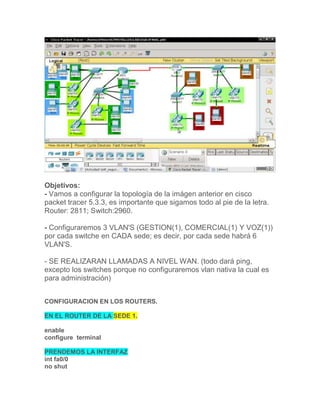
1. Objetivos:
- Vamos a configurar la topología de la imágen anterior en cisco
packet tracer 5.3.3, es importante que sigamos todo al pie de la letra.
Router: 2811; Switch:2960.
- Configuraremos 3 VLAN'S (GESTION(1), COMERCIAL(1) Y VOZ(1))
por cada switche en CADA sede; es decir, por cada sede habrá 6
VLAN'S.
- SE REALIZARAN LLAMADAS A NIVEL WAN. (todo dará ping,
excepto los switches porque no configuraremos vlan nativa la cual es
para administración)
CONFIGURACION EN LOS ROUTERS.
EN EL ROUTER DE LA SEDE 1.
enable
configure terminal
PRENDEMOS LA INTERFAZ
int fa0/0
no shut
2. exit
CREAMOS LAS SUBINTERFACES PARA CADA VLAN.
int fa0/0.30
encapsulation dot1Q 30
ip add 192.168.10.1 255.255.255.0
exit
int fa0/0.40
encapsulation dot1Q 40
ip add 192.168.20.1 255.255.255.0
exit
int fa0/0.50
encapsulation dot1Q 50
ip add 192.168.30.1 255.255.255.0
exit
HACEMOS LO MISMO CON LA OTRA INTERFAZ.
int fa0/1
no shut
exit
LA ENCAPSULACION.
int fa0/1.30
encapsulation dot1Q 30
ip add 192.168.40.1 255.255.255.0
exit
int fa0/1.40
encapsulation dot1Q 40
ip add 192.168.50.1 255.255.255.0
exit
int fa0/1.50
encapsulation dot1Q 50
ip add 192.168.60.1 255.255.255.0
exit
CREAMOS EL DHCP EN EL ROUTER SEDE 1.
ip dhcp excluded-address 192.168.10.1
ip dhcp pool GESTION
network 192.168.10.0 255.255.255.0
default-router 192.168.10.1
option 150 ip 192.168.10.1
exit
ip dhcp excluded-address 192.168.20.1
ip dhcp pool COMERCIAL
network 192.168.20.0 255.255.255.0
default-router 192.168.20.1
option 150 ip 192.168.20.1
3. exit
ip dhcp excluded-address 192.168.30.1
ip dhcp pool VOZ
network 192.168.30.0 255.255.255.0
default-router 192.168.30.1
option 150 ip 192.168.30.1
exit
ip dhcp excluded-address 192.168.40.1
ip dhcp pool GESTION2
network 192.168.40.0 255.255.255.0
default-router 192.168.40.1
option 150 ip 192.168.40.1
exit
ip dhcp excluded-address 192.168.50.1
ip dhcp pool COMERCIAL2
network 192.168.50.0 255.255.255.0
default-router 192.168.50.1
option 150 ip 192.168.50.1
exit
ip dhcp excluded-address 192.168.60.1
ip dhcp pool VOZ2
network 192.168.60.0 255.255.255.0
default-router 192.168.60.1
option 150 ip 192.168.60.1
exit
REALIZAMOS LA CONFIGURACIÓN DE LOS TELEFONOS IP ROUTER SEDE
1.
telephony-service
max-dn 5
max-ephones 5
ip source-address 192.168.30.1 port 2000 (GATEWAY VLAN VOZ)
ip source-address 192.168.60.1 port 2000 (GATEWAY VLAN VOZ1)
auto assign 1 to 5
ephone-dn 1
number 54001
exit
ephone-dn 2
number 54002
exit
ephone-dn 3
number 54003
exit
ephone-dn 4
number 54004
4. exit
exit
wr (GUARDAMOS)
exit
CONFIGURACION EN EL SWITCHES SEDE-1.
en
config ter
vlan 30
name GESTION
exit
vlan 40
name COMERCIAL
exit
vlan 50
name VOZ
exit
int fa0/1
switchport mode access
switchport access vlan 30
exit
int range f0/2-f0/3
switchport mode access
switchport access vlan 40
exit
int f0/4
switchport mode access
switchport acces vlan 30
switchport voice vlan 50
spanning-tree portfast
exit
int f0/5
switchport mode access
switchport acces vlan 40
switchport voice vlan 50
spanning-tree portfast
exit
int f0/24
switchport mode trunk
switchport trunk allowed vlan 30-50
exit
exit
exit
5. SEGUNDO SWITCH..
en
config ter
vlan 30
name GESTION2
exit
vlan 40
name COMERCIAL2
exit
vlan 50
name VOZ2
exit
int fa0/1
switchport mode access
switchport access vlan 30
exit
int range f0/2-f0/3
switchport mode access
switchport access vlan 40
exit
int range f0/4-f0/5
switchport mode access
switchport acces vlan 30
switchport voice vlan 50
spanning-tree portfast
exit
int f0/24
switchport mode trunk
switchport trunk allowed vlan 30-50
exit
exit
exit
REALIZAREMOS LA CONFIGURACION PARA EL ROUTER SEDE 2.
enable
configure terminal
PRENDEMOS LA INTERFAZ
int fa0/0
no shut
exit
CREAMOS LAS SUBINTERFACES PARA CADA VLAN, ESTO ES PARA QUE
SE PUEDA HACER PING ENTRE ELLAS.
6. int fa0/0.60
encapsulation dot1Q 60
ip add 192.170.10.1 255.255.255.0
exit
int fa0/0.70
encapsulation dot1Q 70
ip add 192.170.20.1 255.255.255.0
exit
int fa0/0.80
encapsulation dot1Q 80
ip add 192.170.30.1 255.255.255.0
exit
HACEMOS LO MISMO CON LA OTRA INTERFAZ
int fa0/1
no shut
exit
LAS SUBINTERFACES.
int fa0/1.60
encapsulation dot1Q 60
ip add 192.170.40.1 255.255.255.0
exit
int fa0/1.70
encapsulation dot1Q 70
ip add 192.170.50.1 255.255.255.0
exit
int fa0/1.80
encapsulation dot1Q 80
ip add 192.170.60.1 255.255.255.0
exit
CREAMOS EL DHCP..
ip dhcp excluded-address 192.170.10.1
ip dhcp pool GESTION
network 192.170.10.0 255.255.255.0
default-router 192.170.10.1
option 150 ip 192.170.10.1
exit
ip dhcp excluded-address 192.170.20.1
ip dhcp pool COMERCIAL
network 192.170.20.0 255.255.255.0
default-router 192.170.20.1
option 150 ip 192.170.20.1
exit
ip dhcp excluded-address 192.170.30.1
ip dhcp pool VOZ
7. network 192.170.30.0 255.255.255.0
default-router 192.170.30.1
option 150 ip 192.170.30.1
exit
ip dhcp excluded-address 192.170.40.1
ip dhcp pool GESTION2
network 192.170.40.0 255.255.255.0
default-router 192.170.40.1
option 150 ip 192.170.40.1
exit
ip dhcp excluded-address 192.170.50.1
ip dhcp pool COMERCIAL2
network 192.170.50.0 255.255.255.0
default-router 192.170.50.1
option 150 ip 192.170.50.1
exit
ip dhcp excluded-address 192.170.60.1
ip dhcp pool VOZ2
network 192.170.60.0 255.255.255.0
default-router 192.170.60.1
option 150 ip 192.170.60.1
exit
CONFIGURACION PARA LOS TELEFONOS IP
telephony-service
max-dn 5
max-ephones 5
ip source-address 192.170.30.1 port 2000 (GATEWAY DE LA VLAN DE VOZ)
ip source-address 192.170.60.1 port 2000 (GATEWAY DE LA VLAN DE VOZ1)
auto assign 1 to 5
ephone-dn 1
number 54005
exit
ephone-dn 2
number 54006
exit
ephone-dn 3
number 54007
exit
ephone-dn 4
number 54008
exit
8. exit
wr (GUARDAMOS)
exit
CONFIGURACION SWITCHES SEDE 2.
en
config ter
vlan 60
name GESTION
exit
vlan 70
name VOZ
exit
vlan 80
name COMERCIAL
exit
int fa0/1
switchport mode access
switchport access vlan 60
exit
int f0/2
switchport mode access
switchport voice vlan 70
spanning-tree portfast
exit
int f0/3
switchport mode access
switchport acces vlan 80
switchport voice vlan 70
spanning-tree portfast
exit
int f0/24
switchport mode trunk
switchport trunk allowed vlan 60-80
exit
exit
exit
SEGUNDO SWITCH..
en
config ter
vlan 60
name GESTION2
10. Network 192.170.40.0 0.0.0.255
Network 192.170.50.0 0.0.0.255
Network 192.170.60.0 0.0.0.255
Network 200.150.0.0 0.0.0.3
CONFIGURACION DE LOS TELEFONOS A NIVEL WAN
configuracion CME
ROUTER SEDE 1 (INTERFAZ DEL SERIAL 200.150.0.1)
dial-peer voice 1 voip
destination-pattern 5400. (EL PUNTO AL FINAL ES IMPORTANTE)
session target ipv4:200.150.0.2 (AQUI VA LA IP DE LA INTERFAZ WAN DEL
ROUTER DE LAS SEDE 2)
exit
ROUTER SEDE 2 (INTERFAZ DEL SERIAL 200.150.0.2)
dial-peer voice 1 voip
destination-pattern 5400. (EL PUNTO AL FINAL ES IMPORTANTE)
session target ipv4:200.150.0.1 (AQUI VA LA IP DE LA INTERFAZ WAN DEL
ROUTER DE LAS SEDE 1)
exit
PRUEBA!!!