Manual de taller de T. Oruga CATERPILLAR D7G
•
51 likes•19,829 views

This technical manual provides repair parts and special tools lists for Caterpillar Model D7G tractors. It contains information for performing unit, direct support, general support and depot level maintenance. The manual includes parts lists for the engine, fuel system, exhaust system, cooling system, electrical system, transmission and other components. It also covers a Service Life Extension Program that has been implemented on some D7G tractors.

Recommended
More Related Content
What's hot
What's hot (20)
Viewers also liked
Viewers also liked (19)
Similar to Manual de taller de T. Oruga CATERPILLAR D7G
Similar to Manual de taller de T. Oruga CATERPILLAR D7G (20)
More from ING. JUAN JOSE NINA CHARAJA
More from ING. JUAN JOSE NINA CHARAJA (20)
Recently uploaded
Recently uploaded (20)
Manual de taller de T. Oruga CATERPILLAR D7G
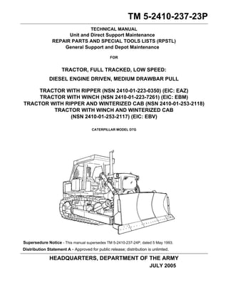
- 1. TM 5-2410-237-23P TECHNICAL MANUAL Unit and Direct Support Maintenance REPAIR PARTS AND SPECIAL TOOLS LISTS (RPSTL) General Support and Depot Maintenance FOR TRACTOR, FULL TRACKED, LOW SPEED: DIESEL ENGINE DRIVEN, MEDIUM DRAWBAR PULL TRACTOR WITH RIPPER (NSN 2410-01-223-0350) (EIC: EAZ) TRACTOR WITH WINCH (NSN 2410-01-223-7261) (EIC: EBM) TRACTOR WITH RIPPER AND WINTERIZED CAB (NSN 2410-01-253-2118) TRACTOR WITH WINCH AND WINTERIZED CAB (NSN 2410-01-253-2117) (EIC: EBV) CATERPILLAR MODEL D7G Supersedure Notice - This manual supersedes TM 5-2410-237-24P, dated 5 May 1993. Distribution Statement A - Approved for public release; distribution is unlimted. HEADQUARTERS, DEPARTMENT OF THE ARMY JULY 2005
- 2. This page Intentionally Left Blank. This page is blank.
- 3. TM 5-2410-237-23P C1 1 HEADQUARTERS TM 5-2410-237-23P DEPARTMENT OF THE ARMY Change No. 1 Washington, D.C., 30 July 2006 Unit and Direct Support Maintenance REPAIR PARTS AND SPECIAL TOOLS LISTS (RPSTL) General Support and Depot Maintenance FOR TRACTOR, FULL TRACKED, LOW SPEED: DIESEL ENGINE DRIVEN, MEDIUM DRAWBAR PULL TRACTOR WITH RIPPER (NSN 2410-01-223-0350) (EIC: EAZ) TRACTOR WITH WINCH (NSN 2410-01-223-7261) (EIC: EBM) TRACTOR WITH RIPPER AND WINTERIZED CAB (NSN 2410-01-253-2118) TRACTOR WITH WINCH AND WINTERIZED CAB (NSN 2410-01-253-2117) (EIC: EBV) CATERPILLAR MODEL D7G TM 5-2410-237-23P, dated 15 July 2005, is updated as follows: 1. A Service Life Extension Program (SLEP) has been implemented on selected D7G Tractors. SLEP infor-mation is included in this change package. 2. File this change sheet in front of the publication for reference purposes. 3. New or changed material is indicated by a vertical bar adjacent to the material and/or change designations at the bottom of the affected page. 4. Remove old pages and insert new pages: Remove Pages Insert Pages A and B A and B vii thru x vii thru x 185-1 thru Figure 188 185-1 thru Figure 188 Figure 192 thru Figure 195 Figure 192 thru Figure 195 200-1 thru Figure 201 200-1 thru Figure 201 203-1 thru Figure 204 203-1 thru Figure 204 205-1 thru Figure 206 205-1 thru Figure 206 207-1 thru Figure 208 207-1 thru Figure 208 I-1 thru I-176 I-1 thru 176 Distribution Statement A - Approved for public release; distribution is unlimited.
- 4. TM 5-2410-237-23P C1 By Order of the Secretary of the Army: PETER J. SCHOOMAKER General, United States Army Official: Chief of Staff JOYCE E. MORROW Administrative Assistant to the Secretary of the Army 0617906 DISTRIBUTION: To be distributed in accordance with the initial distribution number (IDN) 253608, requirements for TM 5-2410-237-23P.
- 5. TM 5-2410-237-23P LIST OF EFFECTIVE PAGES Dates of issue for original and change pages are: Original. . . . . . . . . . . . . 0 . . . . . . . . . . . 15 July 2005 Change 1 . . . . . . . . . . . 1 . . . . . . . . . . . 30 July 2006 TOTAL NUMBER OF PAGES IN THIS PUBLICATION IS 760 CONSISTING OF THE FOLLOWING: Page *Change No. No. Cover (Back Blank) 0 A (B Blank) 1 i thru vi 0 vii and x 1 0001 00-1 thru 0001 00-7 0 Figure 1 thru Figure 185 0 186 1 187 0 188 1 189 thru 191 0 192 thru 195 1 196 thru 199 0 200 1 201 thru 202 0 203 1 204 0 205 1 206 0 207A thru 207H 1 208 0 I-1 thru I-176 1 A/(B Blank)
- 7. TM 5-2410-237-23P TECHNICAL MANUAL HEADQUARTERS TM 5-2410-237-23P DEPARTMENT OF THE ARMY REPORTING ERRORS AND RECOMMENDING IMPROVEMENTS You can help improve this publication. If you find any mistakes or if you know of a way to improve the proce-dures, please let us know. Submit your DA Form 2028 (Recommended Changes to Equipment Technical Publications), through the Internet, on the Army Electronic Product Support (AEPS) website. The Internet address is http://aeps.ria.army.mil. If you need a password, scroll down and click on “ACCESS REQUEST FORM”. The DA Form 2028 is located in the ONLINE FORMS PROCESSING section of the AEPS. Fill out the form and click on SUBMIT. Using this form on the AEPS will enable us to respond quicker to your com-ments and better manage the DA Form 2028 program. You may also mail, fax or e-mail your letter, DA Form 2028 direct to: AMSTA-LC-LP/TECH PUBS, TACOM-RI, 1 Rock Island Arsenal, Rock Island, IL 61299-7630. The e-mail address is: TACOM-TECH-PUBS@ria.army.mil. The fax number is DSN 793-0726 or Commercial (309) 782-0726. i Washington, D.C., 15 July 2005 Unit and Direct Support Maintenance REPAIR PARTS AND SPECIAL TOOLS LISTS (RPSTL) General Support and Depot Maintenance FOR TRACTOR, FULL TRACKED, LOW SPEED: DIESEL ENGINE DRIVEN, MEDIUM DRAWBAR PULL TRACTOR WITH RIPPER (NSN 2410-01-223-0350) (EIC: EAZ) TRACTOR WITH WINCH (NSN 2410-01-223-7261) (EIC: EBM) TRACTOR WITH RIPPER AND WINTERIZED CAB (NSN 2410-01-253-2118) TRACTOR WITH WINCH AND WINTERIZED CAB (NSN 2410-01-253-2117) (EIC: EBV) CATERPILLAR MODEL D7G Current as of 17 December 2004 SUPERSEDURE NOTICE - This manual supersedes TM 5-2410-237-24P, dated 5 May 1993 DISTRIBUTION STATEMENT A - Approved for public release; distribution is unlimited. TABLE OF CONTENTS Illus/ Fig Page WP 0001 00 Introduction. . . . . . . . . . . . . . . . . . . . . . . . . . . . . . . . . . . . . . . . . . . . . . . . . . 0001 00-1 WP 0002 00 Repair Parts List GROUP 01 ENGINE 0100 ENGINE ASSEMBLY.................................................................................................. 1-1
- 8. TM 5-2410-237-23P TABLE OF CONTENTS (Con’t) ii Illus/ Fig Page ENGINE MOUNTING HARDWARE............................................................................ 1 1-1 ENGINE SUPPORT GROUP ..................................................................................... 2 2-1 0101 CRANKCASE, BLOCK, CYLINDER HEAD ................................................................ 3-1 CYLINDER BLOCK ASSEMBLY................................................................................ 3 3-1 CYLINDER HEAD GROUP ........................................................................................ 4 4-1 0102 CRANKSHAFT ........................................................................................................... 5-1 CRANKSHAFT GROUP ............................................................................................. 5 5-1 0103 FLYWHEEL ASSEMBLY............................................................................................ 6-1 FLYWHEEL AND FLYWHEEL HOUSING.................................................................. 6 6-1 0104 PISTONS, CONNECTING RODS .............................................................................. 7-1 PISTON AND ROD GROUP....................................................................................... 7 7-1 0105 VALVES, CAMSHAFTS, AND TIMING SYSTEM....................................................... 8-1 CAMSHAFT GROUP.................................................................................................. 8 8-1 VALVE MECHANISM AND VALVE COVER .............................................................. 9 9-1 FRONT COVER GROUP ........................................................................................... 10 10-1 TIMING GEAR GROUP.............................................................................................. 11 11-1 0106 ENGINE LUBRICATION SYSTEM............................................................................. 12-1 OIL PAN GROUP ....................................................................................................... 12 12-1 ENGINE OIL LINES GROUP...................................................................................... 13 13-1 ENGINE OIL PUMP GROUP...................................................................................... 14 14-1 ENGINE OIL COOLER ............................................................................................... 15 15-1 OIL FILLER, OIL LEVEL GAGE AND OIL FILTER..................................................... 16 16-1 CRANKCASE BREATHER......................................................................................... 17 17-1 OIL SAMPLING GROUP ............................................................................................ 18 18-1 DRAIN LINES ............................................................................................................. 19 19-1 0108 MANIFOLDS............................................................................................................... 20-1 EXHAUST MANIFOLD ............................................................................................... 20 20-1 0109 ACCESSORY DRIVING MECHANISMS.................................................................... 21-1 DRIVE REAR GEAR GROUP .................................................................................... 21 21-1 GROUP 03 FUEL SYSTEM 0301 CARBURETOR, FUEL INJECTOR ............................................................................ 22-1 FUEL INJECTOR NOZZLE ........................................................................................ 22 22-1 0302 FUEL PUMPS............................................................................................................. 23-1 FUEL INJECTOR LINES ............................................................................................ 23 23-1 FUEL PRIMING PUMP AND FILTER GROUP........................................................... 24 24-1 FUEL TRANSFER PUMP........................................................................................... 25 25-1 FUEL INJECTION PUMP AND GOVERNOR............................................................. 26 26-1 FUEL INJECTION PUMP ........................................................................................... 27 27-1 0304 AIR CLEANER............................................................................................................ 28-1 AIR CLEANER AND DUST EJECTOR....................................................................... 28 28-1
- 9. TM 5-2410-237-23P TABLE OF CONTENTS (Con’t) iii Illus/ Fig Page AIR LINES GROUP .................................................................................................... 29 29-1 AIR LINES GROUP - ENGINE ................................................................................... 30 30-1 0305 SUPERCHARGER, BLOWER, TURBOCHARGER OR ALTITUDE COMPENSATOR 31-1 TURBOCHARGER GROUP....................................................................................... 31 31-1 TURBOCHARGER OIL LINES ................................................................................... 32 32-1 0306 TANKS, LINES, FITTINGS, HEADERS...................................................................... 33-1 LEVER AND VALVE ASSEMBLY .............................................................................. 33 33-1 FUEL LINES ............................................................................................................... 34 34-1 FUEL TANK GROUP.................................................................................................. 35 35-1 0308 ENGINE SPEED GOVERNOR AND CONTROLS ..................................................... 36-1 GOVERNOR CONTROL GROUP .............................................................................. 36 36-1 FUEL RATIO CONTROL ............................................................................................ 37 37-1 0309 FUEL FILTERS........................................................................................................... 38-1 SECONDARY FUEL FILTER ..................................................................................... 38 38-1 0311 ENGINE STARTING AIDS ......................................................................................... 39-1 ETHER AID GROUP .................................................................................................. 39 39-1 GROUP 04 EXHAUST SYSTEM 0401 MUFFLER AND PIPES............................................................................................... 40-1 MUFFLER AND EXHAUST ........................................................................................ 40 40-1 GROUP 05 COOLING SYSTEM 0501 RADIATOR, EVAPORATIVE COOLER, OR HEAT EXCHANGER............................ 41-1 RADIATOR GROUP................................................................................................... 41 41-1 RADIATOR TANK ASSEMBLY (NON-SLEP AND SLEP).......................................... 42 42-1 0503 WATER MANIFOLD, HEADERS, THERMOSTATS, AND HOUSING GASKET........ 43-1 WATER TEMPERATURE HOUSING AND REGULATOR......................................... 43 43-1 0504 WATER PUMP ........................................................................................................... 44-1 WATER LINES GROUP ............................................................................................. 44 44-1 WATER PUMP ........................................................................................................... 45 45-1 0505 FAN ASSEMBLY ........................................................................................................ 46-1 FAN DRIVE................................................................................................................. 46 46-1 FAN GROUP .............................................................................................................. 47 47-1 GROUP 06 ELECTRICAL SYSTEM 0601 GENERATOR, ALTERNATOR................................................................................... 48-1 ALTERNATOR MOUNTING....................................................................................... 48 48-1 ALTERNATOR............................................................................................................ 49 49-1 0603 STARTING MOTOR ................................................................................................... 50-1 STARTER MOTOR MOUNTING GROUP.................................................................. 50 50-1 ELECTRIC STARTING MOTOR ................................................................................ 51 51-1 STARTER SOLENOID ............................................................................................... 52 52-1
- 10. TM 5-2410-237-23P TABLE OF CONTENTS (Con’t) iv Illus/ Fig Page 0607 INSTRUMENT OR ENGINE CONTROL PANEL........................................................ 53-1 ELECTRICAL GAGE GROUP.................................................................................... 53 53-1 WIRING HARNESS .................................................................................................... 54 54-1 STE/ICE WIRING ....................................................................................................... 55 55-1 DASH PANEL WIRING............................................................................................... 56 56-1 0608 MISCELLANEOUS ITEMS ......................................................................................... 57-1 SWITCHES................................................................................................................. 57 57-1 0609 LIGHTS....................................................................................................................... 58-1 LIGHTING GROUP..................................................................................................... 58 58-1 0610 SENDING UNITS AND WARNING SWITCHES......................................................... 59-1 TRANSMISSION CONTROL WIRING........................................................................ 59 59-1 0611 HORN, SIREN ............................................................................................................ 60-1 HORN AND BACK-UP ALARM .................................................................................. 60 60-1 0612 BATTERIES, STORAGE (WET OR DRY).................................................................. 61-1 BATTERIES AND CABLES ........................................................................................ 61 61-1 0613 HULL OR CHASSIS WIRING HARNESS................................................................... 62-1 CHASSIS WIRING MOUNTING GROUP................................................................... 62 62-1 WIRING LEADS AND FUSEHOLDERS..................................................................... 63 63-1 ENGINE WIRING HARNESS ..................................................................................... 64 64-1 STARTING RECEPTACLE......................................................................................... 65 65-1 WINTER CAB ELECTRICAL PACKAGE.................................................................... 66 66-1 GROUP 07 TRANSMISSION 0705 TRANSMISSION SHIFTING COMPONENTS............................................................ 67-1 TRANSMISSION CONTROL GROUP........................................................................ 67 67-1 TRANSMISSION CONTROL LINKAGE ..................................................................... 68 68-1 0708 TORQUE CONVERTER OR FLUID COUPLING ....................................................... 69-1 TORQUE DIVIDER GROUP....................................................................................... 69 69-1 TORQUE DIVIDER ASSEMBLY ................................................................................ 70 70-1 0710 TRANSMISSION ASSEMBLY .................................................................................... 71-1 TRANSMISSION ARRANGEMENT ........................................................................... 71 71-1 CARRIER AND CLUTCH HOUSINGS (NO. 2 AND 3)............................................... 72 72-1 PLANETARY TRANSMISSION .................................................................................. 73 73-1 PLANETARY TRANSMISSION, CARRIER AND CLUTCH HOUSINGS (NO. 4 AND 5) ............................................................................................................ 74 74-1 TRANSMISSION HYDRAULIC CONTROL................................................................ 75 75-1 SELECTOR VALVE.................................................................................................... 76 76-1 PRESSURE CONTROL VALVE................................................................................. 77 77-1 TRANSFER GEAR PUMP.......................................................................................... 78 78-1 0721 COOLERS, PUMPS, MOTORS.................................................................................. 79-1 TORQUE CONVERTER RELIEF VALVE................................................................... 79 79-1 TORQUE CONVERTER COOLER LINES ................................................................. 80 80-1 TORQUE DIVIDER SCAVENGE PUMP .................................................................... 81 81-1 UPPER POWER TRAIN LINES AND MOUNTING HARDWARE............................... 82 82-1 POWER TRAIN LINES GROUP................................................................................. 83 83-1
- 11. TM 5-2410-237-23P TABLE OF CONTENTS (Con’t) v Illus/ Fig Page TRANSMISSION OIL COOLER ................................................................................. 84 84-1 TRANSMISSION AND STEERING CLUTCH FILTER................................................ 85 85-1 MAGNETIC SCREEN GROUP................................................................................... 86 86-1 RELIEF VALVE GROUP ............................................................................................ 87 87-1 TRANSMISSION OIL PUMP ...................................................................................... 88 88-1 TRANSMISSION OIL SAMPLING VALVE ................................................................. 89 89-1 GROUP 08 TRANSFER AND FINAL DRIVE ASSEMBLIES 0801 POWER TRANSFER AND FINAL DRIVE ASSEMBLIES .......................................... 90-1 FINAL DRIVE SPROCKET, SUPPORT AND CASE .................................................. 90 90-1 FINAL DRIVE PINION, CAGE, AND SHAFT.............................................................. 91 91-1 GROUP 09 PROPELLER, PROPELLER SHAFTS, UNIVERSAL JOINTS, COUPLER AND CLAMP ASSEMBLY 0900 PROPELLER SHAFTS............................................................................................... 92-1 DRIVE SHAFT ............................................................................................................ 92 92-1 GROUP 13 WHEELS AND TRACKS 1301 SUSPENSION ASSEMBLY........................................................................................ 93-1 EQUALIZER BAR ....................................................................................................... 93 93-1 TRACK ROLLER FRAME........................................................................................... 94 94-1 1302 TRACK SUPPORT ROLLERS AND BRACKETS....................................................... 95-1 TRACK CARRIER ROLLER....................................................................................... 95 95-1 SINGLE FLANGE TRACK ROLLER........................................................................... 96 96-1 DOUBLE FLANGE TRACK ROLLER ......................................................................... 97 97-1 1303 TRACK IDLERS AND BRACKETS............................................................................. 98-1 FRONT IDLER SPRING ROD AND CYLINDER ........................................................ 98 98-1 FRONT IDLER COLLAR AND BEARINGS ................................................................ 99 99-1 1305 TRACK ASSEMBLY ................................................................................................... 100-1 TRACK GROUP (20-INCH) ........................................................................................ 100 100-1 GROUP 14 STEERING 1403 STEERING BRAKES.................................................................................................. 101-1 BRAKE HYDRAULIC CONTROL AND LINES AND FITTINGS ................................. 101 101-1 RIGHT HAND BRAKE HYDRAUILC CONTROL HOUSING ...................................... 102 102-1 BRAKE LINKAGE ....................................................................................................... 103 103-1 BRAKE PEDAL LINKAGE .......................................................................................... 104 104-1 BRAKE ACTUATING MECHANISM........................................................................... 105 105-1 STEERING CONTROL VALVE LINES AND LINKAGE.............................................. 106 106-1 STEERING CLUTCH CONTROL LEVER LINKAGE.................................................. 107 107-1 STEERING CLUTCH.................................................................................................. 108 108-1 1414 STEERING SYSTEM VALVES................................................................................... 109-1 STEERING CLUTCH CONTROL VALVE................................................................... 109 109-1 GROUP 15 FRAME, TOWING ATTACHMENTS, DRAWBARS, AND ARTICULATION SYSTEMS 1501 FRAME ASSEMBLY................................................................................................... 110-1 FRAME AND CASE.................................................................................................... 110 110-1
- 12. TM 5-2410-237-23P TABLE OF CONTENTS (Con’t) vi Illus/ Fig Page GROUP 18 BODY, CAB, HOOD, AND HULL 1801 BODY, CAB, HOOD, AND HULL ASSEMBLIES........................................................ 111-1 CRANKCASE GUARD ............................................................................................... 111 111-1 RADIATOR GUARD ................................................................................................... 112 112-1 RECOIL MECHANISM GUARD ................................................................................. 113 113-1 TRACK ROLLER GUARD .......................................................................................... 114 114-1 HOOD AND DISH PANEL .......................................................................................... 115 115-1 ROPS MOUNTING ..................................................................................................... 116 116-1 PROTECTIVE SCREEN............................................................................................. 117 117-1 WINTERIZED CAB AND FRONT SECTION .............................................................. 118 118-1 WINTERIZED CAB, RIGHT HAND SIDE ................................................................... 119 119-1 WINTERIZED CAB, LEFT HAND SIDE...................................................................... 120 120-1 WINTERIZED CAB - REAR........................................................................................ 121 121-1 CAB NOISE CONTROL COMPONENTS................................................................... 122 122-1 HYDRAULIC TANK MOUNTING................................................................................ 123 123-1 1802 FENDERS, RUNNING BOARDS WITH MOUNTING AND ATTACHING PARTS, OUTRIGGERS, WINDSHIELD, GLASS, ETC. ........................................................... 124-1 FENDER GROUP....................................................................................................... 124 124-1 1805 FLOORS, SUBFLOORS AND RELATED COMPONENTS........................................ 125-1 FLOOR PLATES......................................................................................................... 125 125-1 1806 UPHOLSTERY, SEATS, AND CARPETS .................................................................. 126-1 ADJUSTABLE SEAT GROUP .................................................................................... 126 126-1 SEAT GROUP ............................................................................................................ 127 127-1 SEAT FRAME............................................................................................................. 128 128-1 1808 STOWAGE RACKS, BOXES, STRAPS, CARRYING CASES, CABLE REELS, HOSE REELS, ETC.................................................................................................... 129-1 TOOL BOX ................................................................................................................. 129 129-1 DECONTAMINATION MOUNTING BRACKET .......................................................... 130 130-1 GROUP 20 HOIST, WINCH, CAPSTAN, WINDLASS, POWER CONTROL UNIT AND POWER TAKE-OFF 2001 HOIST, CAPSTAN, WINDLESS, CRANE, OR WINCH ASSEMBLY.......................... 131-1 WINCH AND MOUNTING HARDWARE..................................................................... 131 131-1 CABLE GUIDE AND CASE GROUP .......................................................................... 132 132-1 WINCH CONTROL VALVE TUBING.......................................................................... 133 133-1 WINCH GROUP - COVER ASSEMBLY..................................................................... 134 134-1 SHAFT AND DRUM ASSEMBLY ............................................................................... 135 135-1 DISC AND HUB ASSEMBLY...................................................................................... 136 136-1 GEAR ASSEMBLY ..................................................................................................... 137 137-1 WINCH BREATHER, WINCH MAGNETIC SCREEN AND WINCH ASSEMBLY (PARTIAL) .............................................................................................. 138 138-1 DISC ASSEMBLY....................................................................................................... 139 139-1 WINCH OIL FILTER ................................................................................................... 140 140-1 WINCH INPUT SHAFT ............................................................................................... 141 141-1 WINCH CONTROLS................................................................................................... 142 142-1 WINCH OIL PUMP GROUP ....................................................................................... 143 143-1 GROUP 22 BODY, CHASSIS AND HULL, AND ACCESSORY ITEMS 2202 ACCESSORY ITEMS ................................................................................................. 144-1 MIRROR GROUP ....................................................................................................... 144 144-1
- 13. TM 5-2410-237-23P TABLE OF CONTENTS (Con’t) vii Illus/ Fig Page 2207 WINTERIZATION EQUIPMENT ................................................................................. 145-1 FRONT AND REAR DEFROSTER FAN..................................................................... 145 145-1 FRONT AND REAR WIPER MOTORS ...................................................................... 146 146-1 24 VOLT HEATER ASSEMBLY ................................................................................. 147 147-1 2210 DATA PLATES AND INSTRUCTION HOLDERS....................................................... 148-1 PLATES, FILM, TAGS, AND STENCILS.................................................................... 148 148-1 GROUP 24 HYDRAULIC AND FLUID SYSTEMS 2401 HYDRAULIC PUMP.................................................................................................... 149-1 HYDRAULIC PUMP GROUP ..................................................................................... 149 149-1 2402 MANIFOLD AND/OR CONTROL VALVES................................................................. 150-1 WINCH CONTROL VALVE GROUP .......................................................................... 150 150-1 PRESSURE VALVE ................................................................................................... 151 151-1 BODY ASSEMBLY ..................................................................................................... 152 152-1 CONTROL VALVE GROUP ....................................................................................... 153 153-1 TILT CONTROL PILOT VALVE GROUP, WITHOUT RIPPER................................... 154 154-1 VALVE GROUP WITH RIPPER ................................................................................. 155 155-1 RIPPER CONTROL VALVE ....................................................................................... 156 156-1 PRESSURE CONTROL VALVE................................................................................. 157 157-1 BLADE LIFT AND TILT CONTROL VALVE ............................................................... 158 158-1 BLADE LIFT AND TILT CONTROL VALVE ............................................................... 159 159-1 VALVE GROUP (QUICK DROP) (LEFT HAND AND RIGHT HAND)......................... 160 160-1 2403 HYDRAULIC CONTROL AND/OR MANUAL CONTROLS......................................... 161-1 CONTROL LINKAGE - DOZER TILT ......................................................................... 161 161-1 CONTROL LINKAGE - RIPPER ................................................................................. 162 162-1 2404 TILT CYLINDERS AND TILT CRANK ........................................................................ 163-1 TILT CYLINDER ......................................................................................................... 163 163-1 2406 STRAINERS, FILTERS, LINES AND FITTINGS, ETC............................................... 164-1 PUMP LINES GROUP................................................................................................ 164 164-1 PUMP LINES GROUP................................................................................................ 165 165-1 BULLDOZER LINES GROUP..................................................................................... 166 166-1 BLADE LIFT AND TILT HOSE AND RELATED PARTS ............................................ 167 167-1 HYDRAULIC TILT CYLINDER LINES GROUP.......................................................... 168 168-1 TILT CYLINDER LINES GROUP................................................................................ 169 169-1 RIPPER LINES GROUP - SIDE ................................................................................. 170 170-1 RIPPER LINES GROUP - FRONT ............................................................................. 171 171-1 RIPPER LINES GROUP............................................................................................. 172 172-1 WINCH LINES GROUP .............................................................................................. 173 173-1 2407 HYDRAULIC CYLINDERS ......................................................................................... 174-1 CYLINDER AND VALVE GROUP (RIGHT HAND)..................................................... 174 174-1 CYLINDER AND VALVE GROUP (LEFT HAND)....................................................... 175 175-1 BLADE LIFT CYLINDER (RIGHT HAND AND LEFT HAND) ..................................... 176 176-1 BLADE LIFT CYLINDER MOUNTING TUBE ............................................................. 177 177-1 RIPPER LIFT CYLINDER GROUP............................................................................. 178 178-1 2408 LIQUID TANKS OR RESERVOIRS............................................................................ 179-1 HYDRAULIC TANK VALVE GROUP.......................................................................... 179 179-1 HYDRAULIC TANK GROUP ...................................................................................... 180 180-1
- 14. TM 5-2410-237-23P TABLE OF CONTENTS (Con’t) Change 1 viii Illus/ Fig Page HYDRAULIC TANK FILTER GROUP......................................................................... 181 181-1 GROUP 33 SPECIAL PURPOSE KITS 3307 SPECIAL PURPOSE KITS ......................................................................................... 182-1 MINE RAKE (1991 MCAP) ......................................................................................... 182 182-1 MINE RAKE (1991 MCAP) ......................................................................................... 183 183-1 MINE RAKE (1996 AND 2004 MCAP)........................................................................ 184 184-1 MINE RAKE (1996 AND 2004 MCAP)........................................................................ 185 185-1 CYLINDER GUARD.................................................................................................... 186 186-1 RADIATOR GUARD GROUP..................................................................................... 187 187-1 RIGHT SIDE ENGINE GUARDS (1991 AND 1996 MCAP)........................................ 188 188-1 LEFT AND RIGHT SIDE ENGINE GUARDS.............................................................. 189 189-1 LEFT SIDE ENGINE GUARD (1991 and 1996 MCAP) .............................................. 190 190-1 ENGINE HOOD GUARDS.......................................................................................... 191 191-1 FRONT OF CAB ......................................................................................................... 192 192-1 TOP AND REAR OF CAB .......................................................................................... 193 193-1 LEFT SIDE OF CAB ................................................................................................... 194 194-1 INSIDE FRAME SUPPORT........................................................................................ 195 195-1 INSIDE FRONT CAB .................................................................................................. 196 196-1 INSIDE OF CAB ......................................................................................................... 197 197-1 DOOR LATCH GROUP .............................................................................................. 198 198-1 FRONT CAB VENT .................................................................................................... 199 199-1 WINDOW GROUP...................................................................................................... 200 200-1 RECIRCULATING FAN AND RELATED PARTS ....................................................... 201 201-1 FRESH AIR FAN (REAR) ........................................................................................... 202 202-1 REAR CAB GUARDS ................................................................................................. 203 203-1 LEFT SIDE BATTERY BOX COVER.......................................................................... 204 204-1 HYDRAULIC TANK COVERING ................................................................................ 205 205-1 RIGHT REAR SIDE OF CAB...................................................................................... 206 206-1 REAR BOTTOM GUARD ........................................................................................... 207 207-1 BREATHER TUBE AND AUXILIARY DRIVE ASSEMBLY......................................... 207A 207A-1 OIL LEVEL GAGE GUIDE TUBE ASSEMBLY ........................................................... 207B 207B-1 COMPRESSOR ASSEMBLY ..................................................................................... 207C 207C-1 HARNESS ASSEMBLIES........................................................................................... 207D 207D-1 AIR CONDITIONER ASSEMBLY ............................................................................... 207E 207E-1 GUARD ASSEMBLY .................................................................................................. 207F 207F-1 AIR CONDITIONER LINES ........................................................................................ 207G 207G-1 AIR CONDITIONER ASSEMBLY ............................................................................... 207H 207H-1 GROUP 47 GAGES (NON-ELECTRICAL) WEIGHING AND MEASURING DEVICES 4701 INSTRUMENTS (SPEED AND DISTANCE)............................................................... 208-1 TACHOMETER DRIVE GROUP ................................................................................ 208 208-1 4702 GAGES, MOUNTINGS, LINES AND FITTINGS......................................................... 209-1 GAGE GROUP ........................................................................................................... 209 209-1 GROUP 74 CRANES, SHOVELS, AND EARTH MOVING EQUIPMENT COMPONENTS 7435 MOLDBOARD ASSEMBLY ........................................................................................ 210-1 BLADE GROUP.......................................................................................................... 210 210-1 7436 LIFT ARMS AND PIVOT ASSEMBLIES..................................................................... 211-1 PUSH ARM GROUP AND TRUNNION GROUP........................................................ 211 211-1
- 15. TM 5-2410-237-23P TABLE OF CONTENTS (Con’t) Illus/ Fig Page 7465 ROOTERS, RIPPERS, PLOWS, HARROWS, AND ROTARY TILLERS ................... 212-1 RIPPER GROUP ........................................................................................................ 212 212-1 RIPPER MOUNTING GROUP.................................................................................... 213 213-1 RIPPER TOOTH GROUP........................................................................................... 214 214-1 ix Change 1 GROUP 94 REPAIR KITS AND SETS 9401 REPAIR KITS ............................................................................................................. KITS-1 KITS............................................................................................................................ KITS KITS-1 GROUP 95 GENERAL USE STANDARIZED PARTS 9501 BULK MATERIEL ....................................................................................................... BULK-1 BULK MATERIEL ....................................................................................................... BULK BULK-1 WP 0003 00 Special Tools GROUP 26 TOOLS AND TEST EQUIPMENT 2604 SPECIAL TOOLS ....................................................................................................... 215-1 SPECIAL TOOLS, UNIT SUPPORT .......................................................................... 215 215-1 SPECIAL TOOLS, DIRECT SUPPORT ..................................................................... 216 216-1 SPECIAL TOOLS, GENERAL SUPPORT ................................................................. 217 217-1 WP 0004 00 Cross-Reference Indexes NATIONAL STOCK NUMBER INDEX........................................................................ I-1 PART NUMBER INDEX.............................................................................................. I-56
- 17. TM 5-2410-237-23P FIELD MAINTENANCE (UNIT AND DIRECT SUPPORT MAINTENANCE) REPAIR PARTS AND SPECIAL TOOLS LISTS (RPSTL) ALSO INCLUDES SUSTAINMENT MAINTENANCE (GENERAL SUPPORT AND DEPOT MAINTENANCE) INTRODUCTION 0001 00 SCOPE 1. This RPSTL lists and authorizes spares and repair parts; special tools; special test, measurement, and diagnostic equip-ment (TMDE); and other special support equipment required for performance of Field and Sustainment level mainte-nance of the Tractor, Full Tracked. The D7G model is covered in this manual. Unless otherwise noted, the illustrations and corresponding parts listing applies to this model. It authorizes the requisitioning, issue, and disposition of spares, repair parts, and special tools as indicated by the source, maintenance, and recoverability (SMR) codes. 2. A Service Life Extension Program (SLEP) has been implemented on the D7G Tractor. GENERAL In addition to the Introduction work package, this RPSTL is divided into the following work packages: a. Repair Parts Lists Work Package. Work package containing lists of spares and repair parts authorized by this RPSTL for use in the performance of maintenance. This work package also includes parts which must be removed for replacement of the authorized parts. Parts lists are composed of functional groups in ascending alphanumeric sequence, with the parts in each group listed in ascending figure and item number sequence. Sending units, brack-ets, filters, and bolts are listed with the component they mount on. Bulk materials are listed by item name in FIG. BULK at the end of the work package. Repair parts kits are listed separately in their own functional group. Items listed are shown on the associated illustrations. b. Special Tools List Work Package. Work package containing lists of special tools, special TMDE, and special support equipment authorized by this RPSTL [as indicated by Basis of Issue (BOI) information in the DESCRIP-TION AND USABLE ON CODE (UOC) column]. Tools that are components of common tool sets and/or Class SOURCE CODE MAINTENANCE CODE RECOVERABILITY CODE XXxxx xxXXx xxxxX 1st two positions 3rd position 4th position 5th position How you get an item. Who can install, replace or Who can do complete repair* on the item. 0001 00-1 VII are listed. c. Cross-Reference Indexes Work Package. There are two cross-reference indexes in this RPSTL: National Stock Number Index and Part Number Index. EXPLANATION OF COLUMNS IN THE REPAIR PARTS LISTS AND SPECIAL TOOLS LIST WORK PACKAGES a. Item No. (Column 1). Indicates the number used to identify items called out in the illustration. b. SMR Code (Column 2). The SMR code containing supply/requisitioning information, maintenance level authori-zation criteria, and disposition instruction, as shown in the following breakout: use the item. Who determines disposition action on an unserviceable item. * Complete Repair: Maintenance capacity, capability, and authority to perform all corrective maintenance tasks of the “Repair” function in a use/user environment in order to restore serviceability to a failed item.
- 18. TM 5-2410-237-23P FIELD MAINTENANCE (UNIT AND DIRECT SUPPORT MAINTENANCE) REPAIR PARTS AND SPECIAL TOOLS LISTS (RPSTL) ALSO INCLUDES SUSTAINMENT MAINTENANCE (GENERAL SUPPORT AND DEPOT MAINTENANCE INTRODUCTION - CONTINUED 0001 00 EXPLANATION OF COLUMNS IN THE REPAIR PARTS LISTS AND SPECIAL TOOLS LIST WORK PACKAGES - CONTINUED (1) Source Code. The source code tells you how to get an item needed for maintenance, repair, or overhaul of an end item/equipment. Explanations of source codes follow: Code Application/Explanation NOTE Cannibalization of controlled exchange, when authorized, may be used as a source of supply for items with the above source codes, except for those source coded “XA” or those aircraft support items restricted by requirements of AR 750-1. 0001 00-2 PA PB PC PD PE PF PG Stocked items; use the applicable NSN to request/requisition items with these source codes. They are authorized to the maintenance category indicated by the code entered in the third position of the SMR code. Items coded PC are subject to deterioration. . . . . . . . . . . . . . . . . . . . . . . . . . . . . . . . . . . . . . . . . . . . . . . . . . . . . . . . . . . . . . . . . . . KD KF KB Items with these codes are not to be requested/requisitioned individually. They are part of a kit which is authorized to the maintenance level indicated in the third posi-tion of the SMR code. The complete kit must be requisitioned and applied. . . . . . . . . . . . . . . . . . . . . . . . . . . . . . . . . . . . . . . . . . . . . . . . . . . . . . . . . . . . . . . . . . . MO - Made at Unit/ AVUM level MF - Made at DS/AVIM Level MH - Made at GS Level ML - Made at SRA MD - Made at Depot Items with these codes are not to be requested/requisitioned individually. They must be made from bulk materiel which is identified by the part number in the DESCRIPTION AND USABLE ON CODE (UOC) column and listed in the bulk materiel group work package of the RPSTL. If the item is authorized to you by the third position of the SMR code, but the source code indicates it is made at a higher level, order the item from the higher level of maintenance. . . . . . . . . . . . . . . . . . . . . . . . . . . . . . . . . . . . . . . . . . . . . . . . . . . . . . . . . . . . . . . . . . . AO-Assembled by Unit/ AVUM level AF-Assembled by DS/ AVIM level AH-Assembled by GS level AL-Assembled by SRA AD-Assembled by Depot Items with these codes are not to be requested/requisitioned individually. The parts that make up the assembled item must be requisitioned or fabricated and assembled at the level of maintenance indicated by the source code. If the third position of the SMR code authorizes you to replace the item, but the source code indicates the item is assembled at a higher level, order the item from the higher level of maintenance. XA XB XC XD Do not requisition an “XA” coded item. Order the next higher assembly. (Refer to NOTE below). If an item is not available from salvage, order it using the CAGEC and P/N. Installation drawings, diagrams, instruction sheets, field service drawings; identi-fied by manufacturer’s P/N. Item is not stocked. Order an XD-coded item through normal supply channels using the CAGEC and P/N given, if no NSN is available.
- 19. TM 5-2410-237-23P FIELD MAINTENANCE (UNIT AND DIRECT SUPPORT MAINTENANCE) REPAIR PARTS AND SPECIAL TOOLS LISTS (RPSTL) ALSO INCLUDES SUSTAINMENT MAINTENANCE (GENERAL SUPPORT AND DEPOT MAINTENANCE INTRODUCTION - CONTINUED 0001 00 EXPLANATION OF COLUMNS IN THE REPAIR PARTS LISTS AND SPECIAL TOOLS LIST WORK PACKAGES - CONTINUED (2) Maintenance Code. Maintenance codes tell you the level(s) of maintenance authorized to use and repair support items. The maintenance codes are entered in the third and fourth positions of the SMR code as fol-lows: (a) Third Position. The maintenance code entered in the third position tells you the lowest maintenance level authorized to remove, replace, and use an item. The maintenance code entered in the third posi-tion will indicate authorization to one of the following levels of maintenance: Code Application/Explanation C. . . . . . . . . . . . . . . . .Crew or Operator maintenance done within Unit/AVUM maintenance. O . . . . . . . . . . . . . . . .Unit Level/AVUM maintenance can remove, replace, and use the item. F. . . . . . . . . . . . . . . . .Direct Support/AVIM maintenance can remove, replace, and use the item. H . . . . . . . . . . . . . . . .General Support maintenance can remove, replace, and use the item. L . . . . . . . . . . . . . . . .Specialized Repair Activity (SRA) can remove, replace, and use the item. D . . . . . . . . . . . . . . . .Depot Maintenance can remove, replace, and use the item. (b) Fourth Position. The maintenance code entered in the fourth position tells you whether or not the item is to be repaired and identifies the lowest maintenance level with the capability to do complete repair (perform all authorized repair functions). NOTE Some limited repair may be done on the item at a lower level of maintenance, if authorized by the Mainte-nance Allocation Chart (MAC) and SMR codes. Code Application/Explanation O . . . . . . . . . . . . . . . .Unit/AVUM is the lowest level that can do complete repair of the item. F. . . . . . . . . . . . . . . . .Direct Support/AVIM is the lowest level that can do complete repair of the item. H . . . . . . . . . . . . . . . .General Support is the lowest level that can do complete repair of the item. L. . . . . . . . . . . . . . . . .Specialized Repair Activity (SRA) is the lowest level that can do complete repair 0001 00-3 of the item. D . . . . . . . . . . . . . . . .Depot is the lowest level that can do complete repair of the item. Z. . . . . . . . . . . . . . . . .Nonreparable. No repair is authorized. B. . . . . . . . . . . . . . . . .No repair is authorized. No parts or special tools are authorized for the mainte-nance of a “B”-coded item. However, the item may be reconditioned by adjust-ing, lubricating, etc., at the user level.
- 20. TM 5-2410-237-23P FIELD MAINTENANCE (UNIT AND DIRECT SUPPORT MAINTENANCE) REPAIR PARTS AND SPECIAL TOOLS LISTS (RPSTL) ALSO INCLUDES SUSTAINMENT MAINTENANCE (GENERAL SUPPORT AND DEPOT MAINTENANCE INTRODUCTION - CONTINUED 0001 00 EXPLANATION OF COLUMNS IN THE REPAIR PARTS LISTS AND SPECIAL TOOLS LIST WORK PACKAGES - CONTINUED (3) Recoverability Code. Recoverability codes are assigned to items to indicate the disposition action on unserviceable items. The recoverability code is entered in the fifth position of the SMR code as follows: Code Application/Explanation Z. . . . . . . . . . . . . . . . .Nonreparable item. When unserviceable, condemn and dispose of the item at the level of maintenance shown in the third position of the SMR code. O . . . . . . . . . . . . . . . .Reparable item. When uneconomically reparable, condemn and dispose of the item at the Unit level maintenance. F. . . . . . . . . . . . . . . . .Reparable item. When uneconomically reparable, condemn and dispose of the item at Direct Support level. H . . . . . . . . . . . . . . . .Reparable item. When uneconomically reparable, condemn and dispose of the item at General Support level. D . . . . . . . . . . . . . . . .Reparable item. When beyond lower level repair capability, return to depot. Con-demnation and disposal of item are not authorized below depot level. L. . . . . . . . . . . . . . . . .Reparable item. Condemnation and disposal of item not authorized below Spe-cialized Repair Activity (SRA). A . . . . . . . . . . . . . . . .Item requires special handling or condemnation procedures because of specific reasons (e.g., precious metal content, high dollar value, critical material, or haz-ardous material). Refer to appropriate manuals/directives for specific instruc-tions. c. NSN - (Column 3). The NSN for the item is listed in this column. d. CAGEC (Column 4). The Commercial and Government Entity Code (CAGEC) is a five-digit code which is used to identify the manufacturer, distributor, or Government agency/activity that supplies the item. e. PART NUMBER (Column 5). Indicates the primary number used by the manufacturer (individual, company, firm, corporation, or Government activity), which controls the design and characteristics of the item by means of its engineering drawings, specifications, standards, and inspection requirements to identify an item or range of items. NOTE When you use an NSN to requisition an item, the item you receive may have a different part number from the part ordered. f. DESCRIPTION AND USABLE ON CODE (UOC) (Column 6). This column includes the following informa-tion: (1) The Federal item name and, when required, a minimum description to identify the item. (2) P/Ns of bulk materials are referenced in this column in the line entry to be manufactured or fabricated. (3) Hardness Critical Item (HCI). A support item that provides the equipment with special protection from electromagnetic pulse (EMP) damage during a nuclear attack. (4) The statement END OF FIGURE appears just below the last item description in column (6) for a given fig-ure in both the repair parts list and special tools list work packages. 0001 00-4
- 21. TM 5-2410-237-23P FIELD MAINTENANCE (UNIT AND DIRECT SUPPORT MAINTENANCE) REPAIR PARTS AND SPECIAL TOOLS LISTS (RPSTL) ALSO INCLUDES SUSTAINMENT MAINTENANCE (GENERAL SUPPORT AND DEPOT MAINTENANCE INTRODUCTION - CONTINUED 0001 00 EXPLANATION OF COLUMNS IN THE REPAIR PARTS LISTS AND SPECIAL TOOLS LIST WORK PACKAGES - CONTINUED g. QTY (Column 7). The QTY (quantity per figure) column indicates the quantity of the item used in the breakout shown on the illustration/figure, which is prepared for a functional group, subfunctional group, group or an assem-bly. A “V” appearing in this column in lieu of a quantity indicates that the quantity is variable and the quantity may 0001 00-5 vary from application to application. EXPLANATION OF CROSS-REFERENCE INDEXES WORK PACKAGE FORMAT AND COLUMNS a. National Stock Number (NSN) Index Work Package. (1) STOCK NUMBER Column. This column lists the NSN by National Item Identification Number (NIIN) sequence. The NIIN consists of the last nine digits of the NSN (i.e., NSN 5305-01-674-1467). When using this column to locate an item, ignore the first four digits of the NSN. However, the complete NSN should be used when ordering items by stock number. (2) FIG. Column. This column lists the number of the figure where the item is identified/located. The figures are in numerical order in WP 0002 00 and WP 0003 00. (3) ITEM Column. The item number identifies the item associated with the figure listed in the adjacent FIG. column. This item is also identified by the NSN listed on the same line. b. Part Number (P/N) Index Work Package. Part numbers in this index are listed in ascending alphanumeric sequence (i.e., vertical arrangement of letter and number combination which places the first letter or digit of each group in order A through Z, followed by the numbers 0 through 9 and each following letter or digit in like order). (1) PART NUMBER Column. Indicates the P/N assigned to the item. (2) FIG. Column. This column lists the number of the figure where the item is identified/located in the repair parts list and special tools list work packages. (3) ITEM Column. The item number is the number assigned to the item as it appears in the figure referenced in the adjacent figure number column. SPECIAL INFORMATION a. Remanufactured Parts, Core Values and Dealer Exchange Items. (1) Remanufactured parts and/or direct dealer parts exchange are available for select Caterpillar supported items. The user has the option to: (a) Procure a new part through the normal ordering channels. (b) Exchange a part through a local Caterpillar dealer and receive a core value credit towards a new part. (c) Exchange a part through a local Caterpillar dealer and receive a core value credit towards a remanu-factured part. (2) Extended nomenclature in the DESCRIPTION column identifies those items that are dealer exchange/re-man parts (i.e., DEALER EXCHANGE ITEM, PN OR-9608 or DEALER EXCHANGE). If a part is not listed as a dealer exchange item, order it through traditional supply channels. (3) The core value/exchange is a unit-to-Caterpillar dealer direct transaction. To receive the core value, you must return the part to the local Caterpillar dealer. You will receive a core value (credit) for the returned item. When you buy a new or remanufactured part, the core value credit is automatically calculated for your transaction and deducted from the total price. You can complete this transaction using your IMPAC card.
- 22. TM 5-2410-237-23P FIELD MAINTENANCE (UNIT AND DIRECT SUPPORT MAINTENANCE) REPAIR PARTS AND SPECIAL TOOLS LISTS (RPSTL) ALSO INCLUDES SUSTAINMENT MAINTENANCE (GENERAL SUPPORT AND DEPOT MAINTENANCE INTRODUCTION - CONTINUED 0001 00 0001 00-6 SPECIAL INFORMATION - CONTINUED b. Cancelled and Replaced By Part Numbers. Caterpillar implements a Modernization through Spares program for its equipment through the use of cancelled and replaced by part numbers. If the part number you ordered has been cancelled and replaced by a new part, the new part will be automatically shipped to you. Install this new part; DO NOT return it. c. Usable On Code (UOC). The UOC appears in the lower left corner of the DESCRIPTION column heading. Usable on codes are shown as “UOC:” in the Description Column (justified left) on the first line under the applica-ble item/nomenclature. Uncoded items are applicable to all models. Identification of the UOC’s used in the RPSTL are: Code Used On WIN Model D7G W/winch RIP Model D7G W/ripper GRC Model D7G W/Ripper and Winterized Cab GWC Model D7G W/winch and Winterized Cab d. Fabrication Instructions. Bulk materiels required to manufacture items are listed in the Bulk Materiel functional group of this RPSTL. Part numbers for bulk materiel are also referenced in the Description Column of the line item entry for the item to be manufactured/fabricated. Detailed fabrication instructions for items source coded to be manufactured or fabricated are found in TM 5-2410-237-23. e. Index Numbers. Items which have the word BULK in the figure column will have an index number shown in the item number column. This index number is a cross-reference between the NSN/P/N Index work package and the bulk materiel list in the repair parts list work package. f. Associated Publications. The publication(s) listed below pertain to the D7G Tractor and its components: Publication Short Title TM 5-2410-237-10 . . . . . . . . . . . . . . . . . . . . Operator’s Manual for Tractor, Full Tracked, Low Speed TM 5-2410-237-23 . . . . . . . . . . . . . . . . . . . . Field Maintenance Manual for Tractor, Full Tracked, Low Speed HOW TO LOCATE REPAIR PARTS a. When National Stock Number is Known: (1) First. If you have the NSN, look in the STOCK NUMBER column of the NSN index work package. The NSN is arranged in NIIN sequence. Note the figure and item number next to the NSN. (2) Second. Turn to the figure and locate the item number. Verify that the item is the one you are looking for. b. When Part Number is Known. (1) First. If you have the P/N and not the NSN, look in the PART NUMBER column of the P/N index work package. Identify the figure and item number. (2) Second. Look up the item on the figure in the applicable repair parts list work package.
- 23. TM 5-2410-237-23P FIELD MAINTENANCE (UNIT AND DIRECT SUPPORT MAINTENANCE) REPAIR PARTS AND SPECIAL TOOLS LISTS (RPSTL) ALSO INCLUDES SUSTAINMENT MAINTENANCE (GENERAL SUPPORT AND DEPOT MAINTENANCE INTRODUCTION - CONTINUED 0001 00 ABBREVIATIONS For standard abbreviations see ASME Y14.38-1999, Abbreviations and Acronyms. Abbreviations Explanation NIIN . . . . . . . . . . . . . . . . . . . . . . . . . . . . . . . National Item Identification Number (consists of the last 9 dig-its of the NSN) RPSTL . . . . . . . . . . . . . . . . . . . . . . . . . . . . . Repair Parts and Special Tools Lists SMR . . . . . . . . . . . . . . . . . . . . . . . . . . . . . . . Source, Maintenance, and Recoverability Code TMDE. . . . . . . . . . . . . . . . . . . . . . . . . . . . . . Test, Measurement, and Diagnostic Equipment 0001 00-7 END OF WORK PACKAGE
- 24. WP 0002 00 TM 5-2410-237-23P Figure 1. Engine Mounting Hardware
- 25. WP 0002 00 TM 5-2410-237-23P 1-1 (1) ITEM NO (2) SMR CODE (3) NSN (4) CAGEC (5) PART NUMBER (6) DESCRIPTION AND USABLE ON CODES (UOC) (7) QTY GROUP 01 ENGINE GROUP 0100 ENGINE ASSEMBLY FIG. 1 ENGINE MOUNTING HARDWARE 1 PFFZZ 5306004263405 11083 1D4612 BOLT,MACHINE ................... 4 2 PFFZZ 5310002624789 29510 39422D WASHER,FLAT .................... 4 3 PFFZZ 5365004341423 11083 9S6730 SPACER,PLATE SHIM .049 IN (1.24 MM) THICK-BRACKET TO FRAME 2 4 PFFZZ 5365004341422 11083 9S6731 SPACER,PLATE SHIM .065 IN (1.65 MM) THICK-BRACKET TO FRAME 2 5 PFFZZ 5365004341421 11083 9S7072 SPACER,PLATE SHIM .083 IN (2.10 MM) THICK-BRACKET TO FRAME 2 6 PFFZZ 5315002550996 11083 2B2994 PIN,STRAIGHT,HEADLE ............ 2 7 PFFZZ 5306004264171 11083 3B2968 BOLT,MACHINE ................... 2 8 PFFZZ 5310004191363 11083 2S0115 WASHER,FLAT .................... 2 9 PFFZZ 5310007638921 96906 MS51967-23 NUT,PLAIN,HEXAGON .............. 2 10 PGFHH 2815012419193 11083 5R7814 ENGINE,DIESEL .................. 1 END OF FIGURE
- 26. WP 0002 00 TM 5-2410-237-23P Figure 2. Engine Support Group 9 10 - 12
- 27. WP 0002 00 TM 5-2410-237-23P 2-1 (1) ITEM NO (2) SMR CODE (3) NSN (4) CAGEC (5) PART NUMBER (6) DESCRIPTION AND USABLE ON CODES (UOC) (7) QTY GROUP 0100 ENGINE ASSEMBLY FIG. 2 ENGINE SUPPORT GROUP 1 PFFZZ 5305007215322 96906 MS35307-462 SCREW,CAP,HEXAGON H ............ 2 2 PFFZZ 5310011073590 11083 8D5054 WASHER,FLAT .................... 2 3 PFFZZ 5365011575068 11083 8N8721 SPACER,PLATE ................... 1 4 PFFZZ 5305007247221 80204 B1821BH063C175N SCREW,CAP,HEXAGON H ............ 4 5 PFFZZ 5310001397030 11083 4D3704 WASHER,FLAT .................... 4 6 PFFZZ 2510013515937 11083 9S6987 BRACKET,ENGINE MOUN ............ 1 7 PFFZZ 2510013514026 11083 9S8926 BRACKET,ENGINE MOUN ............ 1 8 PFFZZ 5331010686104 11083 2P1692 O-RING PART OF KIT P/N 1387720 . 1 9 PFFZZ 2510011472252 11083 1W1219 TRUNNION ASSEMBLY .............. 1 10 PFFZZ 2815011259998 11083 8N0081 .TRUNNION ...................... 1 11 PCFZZ 5330011552584 11083 2P1487 .PACKING,PREFORMED ............. 1 12 PFFZZ 2510011472252 11083 1W1219 .TRUNNION ASSEMBLY ............. 1 13 PFFZZ 5306002685798 11083 0L1329 BOLT,MACHINE ................... 3 14 PFFZZ 2510013514025 11083 8N5685 BRACKET,ENGINE MOUN ............ 1 15 PFFZZ 5310008095997 96906 MS27183-17 WASHER,FLAT .................... 6 16 PFFZZ 5306011279361 11083 0S1585 BOLT,MACHINE ................... 6 END OF FIGURE
- 28. WP 0002 00 TM 5-2410-237-23P Figure 3. Cylinder Block Assembly 1 2 - 15
- 29. WP 0002 00 TM 5-2410-237-23P 3-1 (1) ITEM NO (2) SMR CODE (3) NSN (4) CAGEC (5) PART NUMBER (6) DESCRIPTION AND USABLE ON CODES (UOC) (7) QTY GROUP 0101 CRANKCASE, BLOCK, CYLINDER HEAD FIG. 3 CYLINDER BLOCK ASSEMBLY 1 PFHHH 2815012466227 11083 1N3576 ENGINE BLOCK,DIESEL ............ 1 2 PFHZZ 3120008938317 11083 7M4046 .BEARING,SLEEVE ................ 4 3 PFHZZ 4730002783383 15235 PLG1 .PLUG,PIPE ..................... 1 4 PFHZZ 5315011321188 11083 8K1207 .PIN,STRAIGHT,HEADLE ........... 2 5 PFHZZ 2990011036817 11083 1S9540 .DOWEL ......................... 2 6 PFHZZ 5315011074226 11083 5B7652 .PIN,STRAIGHT,HEADLE ........... 2 7 PFHZZ 5307004194067 11083 0T0101 .STUD,PLAIN .................... 1 8 PFHZZ 5315004576897 11083 8B6349 .PIN,STRAIGHT,HEADLE ........... 2 9 PFHZZ 3120011281114 11083 8N4110 .BEARING,SLEEVE ................ 1 10 PFHZZ 5340002765832 11083 4B3938 .PLUG,EXPANSION ................ 1 11 PFHZZ 3110000119935 11083 4B9782 .BALL,BEARING .................. 1 12 PFHZZ 3040011495043 11083 6N8003 .CLAMP,HUB ..................... 7 13 PFHZZ 5310004317244 11083 2S5658 .WASHER,FLAT ................... 14 14 PFHZZ 5306004504026 11083 7S3224 .BOLT,MACHINE .................. 14 15 PFHZZ 5340004172920 11083 4B5387 .PLUG,EXPANSION ................ 2 16 PFHZZ 5330011773855 11083 2W6134 GASKET ......................... 6 17 PFHZZ 2815000244596 11083 1105800 CYLINDER SLEEVE ................ 6 18 PFHZZ 5330004942764 11083 5S6670 PACKING,PREFORMED .............. 18 19 PFHZZ 2815011272912 11083 7N7998 SPACER,DIESEL ENGIN ............ 1 20 PFHZZ 5330011278566 11083 1557550 GASKET PART OF KIT P/N 5R6291 .. 1 21 PFHZZ 4730004606725 11083 3J5389 PLUG,PIPE ...................... 2 22 PFHZZ 5365009385568 11083 8M9307 PLUG,MACHINE THREAD ............ 1 23 PFHZZ 5310003627988 11083 6F7062 WASHER,FLAT PART OF KIT P/N .... 6V2911 1 24 PFHZZ 4730000892515 11083 5M6213 PLUG,PIPE ...................... 4 25 PFHZZ 4730000428988 11083 7H3171 PLUG,PIPE ...................... 1 26 PFHZZ 4730009247886 11083 5M6214 PLUG,PIPE ...................... 2 27 PFHZZ 5315002522959 11083 2A3798 PIN,STRAIGHT,HEADLE ............ 2 28 PFHZZ 5340002765832 11083 4B3938 PLUG,EXPANSION ................. 1 29 PFHZZ 5365012699293 11083 3J6019 PLUG,MACHINE THREAD ............ 1 30 PFHZZ 5331001044371 11083 3S5496 O-RING ......................... 1 END OF FIGURE
- 30. WP 0002 00 TM 5-2410-237-23P Figure 4. Cylinder Head Group 18 19 - 20 1 2 - 27 2 3 - 8
- 31. WP 0002 00 TM 5-2410-237-23P 4-1 (1) ITEM NO (2) SMR CODE (3) NSN (4) CAGEC (5) PART NUMBER (6) DESCRIPTION AND USABLE ON CODES (UOC) (7) QTY GROUP 0101 CRANKCASE, BLOCK, CYLINDER HEAD FIG. 4 CYLINDER HEAD GROUP 1 PAHHH 2815011655713 11083 8N6796 CYLINDER HEAD,DIESE DEALER .... EXCHANGE ITEM, PN 0R0836 1 2 KFHHH 11083 7C4006 .HEAD ASSEMBLY PART OF KIT P/N . 5R6291 1 3 PFHZZ 5340011524541 11083 3P1896 ..PLUG,EXPANSION PART OF KIT P/N 5R6291 12 4 PFHZZ 5340002299294 11083 3B0623 ..PLUG,EXPANSION PART OF KIT P/N 5R6291 6 5 XAHZZ 11083 7C3906 ..HEAD,CYL PART OF KIT P/N 5R6291 1 6 PFHZZ 5365004492597 11083 3S8313 ..PLUG,MACHINE THREAD PART OF KIT P/N 5R6291 7 7 PFHZZ 5310011300611 11083 1070268 ..WASHER,RECESSED PART OF KIT .. P/N 5R6291 6 8 PFHZZ 2815011597706 11083 1070265 ..INSERT,ENGINE VALVE PART OF KIT P/N 5R6291 6 9 PFHZZ 4820014860910 11083 148-7425 .GUIDE,VALVE STEM PART OF KIT .. P/N 5R6291 12 10 PFHZZ 4820011044091 11083 8N4485 .VALVE,FLOW CONTROL ............ 1 11 PFHZZ 5330007607367 11083 5S6735 .GASKET ........................ 1 12 PFHZZ 5340004078369 11083 1P6367 .COVER,ACCESS .................. 1 13 PFHZZ 5310001174788 11083 9Y2695 .WASHER,FLAT ................... 4 14 PFHZZ 5306002604508 11083 0S1594 .BOLT,MACHINE .................. 4 15 PFHZZ 4730000428988 11083 7H3171 .PLUG,PIPE PART OF KIT P/N 5R6291 1 16 PFHZZ 4730002783383 15235 PLG1 .PLUG,PIPE PART OF KIT P/N 5R6291 3 17 PFHZZ 5360005196605 11083 7S7144 .SPRING,HELICAL,COMP PART OF ... KIT P/N 5R6291 12 18 PFHZZ 2815011464526 11083 1W5300 .ROTOCOIL ASSY PART OF KIT P/N . 5R6291 12 19 PFHZZ 2815004859418 11083 5S5874 ..ROTOR,ENGINE POPPET .......... 1 20 PFHZZ 2815011834649 11083 6N7174 ..ROTOR,ENGINE POPPET .......... 1 21 PFHZZ 2805002883650 11083 2A4429 .LOCK,VALVE SPRING R PART OF KIT P/N 5R6291 24 22 PFHZZ 5330011284130 11083 7N8018 .SEAL,PLAIN PART OF KIT P/N 5R6291 ......................... 6 23 PFHZZ 5331001044371 11083 3S5496 .O-RING PART OF KIT P/N 5R6291 . 1 24 PAFZZ 5330014186284 11083 1118015 .GASKET PART OF KIT P/N 5R6291 . 1 25 PFHZZ 5330013324074 11083 9Y1798 .SEAL,PLAIN PART OF KIT P/N 5R6291 ......................... 18 26 PFHZZ 2815011862371 11083 1007860 .VALVE,POPPET,ENGINE ........... 6 27 PFHZZ 2815011431409 11083 148-7455 .VALVE,POPPET,ENGINE PART OF KIT P/N 5R6291 6 28 PFFZZ 5305004015261 11083 1B7709 SCREW,CAP,HEXAGON H ............ 5 29 PFFZZ 5310004982964 11083 2S0736 WASHER ......................... 25 30 PFFZZ 5305009640503 80204 B1821BH038C500N SCREW,CAP,HEXAGON H ............ 7 31 PFFZZ 5306008146559 11083 1D4595 BOLT,MACHINE ................... 20 END OF FIGURE
- 32. WP 0002 00 TM 5-2410-237-23P Figure 5. Crankshaft Group 1 2 - 5
- 33. WP 0002 00 TM 5-2410-237-23P 5-1 (1) ITEM NO (2) SMR CODE (3) NSN (4) CAGEC (5) PART NUMBER (6) DESCRIPTION AND USABLE ON CODES (UOC) (7) QTY GROUP 0102 CRANKSHAFT FIG. 5 CRANKSHAFT GROUP 1 PAHHH 2815012087164 11083 2W7458 CRANKSHAFT,ENGINE .............. 1 2 XAHZZ 11083 4N7696 .CRANKSHAFT .................... 1 3 PFHZZ 4730000444688 89346 50410DA .PLUG,PIPE ..................... 6 4 PFHZZ 3020011483798 11083 1W4405 .GEAR,HELICAL .................. 1 5 PFHZZ 5315006165522 11083 1B8708 .KEY,WOODRUFF .................. 1 6 PFHZZ 2815011192241 11083 1003652 PLATE,THRUST ................... 2 7 PFHZZ 3120012025894 11083 4W5738 BEARING HALF,SLEEVE ........... STANDARD,BLOCK NOT REBORED, CRANKSHAFT NOT GROUND 7 7 PFHZZ 3120011518371 11083 8N8225 BEARING,SLEEVE UNDERSIZE ...... BEARING, 0.25 MM I.D., BLOCK NOT REBORED, CRANK SHAFTREGROUND 7 7 PFHZZ 3120011569486 11083 8N8226 BEARING,SLEEVE UNDERSIZE ...... BEARING, 0.51 MM I.D., BLOCK NOT REBORED, CRANKSHAFTREGROUND 7 7 PFHZZ 3120011569487 11083 8N8227 BEARING,SLEEVE UNDERSIZE ...... BEARING, 0.76 MM I.D., BLOCK NOT REBORED, CRANKSHAFTREGROUND 7 7 PFHZZ 3120011519299 11083 8N8228 BEARING,SLEEVE STANDARD ....... BEARING,BLOCK REBORED 0.51 MM 7 7 PFHZZ 3120011570913 11083 8N8229 BEARING,SLEEVE UNDERSIZE ...... BEARING,0.25MM I.D., BLOCK REBORED 0.51MM REGROUND 7 8 PFHZZ 3120003944276 11083 2P3859 SLEEVE ......................... 2 9 PAHZZ 5330012574528 11083 7C4297 SEAL KIT ....................... 1 10 PAHZZ 5330013517093 11083 9Y9895 SEAL,PLAIN ENCASED PART OF KIT . P/N 1387720 1 11 PFFZZ 5306002604508 11083 0S1594 BOLT,MACHINE ................... 6 12 PFFZZ 5310001174788 11083 9Y2695 WASHER,FLAT .................... 6 13 PFFZZ 3020011655716 11083 7N2949 PULLEY ......................... 1 14 PFFZZ 3040012534698 11083 7W5687 HUB,BODY ....................... 1 15 PFFZZ 5310007576531 11083 5S9948 WASHER,FLAT .................... 1 16 PFFZZ 5306004265835 11083 7B5163 BOLT,MACHINE ................... 1 17 PFFZZ 2815012533451 11083 1N4375 DAMPENER,VIBRATION, ............ 1 18 PFFZZ 2815012534646 11083 4W2446 DAMPENER,VIBRATION, ............ 1 19 PFFZZ 5306002638978 11083 0S1587 BOLT,MACHINE ................... 6 END OF FIGURE
- 34. WP 0002 00 TM 5-2410-237-23P Figure 6. Flywheel and Flywheel Housing 3 4 - 5 6 7 - 14
- 35. WP 0002 00 TM 5-2410-237-23P 6-1 (1) ITEM NO (2) SMR CODE (3) NSN (4) CAGEC (5) PART NUMBER (6) DESCRIPTION AND USABLE ON CODES (UOC) (7) QTY GROUP 0103 FLYWHEEL ASSEMBLY FIG. 6 FLYWHEEL AND FLYWHEEL HOUSING 1 PFFZZ 5305007262559 80204 B1821BH063F400N SCREW,CAP,HEXAGON H ............ 9 2 PFFZZ 5310010516946 11083 6N0130 WASHER,FLAT .................... 9 3 PFFZZ 2815011075373 11083 1W7612 FLYWHEEL,ENGINE ................ 1 4 XAFZZ 11083 7W2012 .FLYWHEEL ...................... 1 5 PFFZZ 3020004547899 11083 2S7037 .GEAR,SPUR ..................... 1 6 PFFZZ 2815012533452 11083 2P4691 HOUSING,FLYWHEEL ............... 1 7 PFFZZ 5307004114502 11083 3D0490 .STUD .......................... 12 7 PFFZZ 5325009206925 11083 2D8154 .STUD,TAPER LOCK USE ON SERIAL NUMBERS 3ZD01124 THRU 3ZD01213 12 8 PFFZZ 5315002522959 11083 2A3798 .PIN,STRAIGHT,HEADLE ........... 2 9 PFFZZ 5315008250082 11083 3F0957 .PIN,STRAIGHT,HEADLE ........... 4 10 XAFZZ 11083 8N1173 .HOUSING ....................... 1 11 PFFZZ 5315000287266 11083 3F6795 .PIN,STRAIGHT,HEADLE ........... 6 12 PFFZZ 3120004219628 11083 7L4265 .BEARING,WASHER,THRU ........... 2 13 PFFZZ 3120004191844 11083 9S6729 .BEARING,SLEEVE ................ 2 14 PFFZZ 4730009247886 11083 5M6214 .PLUG,PIPE ..................... 2 15 PFFZZ 5330009298152 11083 2S4750 GASKET ......................... 1 16 PFFZZ 5340013029973 11083 8M3107 COVER,ACCESS ................... 1 17 PFFZZ 5306010508014 11083 2P3201 BOLT ........................... 4 18 PFFZZ 4730000892515 11083 5M6213 PLUG,PIPE ...................... 1 19 PFFZZ 5330000743600 11083 9H5921 GASKET ......................... 1 20 PFFZZ 5306002638978 11083 0S1587 BOLT,MACHINE ................... 9 21 PFFZZ 5306011279361 11083 0S1585 BOLT,MACHINE ................... 2 END OF FIGURE
- 36. WP 0002 00 TM 5-2410-237-23P Figure 7. Piston and Rod Group 3 4 - 6 7 8 - 11
- 37. WP 0002 00 TM 5-2410-237-23P 7-1 (1) ITEM NO (2) SMR CODE (3) NSN (4) CAGEC (5) PART NUMBER (6) DESCRIPTION AND USABLE ON CODES (UOC) (7) QTY GROUP 0104 PISTONS, CONNECTING RODS FIG. 7 PISTON AND ROD GROUP 1 PFHZZ 5325001183056 11083 1S9543 RING,RETAINING ................. 12 2 PFHZZ 2815011165920 11083 7N9805 PIN,PISTON ..................... 6 3 PAHZZ 2815012070764 11083 2W1709 RING SET,PISTON ................ 6 4 PAHZZ 2815012094543 11083 2W1708 .RING,PISTON ................... 1 5 PAHZZ 4310012095008 11083 2W1707 .RING,PISTON ................... 1 6 PAHZZ 2815011541242 11083 7E6047 .RING,PISTON ................... 1 7 PFHZZ 2815004872840 11083 8N1721 CONNECTING ROD,PIST DEALER .... EXCHANGE ITEM, PN 0R0914 6 8 PFHZZ 3120011309116 11083 8N1849 .BEARING,SLEEVE ................ 6 9 XAHZZ 11083 8N1720 .ROD,PISTON,LINEAR A ........... 6 10 PFHZZ 5306004970342 11083 1P9956 .BOLT,SHOULDER ................. 12 11 PFHZZ 5310005579389 11083 5S6348 .NUT,PLAIN,SINGLE BA ........... 12 12 PFHZZ 3120012100859 11083 4W5739 BEARING,SLEEVE STANDARD ....... 6 12 PFHZZ 3110011848029 11083 8N8221 BEARING .010-INCH UNDERSIZE ... 6 12 PFHZZ 3120011654357 11083 8N8222 BEARING,SLEEVE .020-INCH ...... UNDERSIZE 6 12 PFHZZ 3120011681850 11083 8N8223 BEARING,SLEEVE .030-INCH ...... UNDERSIZE 6 13 XDHZZ 11083 1290338 CYLINDER SLEEVE AND ............ 1 END OF FIGURE
- 38. WP 0002 00 TM 5-2410-237-23P Figure 8. Camshaft Group
- 39. WP 0002 00 TM 5-2410-237-23P 8-1 (1) ITEM NO (2) SMR CODE (3) NSN (4) CAGEC (5) PART NUMBER (6) DESCRIPTION AND USABLE ON CODES (UOC) (7) QTY GROUP 0105 VALVES, CAMSHAFTS, AND TIMING SYSTEM FIG. 8 CAMSHAFT GROUP 1 PFHZZ 5305002528919 11083 0S0509 SCREW,CAP,HEXAGON H ............ 2 2 PFHZZ 5310005579391 58312 8S1491-00 NUT,SPECIAL PART OF KIT P/N .... 1387720 1 3 PFHZZ 5310004982967 58312 7S2204-00 WASHER,CAMSHAFT ................ 1 4 PFHZZ 2815013515962 11083 4P2942 CAMSHAFT,ENGINE DEALER ........ EXCHANGE ITEM, PN 0R3023 1 END OF FIGURE
- 40. WP 0002 00 TM 5-2410-237-23P Figure 9. Valve Mechanism and Valve Cover 16 17 - 18 22 23 - 26
- 41. WP 0002 00 TM 5-2410-237-23P 9-1 (1) ITEM NO (2) SMR CODE (3) NSN (4) CAGEC (5) PART NUMBER (6) DESCRIPTION AND USABLE ON CODES (UOC) (7) QTY GROUP 0105 VALVES, CAMSHAFTS, AND TIMING SYSTEM FIG. 9 VALVE MECHANISM AND VALVE COVER 1 PFFZZ 5325009213208 80756 RST-68 RING,RETAINING ................. 2 2 PFFZZ 5310009998287 11083 9H1112 WASHER,SPRING TENSI ............ 2 3 PFFZZ 5310006782152 19207 9093668 WASHER,FLAT .................... 2 4 PFFZZ 2815004509341 11083 7S3161 TAPPET,ENGINE POPPE ............ 12 5 PFFZZ 2815004873123 11083 5S5918 PUSH ROD,ENGINE POP ............ 12 6 PFFZZ 5310007257382 96906 MS35690-624 NUT,PLAIN,HEXAGON .............. 12 7 PFFZZ 2815004571615 11083 5S5917 SCREW,ADJUSTING,VAL ............ 12 8 PAFZZ 2815012541114 11083 7W7556 ROCKER ARM,ENGINE P ............ 6 9 PFFZZ 5331009236958 11083 8M4448 O-RING ......................... 1 10 PFFZZ 5310004982964 11083 2S0736 WASHER ......................... 1 11 PFFZZ 5305004015261 11083 1B7709 SCREW,CAP,HEXAGON H ............ 1 12 PFOZZ 5306002264825 80204 B1821BH031C075N BOLT,MACHINE ................... 15 13 PFOZZ 5310004079566 80205 MS35338-45 WASHER,LOCK .................... 15 14 PFOZZ 2815002373756 11083 2N3872 COVER,ENGINE POPPET ............ 1 15 PAOZZ 5330005201552 11083 8S1605 GASKET PART OF KIT P/N 5R6291 .. 1 16 PFFZZ 2815002114462 11083 8S1499 BRACKET ASSEMBLY,RO ............ 1 17 PFFZZ 5315005325746 11083 1L5072 .PIN,STRAIGHT,HEADLE ........... 1 18 PFFZZ 3040011659635 11083 8S1498 .BRACKET,EYE,NONROTA ........... 1 19 PFFZZ 5310009998286 11083 9H1110 WASHER,FLAT .................... 12 20 PFFZZ 5340002398226 11083 5S5879 BRACKET,ANGLE .................. 4 21 PAFZZ 2815011269995 11083 8N3325 ROCKER ARM,ENGINE P DEALER .... EXCHANGE ITEM, PN 10R1713 6 22 AFFFF 11083 8N3252 SHAFT,AV ROCKER ................ 1 23 PFFZZ 5340002299287 11083 0L1026 .PLUG,EXPANSION ................ 2 24 PFFZZ 5342011295917 11083 7N8015 .BRACKET,ROCKER ARM ............ 1 25 PFFZZ 5315007607421 11083 5M4606 .PIN,STRAIGHT,HEADLE ........... 1 26 PFFZZ 3040011324761 11083 8N3251 .SHAFT,STRAIGHT ................ 1 27 PFFZZ 5360002493504 11083 4B4910 SPRING,HELICAL,COMP ............ 5 END OF FIGURE
- 42. WP 0002 00 TM 5-2410-237-23P Figure 10. Front Cover Group 3 4 - 5 21 22 - 23
- 43. WP 0002 00 TM 5-2410-237-23P 10-1 (1) ITEM NO (2) SMR CODE (3) NSN (4) CAGEC (5) PART NUMBER (6) DESCRIPTION AND USABLE ON CODES (UOC) (7) QTY GROUP 0105 VALVES, CAMSHAFTS, AND TIMING SYSTEM FIG. 10 FRONT COVER GROUP 1 PFHZZ 5306006906976 03038 LH90725-59 BOLT,MACHINE ................... 6 2 PFHZZ 5307005873434 11083 6H0192 STUD,PLAIN ..................... 3 3 PFHZZ 5340011615640 11083 1W7816 PLATE ASSEMBLY ................. 1 4 PFHZZ 4730009247886 11083 5M6214 .PLUG,PIPE ..................... 1 5 PFHZZ 2815011774792 11083 1W7110 .PLATE,COVER ................... 1 6 PFHZZ 5330011284137 11083 8N0110 GASKET PART OF KIT P/N 1387720 . 1 7 PFHZZ 5330010691478 11083 2P0220 GASKET PART OF KIT P/N 1387720 . 1 8 PFHZZ 2930011472241 11083 1W4542 HOUSING,COOLANT PUM ............ 1 9 PFHZZ 5310001174788 11083 9Y2695 WASHER,FLAT .................... 11 10 PFHZZ 5306011954681 11083 3B1915 BOLT ........................... 3 11 PFHZZ 5306002755012 11083 0S1566 BOLT,MACHINE ................... 4 12 PFHZZ 5310010954631 11083 5P8247 WASHER,FLAT .................... 2 13 PFHZZ 5310001174788 11083 9Y2695 WASHER,FLAT .................... 8 14 PFHZZ 5310014297859 11083 6V8801 NUT,PLAIN,HEXAGON .............. 8 15 PFHZZ 5330011554283 11083 1W3900 GASKET PART OF KIT P/N 1387720 . 1 16 PFHZZ 5306002637301 11083 0L1351 BOLT,MACHINE ................... 2 17 PFHZZ 5340011509810 11083 4N4526 COVER,ACCESS ................... 1 18 PFHZZ 5330010675727 11083 2P2720 GASKET PART OF KIT P/N 1387720 . 1 19 PFHZZ 5306006982150 11083 0L2070 BOLT,MACHINE ................... 13 20 PFHZZ 5306002851368 11083 0L1143 BOLT,MACHINE ................... 3 21 PFHZZ 2815011259819 11083 6I0923 HOUSING ASSEMBLY,FR ............ 1 22 PFHZZ 5307013511404 11083 9X2485 .STUD,PLAIN .................... 6 23 XAHZZ 11083 4P9863 .HOUSING ASSEMBLY,FR ........... 1 24 PFHZZ 5306004238393 11083 1C2251 BOLT,MACHINE ................... 2 25 PAHZZ 5330010937888 11083 6N7887 GASKET PART OF KIT P/N 1387720 . 1 26 PFHZZ 5340011477948 11083 9N5769 COVER,ACCESS ................... 1 27 PFHZZ 5310007257382 96906 MS35690-624 NUT,PLAIN,HEXAGON .............. 6 END OF FIGURE
- 44. WP 0002 00 TM 5-2410-237-23P Figure 11. Timing Gear Group 6 7 - 8 15 16 - 17
- 45. WP 0002 00 TM 5-2410-237-23P 11-1 (1) ITEM NO (2) SMR CODE (3) NSN (4) CAGEC (5) PART NUMBER (6) DESCRIPTION AND USABLE ON CODES (UOC) (7) QTY GROUP 0105 VALVES, CAMSHAFTS, AND TIMING SYSTEM FIG. 11 TIMING GEAR GROUP 1 PFHZZ 5305007247222 80204 B1821BH063C200N SCREW,CAP,HEXAGON H ............ 1 2 PFHZZ 5310011576813 11083 7N2994 WASHER,SHOULDERED .............. 1 3 PFHZZ 3020012539281 11083 7W0508 GEAR,HELICAL ................... 1 4 PFHZZ 5306011169622 11083 0869934 BOLT,MACHINE ................... 2 5 PFHZZ 2815011255535 11083 8N4960 PLATE,THRUST ................... 1 6 PFHZZ 3020011275195 11083 1960029 GEAR,HELICAL ................... 1 7 XAHZZ 11083 7W0546 .GEAR .......................... 1 8 PFHZZ 3120004394878 11083 5S7630 .BEARING,SLEEVE USED WITH ..... PN 8N4959 1 8 PFHZZ 3120015034984 11083 1950302 .BEARING,SLEEVE USE WITH PN ... 1707502 1 9 PFHZZ 5306002637301 11083 0L1351 BOLT,MACHINE ................... 2 10 PFHZZ 5310009752075 96906 MS35691-21 NUT,PLAIN,HEXAGON .............. 1 11 PFHZZ 5340004492612 11083 5S7611 LOCKING PLATE,NUT A ............ 1 12 XAHZZ 11083 8N4959 SHAFT,IDLER USE ON BEARING .... PN 5S7630 WITH THIS SHAFT 1 12 PFHZZ 3040014965171 11083 1707502 GEARSHAFT,MULTIPLE USE WITH ... BEARING PN 1950302 1 13 XDHZZ 11083 1W4402 GEAR,HELICAL ................... 1 14 PFHZZ 5306004262939 11083 0S1748 BOLT,MACHINE ................... 4 15 PFHZZ 3020012541227 11083 1960223 GEAR,SPUR ...................... 1 16 XAHZZ 11083 7W0449 .GEAR .......................... 1 17 PFHZZ 3120010662505 11083 1969988 .BEARING,SLEEVE ................ 1 END OF FIGURE
- 46. WP 0002 00 TM 5-2410-237-23P Figure 12. Oil Pan Group 4 5 - 10 8 9 - 10
- 47. WP 0002 00 TM 5-2410-237-23P 12-1 (1) ITEM NO (2) SMR CODE (3) NSN (4) CAGEC (5) PART NUMBER (6) DESCRIPTION AND USABLE ON CODES (UOC) (7) QTY GROUP 0106 ENGINE LUBRICATION SYSTEM FIG. 12 OIL PAN GROUP 1 PAFZZ 5330000743603 11083 1694200 GASKET PART OF KIT P/N 6V2911 .. 1 2 PFFZZ 2815011465926 11083 2P1738 PLATE ASSEMBLY,OIL ............. 1 3 PFFZZ 5330006137468 11083 1694199 GASKET PART OF KIT P/N 6V2911 .. 1 4 AFFZZ 11083 8S6086 OIL PAN ........................ 1 5 PFFZZ 2815011619635 11083 8N6184 .OIL PAN ....................... 1 6 PFOZZ 5330011519294 11083 8N6854 .GASKET PART OF KIT P/N 6V2911 . 1 7 PFOZZ 5306011954681 11083 3B1915 .BOLT .......................... 2 8 PFOZZ 4820012535557 11083 2W6096 .COCK,DRAIN .................... 1 9 PFOZZ 4730011620112 11083 8N6849 ..ELBOW,FLANGE TO PIP .......... 1 10 PFOZZ 5365011596679 11083 5N8780 ..PLUG,MACHINE THREAD .......... 1 11 PFFZZ 5310001174788 11083 9Y2695 WASHER,FLAT .................... 46 12 PFFZZ 5306004238194 11083 1A2029 BOLT,MACHINE ................... 2 13 PFFZZ 5306002637301 11083 0L1351 BOLT,MACHINE ................... 16 14 PFFZZ 5305010156841 11083 0S1591 SCREW .......................... 20 15 PFFZZ 5305008798351 96906 MS35307-371 SCREW,CAP,HEXAGON H ............ 3 16 PFFZZ 2910003099473 11083 0T0573 CAPSCREW,FUEL PUMP ............. 5 END OF FIGURE
- 48. WP 0002 00 TM 5-2410-237-23P Figure 13. Engine Oil Lines Group
- 49. WP 0002 00 TM 5-2410-237-23P 13-1 (1) ITEM NO (2) SMR CODE (3) NSN (4) CAGEC (5) PART NUMBER (6) DESCRIPTION AND USABLE ON CODES (UOC) (7) QTY GROUP 0106 ENGINE LUBRICATION SYSTEM FIG. 13 ENGINE OIL LINES GROUP 1 PFOZZ 4730008503812 11083 2S1541 RESTRICTOR,FLUID FL ............ 6 2 PCOZZ 5331014176179 11083 1142687 O-RING PART OF KIT P/N 6V2911 .. 3 3 PFOZZ 4710011295674 11083 8N7318 TUBE ASSEMBLY,METAL ............ 1 4 PFOZZ 5330013826398 11083 2M5407 NON-ASBESTOS GASKET ......................... 1 5 PFOZZ 5306006982150 11083 0L2070 BOLT,MACHINE ................... 1 6 PFOZZ 4730000892515 11083 5M6213 PLUG,PIPE ...................... 1 7 PFOZZ 5306004238194 11083 1A2029 BOLT,MACHINE ................... 1 8 PFOZZ 5330002977228 11083 7F7590 GASKET ......................... 1 9 PFOZZ 4710011284741 11083 8N7315 TUBE ASSEMBLY,METAL ............ 1 10 PFOZZ 5306002604508 11083 0S1594 BOLT,MACHINE ................... 3 11 PFOZZ 5310011461218 11083 1L5081 WASHER,FLAT .................... 1 12 XDOZZ 11083 4L3641 CLAMP,LOOP ..................... 1 13 PFOZZ 5310001174788 11083 9Y2695 WASHER,FLAT .................... 1 14 PFOZZ 5305010269518 11083 0S1571 SCREW,CAP,HEXAGON H ............ 1 15 PFOZZ 4710010683420 11083 2P1739 TUBE ASSEMBLY,OIL .............. 1 16 PFOZZ 5305007215492 80204 B1821BH038C063N SCREW,CAP,HEXAGON H ............ 2 17 PFOZZ 2930003652152 11083 0L0364 LOCK PLATE PART OF KIT P/N 6V2911 2 18 PFOZZ 2815010688565 11083 2P1751 STRAINER,OIL PUMP .............. 1 19 PFOZZ 5342004941996 11083 8S8874 LOCKING PLATE NUT PART OF KIT P/N 6V2911 1 20 PFOZZ 5330005578489 11083 8M0904 GASKET PART OF KIT P/N 6V2911 .. 1 END OF FIGURE
- 50. WP 0002 00 TM 5-2410-237-23P Figure 14. Engine Oil Pump Group 1 2 - 38 9 10 - 38 14 15 - 38 19 20 - 25 23 24 - 25 28 29 - 30 31 32 - 33 35 36 - 37
- 51. WP 0002 00 TM 5-2410-237-23P 14-1 (1) ITEM NO (2) SMR CODE (3) NSN (4) CAGEC (5) PART NUMBER (6) DESCRIPTION AND USABLE ON CODES (UOC) (7) QTY GROUP 0106 ENGINE LUBRICATION SYSTEM FIG. 14 ENGINE OIL PUMP GROUP 1 AHHHH 11083 2P1784 OIL PUMP ASSEMBLY,E ............ 1 2 PFHZZ 5310009228691 11083 8M7587 .L0CK PART OF KIT P/N 6V2911 ... 2 3 PFHZZ 5306011954681 11083 3B1915 .BOLT .......................... 2 4 PFHZZ 5330010675729 11083 2P8746 .GASKET PART OF KIT P/N 6V2911 . 1 5 PFHZZ 4730011264892 11083 4N5353 .ELBOW,FLANGE .................. 1 6 PFHZZ 5306004262932 11083 0S1619 .BOLT,MACHINE .................. 1 7 PFHZZ 5306010949106 11083 0S1590 .BOLT,MACHINE .................. 3 8 PFHZZ 5310001174788 11083 9Y2695 .WASHER,FLAT ................... 2 9 AHHHH 11083 6N2642 .OIL PUMP ASSEMBLY,E ........... 1 10 PFHZZ 5306010949106 11083 0S1590 ..BOLT,MACHINE ................. 1 11 PFHZZ 5310010512300 11083 1P7346 ..WASHER ....................... 1 12 PFHZZ 3020012539282 11083 7W0507 ..GEAR,HELICAL ................. 1 13 PFHZZ 5315009447035 11083 8M5599 ..KEY,WOODRUFF ................. 1 14 AHHZZ 11083 4P4020 ..OIL PUMP ASSEMBLY,E DEALER .. EXCHANGE ITEM, PN 0R0920 1 14 PFHZZ 2815010112686 11083 6I1346 ..OIL PUMP ASSEMBLY,E REPLACES PN 4P4020 1 15 PFHZZ 5306002264833 80204 B1821BH031C200N ...BOLT,MACHINE ................ 1 16 PFHZZ 5310000814219 96906 MS27183-12 ...WASHER,FLAT ................. 1 17 PFHZZ 5340011487396 11083 4N3732 ...COVER,ACCESS ................ 1 18 PFHZZ 2815010681729 11083 4P3546 ...VALVE,OIL PUMP .............. 1 19 PFHHZ 2990012533454 11083 4W2322 ...HOUSING,OIL PUMP AS ......... 1 20 PFHZZ 5315003638794 11083 1F1006 ....PIN,STRAIGHT,HEADLE ........ 1 21 PFHZZ 3110009491438 11083 4B9880 ....BALL,BEARING ............... 1 22 PFHZZ 3120004408463 11083 8S6511 ....BEARING,SLEEVE ............. 2 23 PFHHZ 3040010675649 11083 2P1170 ....SHAFT,STRAIGHT ............. 1 24 XAHZZ 11083 2P1169 .....SHAFT ..................... 1 25 PFHZZ 3110000119935 11083 4B9782 .....BALL,BEARING .............. 1 26 PFHZZ 5365010690882 11083 2P1781 ...SPACER ...................... 1 27 PFHZZ 5315006165521 80205 MS35756-13 ...KEY,WOODRUFF ................ 1 28 PFHHZ 2815004706352 11083 8S0493 ...SHAFT ASSEMBLY,OIL .......... 1 29 PAHZZ 3040012531996 11083 8S0490 ....SHAFT,STRAIGHT ............. 1 30 PAHZZ 3020012539284 11083 2P0696 ....GEAR,SPUR .................. 1 31 PFHZZ 3040010675675 11083 2P6245 ...SHAFT,STRAIGHT USE ONLY WITH PUMP PN 4P4020 1 31 PFHZZ 3040014970540 11083 6I1345 ...GEAR AND SHAFT ASSE USE WITH PUMP PN 6I1346 (11083) 1 32 PAHZZ 3040012531995 11083 2P0691 ....SHAFT,STRAIGHT USED ONLY .. WITH PUMP 4P4020 1 32 PAHZZ 11083 6I1344 ....SHAFT,STRAIGHT USE ONLY ... WITH PUMP PN 6I1346 1 33 PAHZZ 3020012539284 11083 2P0696 ....GEAR,SPUR .................. 1 34 PFHZZ 3020004606696 11083 6N1036 ...GEAR,SPUR ................... 2 35 PFHZZ 4320012536286 11083 4W2321 ...HOUSING,LIQUID PUMP ......... 1 36 PFHZZ 3120004408463 11083 8S6511 ....BEARING,SLEEVE ............. 2
- 52. WP 0002 00 TM 5-2410-237-23P 14-2 (1) ITEM NO (2) SMR CODE (3) NSN (4) CAGEC (5) PART NUMBER (6) DESCRIPTION AND USABLE ON CODES (UOC) (7) QTY 37 XAHZZ 11083 4N4054 ....HOUSING,LIQUID PUMP ........ 1 38 PFHZZ 5305002528906 11083 0T0065 ...SCREW ....................... 3 END OF FIGURE
- 54. WP 0002 00 TM 5-2410-237-23P Figure 15. Engine Oil Cooler 24 25 - 26
- 55. WP 0002 00 TM 5-2410-237-23P 15-1 (1) ITEM NO (2) SMR CODE (3) NSN (4) CAGEC (5) PART NUMBER (6) DESCRIPTION AND USABLE ON CODES (UOC) (7) QTY GROUP 0106 ENGINE LUBRICATION SYSTEM FIG. 15 ENGINE OIL COOLER 1 XDOZZ 11083 2P2511 HOUSING,MECHANICAL ............. 1 2 PFOZZ 5306004238194 11083 1A2029 BOLT,MACHINE ................... 6 3 PFOZZ 5310001174788 11083 9Y2695 WASHER,FLAT .................... 3 4 PFOZZ 5330005578494 11083 5S6051 GASKET ......................... 2 5 PFOZZ 2930004571616 11083 7N0165 CORE ASSEMBLY,FLUID DEALER .... EXCHANGE ITEM, PN 0R3499 1 6 PFOZZ 5306010977874 11083 1T0765 BOLT,MACHINE ................... 1 7 PAOZZ 4730012531981 11083 7N0191 ELBOW,FLANGE TO HOS ............ 1 8 PFOZZ 4730009247886 11083 5M6214 PLUG,PIPE ...................... 1 9 PFOZZ 5330010639839 11083 4N3841 GASKET ......................... 1 10 PFOZZ 5340011074130 11083 4N3840 COVER,ACCESS ................... 1 11 PFOZZ 5310000814219 96906 MS27183-12 WASHER,FLAT .................... 6 12 PFOZZ 5306002264826 80204 B1821BH031C088N BOLT,MACHINE ................... 2 13 PAOZZ 4730012531980 11083 7N0190 ELBOW,FLANGE TO HOS ............ 1 14 PFOZZ 4730001223969 58536 AA59616ACBBCE PLUG,PIPE ...................... 1 15 PFOZZ 5306002851368 11083 0L1143 BOLT,MACHINE ................... 2 16 PFOZZ 5306004238194 11083 1A2029 BOLT,MACHINE ................... 2 17 PFOZZ 5330011603989 11083 2W4561 GASKET ......................... 1 18 PFOZZ 5306011169622 11083 0869934 BOLT,MACHINE ................... 4 19 PFOZZ 5310000814219 96906 MS27183-12 WASHER,FLAT .................... 4 20 PFOZZ 5340011476397 11083 8N6986 COVER,ACCESS ................... 2 21 PFOZZ 5330011519295 11083 8N6985 GASKET ......................... 2 22 PFOZZ 5360009508251 11083 8M3182 SPRING,HELICAL,COMP ............ 2 23 XDOZZ 11083 9M0853 DISK,VALVE ..................... 2 24 PFOZZ 2940013518383 11083 9Y7149 HEAD,FLUID FILTER .............. 1 25 PFOZZ 5307010691419 11083 2P2537 .STUD,PLAIN .................... 1 26 PFOZZ 4730002783383 15235 PLG1 .PLUG,PIPE ..................... 1 27 PFOZZ 5331009138878 11083 8M4432 O-RING ......................... 2 28 PFOZZ 5306002264832 80204 B1821BH031C175N BOLT,MACHINE ................... 3 29 PFOZZ 5306011581154 80204 B1821BH031C275D BOLT,MACHINE ................... 1 30 PFOZZ 5305000680511 80204 B1821BH038C125N SCREW,CAP,HEXAGON H ............ 1 31 PFOZZ 5305010156841 11083 0S1591 SCREW .......................... 2 32 PFOZZ 5342012596479 11083 6N1536 HASP,LEVER ..................... 1 33 PFOZZ 5320011854702 11083 6N2011 RIVET,TUBULAR .................. 1 34 PFOZZ 5306011954681 11083 3B1915 BOLT ........................... 1 35 PFOZZ 5310001174788 11083 9Y2695 WASHER,FLAT .................... 2 36 PFOZZ 5342012544966 11083 6N7325 BRACKET,ENGINE ACCE ............ 1 37 PFOZZ 5310002157524 77445 191663 WASHER,FLAT .................... 1 38 PFOZZ 5306006982150 11083 0L2070 BOLT,MACHINE ................... 1 END OF FIGURE
- 56. WP 0002 00 TM 5-2410-237-23P Figure 16. Oil Filler, Oil Level Gage and Oil Filter 5 6 - 8 9 10 - 14
- 57. WP 0002 00 TM 5-2410-237-23P 16-1 (1) ITEM NO (2) SMR CODE (3) NSN (4) CAGEC (5) PART NUMBER (6) DESCRIPTION AND USABLE ON CODES (UOC) (7) QTY GROUP 0106 ENGINE LUBRICATION SYSTEM FIG. 16 OIL FILLER, OIL LEVEL GAGE, AND OIL FILTER 1 PFOZZ 2590011489536 11083 2P2547 FILLER NECK .................... 1 2 PFOZZ 6680004660299 11083 8S3995 GAGE ROD,LIQUID LEV ............ 1 3 PFOZZ 4730010599435 11083 5K9243 ELBOW,PIPE TO TUBE ............. 2 4 PFOZZ 4710010689728 11083 2P2697 TUBE A ......................... 1 5 PFOZZ 4730004018098 11083 8S1326 ADAPTER,STRAIGHT,PI ............ 1 6 PFOZZ 4730010487874 79470 1461X8 .NUT,TUBE COUPLING ............. 1 7 PFOZZ 4730011780773 11083 5P4443 .SLEEVE,COMPRESSION, ........... 1 8 XDOZZ 93061 2592-00011 .ADAPTER,STRAIGHT,PI ........... 1 9 PFOZZ 2590012533460 11083 6N3574 FILLER NECK,VEHICUL ............ 1 10 PFOZZ 2590010665286 0U276 40733 .CAP,FILLER OPENING ............ 1 11 PFOZZ 5320010150699 81349 M24243/1-A612 .RIVET,BLIND ................... 1 12 PFOZZ 5310008098544 96906 MS27183-7 .WASHER,FLAT ................... 1 13 PFOZZ 2940010534532 11083 2P2717 .HASP .......................... 1 14 XAOZZ 11083 8N2280 .TUBE ASSY ..................... 1 15 PFOZZ 5306004238194 11083 1A2029 BOLT,MACHINE ................... 3 16 PFOZZ 5310001174788 11083 9Y2695 WASHER,FLAT .................... 3 17 PFOZZ 5330006137263 11083 5S8055 GASKET PART OF KIT P/N 6V2911 .. 1 18 PAOZZ 2940000290388 7X677 6439392 FILTER ELEMENT,FLUI PART OF .... KIT P/N 5R6286 1 END OF FIGURE
- 58. WP 0002 00 TM 5-2410-237-23P Figure 17. Crankcase Breather 1 2 - 5 6 7 - 10
- 59. WP 0002 00 TM 5-2410-237-23P 17-1 (1) ITEM NO (2) SMR CODE (3) NSN (4) CAGEC (5) PART NUMBER (6) DESCRIPTION AND USABLE ON CODES (UOC) (7) QTY GROUP 0106 ENGINE LUBRICATION SYSTEM FIG. 17 CRANKCASE BREATHER 1 AOOOO 11083 5R7974 BREATHER ....................... 1 2 PCOZZ 5330008288639 11083 4L9564 .PACKING,PREFORMED ............. 1 3 PFOZZ 2815001928768 18265 BAS02-0048 .BREATHER ...................... 1 4 PAOZZ 5310012086737 11083 4K9890 .WASHER,FLAT ................... 1 5 PFOZZ 5306004725282 11083 3H3243 .BOLT,MACHINE .................. 1 6 AOOOO 11083 3N3392 HOSE AND TUBE ASSEM ............ 1 7 PFOZZ 5342011655721 11083 9M2904 .CLAMP ......................... 2 8 PFOZZ 4720010279168 11083 8S0780 .HOSE .......................... 1 9 PFOZZ 4710011323997 11083 2P3767 .TUBE,METALLIC ................. 1 10 PFOZZ 5340012572369 11083 1S4557 .CLAMP,LOOP .................... 1 END OF FIGURE
- 60. WP 0002 00 TM 5-2410-237-23P Figure 18. Oil Sampling Group
- 61. WP 0002 00 TM 5-2410-237-23P 18-1 (1) ITEM NO (2) SMR CODE (3) NSN (4) CAGEC (5) PART NUMBER (6) DESCRIPTION AND USABLE ON CODES (UOC) (7) QTY GROUP 0106 ENGINE LUBRICATION SYSTEM FIG. 18 OIL SAMPLING GROUP 1 PAOZZ 4820011204532 91816 HV22-24 VALVE,BLEEDER,HYDRA ............ 1 2 PCOZZ 5331010491292 81346 ASTM D2000 M6BG910 O-RING ......................... 1 3 PFOZZ 4730011522666 11083 5R5304 ADAPTER,STRAIGHT,PI ............ 1 4 PFOZZ 4730011967172 11083 6V2376 ADAPTER,STRAIGHT,PI ............ 1 5 PFOZZ 5305010156841 11083 0S1591 SCREW .......................... 2 6 PFOZZ 5310001174788 11083 9Y2695 WASHER,FLAT .................... 2 7 PFOZZ 5340012361850 11083 5R7181 BRACKET,ANGLE .................. 1 8 PFOZZ 4730011439017 96906 MS51860-56Z LOCKNUT,TUBE FITTIN ............ 1 9 PFOZZ 5365001701725 11083 6B2882 SPACER,SLEEVE .................. 2 10 PFOZZ 4730006763075 96906 MS51534A8-4 REDUCER,TUBE ................... 1 11 PFOZZ 4730007621239 96906 MS51531B8 NUT,TUBE COUPLING .............. 1 12 PFOZZ 4720011967180 11083 9G9501 HOSE ASSEMBLY,NONME ............ 1 13 PFOZZ 3120011275376 11083 4M5317 BUSHING,REDUCER ................ 1 14 PFOZZ 4730006473207 11083 2N1287 ELBOW,PIPE TO TUBE ............. 1 END OF FIGURE
- 62. WP 0002 00 TM 5-2410-237-23P Figure 19. Drain Lines
- 63. WP 0002 00 TM 5-2410-237-23P 19-1 (1) ITEM NO (2) SMR CODE (3) NSN (4) CAGEC (5) PART NUMBER (6) DESCRIPTION AND USABLE ON CODES (UOC) (7) QTY GROUP 0106 ENGINE LUBRICATION SYSTEM FIG. 19 DRAIN LINES 1 PFOZZ 5331001675174 81343 M83248/2-910 O-RING ......................... 1 2 PFOZZ 4730010589100 11083 0308194 ADAPTER,STRAIGHT,TU ............ 1 3 PFOZZ 4730010518745 11083 6K9194 ELBOW,TUBE ..................... 1 4 PFOZZ 4710012533533 11083 2W3981 TUBE ASSEMBLY,METAL ............ 1 5 PFOZZ 4730011681050 11083 0307947 ELBOW,TUBE TO BOSS ............. 1 6 PCOZZ 5331008013354 25184 906-737-70 O-RING ......................... 1 7 PFOZZ 5310008807744 96906 MS51967-5 NUT,PLAIN,HEXAGON .............. 1 8 PFOZZ 5310000814219 96906 MS27183-12 WASHER,FLAT .................... 2 9 PAOZZ 5340012579188 11083 3N2417 BRACKET,ANGLE .................. 1 10 PAOZZ 5340011845459 11083 6V3265 CLAMP,LOOP ..................... 1 11 PFOZZ 5306002264825 80204 B1821BH031C075N BOLT,MACHINE ................... 1 12 PFOZZ 5306007215679 18876 9054219 BOLT,MACHINE ................... 1 13 PFOZZ 5310008238804 96906 MS27183-9 WASHER,FLAT .................... 1 14 PFOZZ 5331006136522 11083 4M8303 O-RING PART OF KIT P/N 6V2911 .. 1 15 PFOZZ 5340012604944 11083 4W7629 COVER,ACCESS ................... 1 16 PFOZZ 5310008238804 96906 MS27183-9 WASHER,FLAT .................... 2 17 PFOZZ 5306002611153 11083 0S1615 BOLT,MACHINE ................... 2 18 PCOZZ 5331010491292 81346 ASTM D2000 M6BG910 O-RING ......................... 1 19 PFOZZ 4730014293246 11083 030-7946 ELBOW,TUBE ..................... 1 END OF FIGURE
- 64. WP 0002 00 TM 5-2410-237-23P Figure 20. Exhaust Manifold
- 65. WP 0002 00 TM 5-2410-237-23P 20-1 (1) ITEM NO (2) SMR CODE (3) NSN (4) CAGEC (5) PART NUMBER (6) DESCRIPTION AND USABLE ON CODES (UOC) (7) QTY GROUP 0108 MANIFOLDS FIG. 20 EXHAUST MANIFOLD 1 PFFZZ 2815002373764 11083 9S2354 MANIFOLD,EXHAUST ............... 1 2 PFFZZ 5330013324089 11083 9Y1979 GASKET PART OF KIT P/N 5R6291 .. 3 3 PFFZZ 5307012569782 11083 6V1427 STUD,CONTINUOUS THR PART OF KIT P/N 5R6291 2 4 PFFZZ 5310009998288 11083 9M6527 WASHER,FLAT .................... 1 5 PFFZZ 5365010508008 11083 1B4971 SPACER ......................... 1 6 PFFZZ 5310001174788 11083 9Y2695 WASHER,FLAT PART OF KIT P/N 5R6291 ......................... 2 7 PFFZZ 5310010205126 11083 2N2766 NUT,PLAIN,HEXAGON PART OF KIT .. P/N 5R6291 12 8 PFFZZ 5310009871294 19200 10910174-16 WASHER,FLAT PART OF KIT P/N 5R6291 ......................... 11 9 PFFZZ 5307012584709 11083 6V1426 STUD,CONTINUOUS THR PART OF KIT P/N 5R6291 10 10 PFFZZ 5365011591562 11083 1M7643 SPACER,SLEEVE .................. 1 11 PFFZZ 2990012533444 11083 1W7546 GUARD,MUFFLER-EXHAU ............ 1 END OF FIGURE
- 66. WP 0002 00 TM 5-2410-237-23P Figure 21. Drive Rear Gear Group 1 2 - 6 12 13 - 14 15 16 - 18