
Recommended
Recommended
More Related Content
Recently uploaded
Recently uploaded (20)
Featured
Featured (20)
2008 SATURN VUE Service Repair Manual
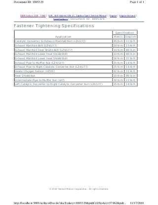
- 1. 2009 Saturn VUE - FWD | VUE, VUE Hybrid (VIN Z), Captiva Sport Service Manual | Engine | Engine Exhaust | Specifications | Document ID: 1885329 Fastener Tightening Specifications Application Specification Metric English Catalytic Converter to Exhaust Manifold Nut (LZ4/LY7) 45 N·m 33 lb ft Exhaust Manifold Bolt (LZ4/LY7) 20 N·m 15 lb ft Exhaust Manifold Heat Shield Bolt (LZ4/LY7) 10 N·m 89 lb in Exhaust Manifold Lower Heat Shield Bolt 10 N·m 89 lb in Exhaust Manifold Lower Heat Shield Bolt 50 N·m 37 lb ft Exhaust Pipe to Muffler Nut (LZ4/LY7) 25 N·m 18 lb ft Exhaust Pipe to Right Catalytic Converter Nut (LZ4/LY7) 25 N·m 18 lb ft Heater Oxygen Sensor (HO2S) 42 N·m 31 lb ft Heat Shield Nut 10 N·m 89 lb in Intermediate Pipe to Muffler Nut (LAT) 30 N·m 22 lb ft Left Catalytic Converter-to-Right Catalytic Converter Nut (LZ4/LY7) 25 N·m 18 lb ft © 2010 General Motors Corporation. All rights reserved. Page 1 of 1Document ID: 1885329 11/17/2010http://localhost:9001/si/showDoc.do?docSyskey=1885329&pubCellSyskey=37862&pub...
- 2. 2009 Saturn VUE - FWD | VUE, VUE Hybrid (VIN Z), Captiva Sport Service Manual | Engine | Engine Exhaust | Repair Instructions | Document ID: 2125606 Exhaust Manifold Replacement (LAT or LE5) Removal Procedure 1. Raise and support the vehicle. Refer to Lifting and Jacking the Vehicle. Caution: Do not bend the exhaust flex decoupler more than 3 degrees in any direction. Movement of more than 3 degrees will damage the exhaust flex decoupler. 2. Remove the catalytic converter to exhaust manifold nuts. 3. Pull down and back on the exhaust pipe in order to separate the catalytic converter from the exhaust manifold. 4. Remove and discard the catalytic converter gasket. © 2010 General Motors Corporation. All rights reserved. Page 1 of 4Document ID: 2125606 11/17/2010http://localhost:9001/si/showDoc.do?docSyskey=2125606&pubCellSyskey=37850&pub...
- 3. 5. Remove the air cleaner outlet duct. Refer to Air Cleaner Outlet Duct Replacement. 6. Remove the outlet duct retaining bracket. 7. Remove the exhaust manifold heat shield. Refer to Exhaust Manifold Heat Shield Replacement. 8. Remove the HO2S. Refer to Heated Oxygen Sensor 1 Replacement. 9. Remove the exhaust manifold nuts. 10. Remove the exhaust manifold. 11. Remove and discard the exhaust manifold gasket. 12. Clean and inspect all gasket mating surfaces. Installation Procedure Page 2 of 4Document ID: 2125606 11/17/2010http://localhost:9001/si/showDoc.do?docSyskey=2125606&pubCellSyskey=37850&pub...
- 4. 1. Install a NEW exhaust manifold gasket onto the studs. 2. Install the exhaust manifold to the cylinder head. Caution: Refer to Fastener Caution in the Preface section. 3. Install NEW exhaust manifold nuts and tighten to 14 N·m (10 lb ft). Page 3 of 4Document ID: 2125606 11/17/2010http://localhost:9001/si/showDoc.do?docSyskey=2125606&pubCellSyskey=37850&pub...
- 5. 4. Install a NEW catalytic converter gasket. 5. Install the catalytic converter to the exhaust manifold studs. 6. Install the catalytic converter to exhaust manifold nuts and tighten to 50 N·m (37 lb ft). 7. Lower the vehicle. 8. Install the exhaust manifold heat shield. Refer to Exhaust Manifold Heat Shield Replacement. 9. Install the air cleaner outlet duct. Refer to Air Cleaner Outlet Duct Replacement. Page 4 of 4Document ID: 2125606 11/17/2010http://localhost:9001/si/showDoc.do?docSyskey=2125606&pubCellSyskey=37850&pub...
- 6. 2009 Saturn VUE - FWD | VUE, VUE Hybrid (VIN Z), Captiva Sport Service Manual | Engine | Engine Exhaust | Repair Instructions | Document ID: 2125608 Exhaust Manifold Replacement - Left Side (LZ4) Removal Procedure 1. Remove the left side catalytic converter. Refer to Catalytic Converter Replacement - Left Side. 2. Remove the heated oxygen sensors (HO2S). Refer to Heated Oxygen Sensor Replacement - Bank 2 Sensor 1. 3. Remove the left side exhaust manifold bolts (1). 4. Remove the left side exhaust manifold and gasket. Installation Procedure © 2010 General Motors Corporation. All rights reserved. Page 1 of 2Document ID: 2125608 11/17/2010http://localhost:9001/si/showDoc.do?docSyskey=2125608&pubCellSyskey=62243&pub...
- 7. 1. Install the left side exhaust manifold and a NEW exhaust manifold gasket onto the cylinder. Caution: Refer to Fastener Caution in the Preface section. 2. Install the exhaust manifold bolts and tighten to 20 N·m (15 lb ft). 3. Install the HO2S. Refer to Heated Oxygen Sensor Replacement - Bank 2 Sensor 1. 4. Install the left side catalytic converter. Refer to Catalytic Converter Replacement - Left Side. Page 2 of 2Document ID: 2125608 11/17/2010http://localhost:9001/si/showDoc.do?docSyskey=2125608&pubCellSyskey=62243&pub...
- 8. 2009 Saturn VUE - FWD | VUE, VUE Hybrid (VIN Z), Captiva Sport Service Manual | Engine | Engine Exhaust | Repair Instructions | Document ID: 2125610 Exhaust Manifold Replacement - Left Side (LY7 or LCS) Removal Procedure 1. Remove the left side catalytic converter. Refer to Catalytic Converter Replacement - Left Side. 2. Remove the heated oxygen sensors (HO2S). Refer to Heated Oxygen Sensor Replacement - Bank 2 Sensor 1. 3. Remove the oil level indicator and tube. Refer to Oil Level Indicator and Tube Replacement. 4. Lower vehicle. 5. Remove the exhaust manifold heat shield. Refer to Exhaust Manifold Heat Shield Replacement - Left Side. 6. Remove the left side exhaust manifold bolts (1). 7. Raise the vehicle. Refer to Lifting and Jacking the Vehicle. 8. Remove the left side exhaust manifold and gasket. Installation Procedure © 2010 General Motors Corporation. All rights reserved. Page 1 of 2Document ID: 2125610 11/17/2010http://localhost:9001/si/showDoc.do?docSyskey=2125610&pubCellSyskey=62243&pub...
- 9. 1. Install the left side exhaust manifold and a NEW exhaust manifold gasket onto the cylinder. 2. Lower the vehicle. Caution: Refer to Fastener Caution in the Preface section. 3. Install the exhaust manifold bolts and tighten to 20 N·m (15 lb ft). 4. Install the HO2S. Refer to Heated Oxygen Sensor Replacement - Bank 1 Sensor 1. 5. Remove the exhaust manifold heat shield. Refer to Exhaust Manifold Heat Shield Replacement - Left Side. 6. Install the left side catalytic converter. Refer to Catalytic Converter Replacement - Left Side. 7. Install the oil level indicator and tube. Refer to Oil Level Indicator and Tube Replacement. Page 2 of 2Document ID: 2125610 11/17/2010http://localhost:9001/si/showDoc.do?docSyskey=2125610&pubCellSyskey=62243&pub...
- 10. 2009 Saturn VUE - FWD | VUE, VUE Hybrid (VIN Z), Captiva Sport Service Manual | Engine | Engine Exhaust | Repair Instructions | Document ID: 2125611 Exhaust Manifold Replacement - Right Side (LZ4) Removal Procedure 1. Remove the right side catalytic converter. Refer to Catalytic Converter Replacement - Right Side. 2. Remove the heated oxygen sensor (HO2S). Refer to Heated Oxygen Sensor Replacement - Bank 1 Sensor 1. 3. Remove the right side exhaust manifold bolts (1). 4. Remove the right side exhaust manifold and gasket. Installation Procedure © 2010 General Motors Corporation. All rights reserved. Page 1 of 2Document ID: 2125611 11/17/2010http://localhost:9001/si/showDoc.do?docSyskey=2125611&pubCellSyskey=62244&pub...
- 11. 1. Install the right side exhaust manifold and a NEW exhaust manifold gasket onto the cylinder. Caution: Refer to Fastener Caution in the Preface section. 2. Install the exhaust manifold bolts and tighten to 20 N·m (15 lb ft). 3. Install the heated oxygen sensor (HO2S). Refer to Heated Oxygen Sensor Replacement - Bank 1 Sensor 1. 4. Install the right side catalytic converter. Refer to Catalytic Converter Replacement - Right Side. Page 2 of 2Document ID: 2125611 11/17/2010http://localhost:9001/si/showDoc.do?docSyskey=2125611&pubCellSyskey=62244&pub...
- 12. 2009 Saturn VUE - FWD | VUE, VUE Hybrid (VIN Z), Captiva Sport Service Manual | Engine | Engine Exhaust | Repair Instructions | Document ID: 2125614 Exhaust Manifold Replacement - Right Side (LY7 or LCS) Removal Procedure 1. Remove the right side catalytic converter. Refer to Catalytic Converter Replacement - Right Side. 2. Remove the exhaust manifold heat shield. Refer to Exhaust Manifold Heat Shield Replacement - Right Side. 3. Remove the heated oxygen sensor (HO2S). Refer to Heated Oxygen Sensor Replacement - Bank 1 Sensor 1. 4. Remove the right side exhaust manifold bolts (1). 5. Remove the right side exhaust manifold and gasket. Installation Procedure © 2010 General Motors Corporation. All rights reserved. Page 1 of 2Document ID: 2125614 11/17/2010http://localhost:9001/si/showDoc.do?docSyskey=2125614&pubCellSyskey=62244&pub...
- 13. 1. Install the right side exhaust manifold and a NEW exhaust manifold gasket onto the cylinder. Caution: Refer to Fastener Caution in the Preface section. 2. Install the exhaust manifold bolts and tighten to 20 N·m (15 lb ft). Tighten Tighten the bolts to. 3. Install the exhaust manifold heat shield. Refer to Exhaust Manifold Heat Shield Replacement - Right Side. 4. Install the heated oxygen sensor (HO2S). Refer to Heated Oxygen Sensor Replacement - Bank 1 Sensor 1. 5. Install the right side catalytic converter. Refer to Catalytic Converter Replacement - Right Side. Page 2 of 2Document ID: 2125614 11/17/2010http://localhost:9001/si/showDoc.do?docSyskey=2125614&pubCellSyskey=62244&pub...
- 14. 2009 Saturn VUE - FWD | VUE, VUE Hybrid (VIN Z), Captiva Sport Service Manual | Engine | Engine Exhaust | Repair Instructions | Document ID: 2126302 Catalytic Converter Replacement Removal Procedure 1. Remove the heated oxygen sensor. Refer to Heated Oxygen Sensor 2 Replacement. 2. Remove the catalytic converter to exhaust manifold nuts (1). 3. Remove the catalytic converter to muffler nuts (1). 4. Separate the exhaust pipe from the catalytic converter studs. 5. Position and support the exhaust pipe out of the way.© 2010 General Motors Corporation. All rights reserved. Page 1 of 3Document ID: 2126302 11/17/2010http://localhost:9001/si/showDoc.do?docSyskey=2126302&pubCellSyskey=37817&pub...
- 15. 6. Remove the catalytic converter (2) and gasket. Installation Procedure 1. Install the catalytic converter (2) along with a NEW gasket to the exhaust manifold. 2. Position and join the exhaust pipe to the catalytic converter studs. Caution: Refer to Fastener Caution in the Preface section. 3. Install the catalytic converter to muffler nuts and tighten to 17 N·m (13 lb ft). 4. Install the catalytic converter to exhaust manifold nuts (1) and tighten to 50 N·m (37 lb ft). Page 2 of 3Document ID: 2126302 11/17/2010http://localhost:9001/si/showDoc.do?docSyskey=2126302&pubCellSyskey=37817&pub...
- 16. 5. Install the heated oxygen sensor. Refer to Heated Oxygen Sensor 2 Replacement. Page 3 of 3Document ID: 2126302 11/17/2010http://localhost:9001/si/showDoc.do?docSyskey=2126302&pubCellSyskey=37817&pub...
- 17. 2009 Saturn VUE - FWD | VUE, VUE Hybrid (VIN Z), Captiva Sport Service Manual | Engine | Engine Exhaust | Repair Instructions | Document ID: 2126303 Catalytic Converter Replacement - Left Side (LZ4) Removal Procedure Note: The catalytic converter is serviced by replacing the entire assembly. Always replace the gaskets at the front and rear flanges when servicing the catalytic converter. Never install the original gasket. 1. Remove the heated oxygen sensors (HO2S). Refer to Heated Oxygen Sensor Replacement - Bank 2 Sensor 2. 2. Lower the vehicle. 3. Remove the left side exhaust manifold heat shield bolts (1). 4. Remove the left side exhaust manifold heat shield. © 2010 General Motors Corporation. All rights reserved. Page 1 of 4Document ID: 2126303 11/17/2010http://localhost:9001/si/showDoc.do?docSyskey=2126303&pubCellSyskey=62249&pub...
- 18. 5. Remove the left side catalytic converter to exhaust manifold nuts (1). 6. Raise and support the vehicle. Refer to Lifting and Jacking the Vehicle. 7. Support the exhaust system. 8. Remove the catalytic converter to muffler nuts (1). 9. Reposition the muffler assembly rearward until the catalytic converter can be removed. 10. Remove the catalytic converter. 11. Remove the catalytic converter gaskets. 12. Clean and inspect the exhaust manifold and the exhaust pipe gasket mating surfaces. Installation Procedure Page 2 of 4Document ID: 2126303 11/17/2010http://localhost:9001/si/showDoc.do?docSyskey=2126303&pubCellSyskey=62249&pub...
- 19. 1. Install the catalytic converter gasket onto the catalytic converter. 2. Reposition the muffler assembly rearward until the catalytic converter can be installed. 3. Install the catalytic converter. Caution: Refer to Fastener Caution in the Preface section. 4. Install the catalytic converter nuts (1) and tighten to 60 N·m (44 lb ft). 5. Remove the support from the exhaust system. 6. Lower the vehicle. 7. Install the left side catalytic converter to exhaust manifold nuts (1) and tighten to 35 N·m (26 lb ft). Page 3 of 4Document ID: 2126303 11/17/2010http://localhost:9001/si/showDoc.do?docSyskey=2126303&pubCellSyskey=62249&pub...
- 20. 8. Install the exhaust manifold heat shield. 9. Install the left side exhaust manifold heat shield bolts (1) and tighten to 10 N·m (89 lb in). 10. Install the HO2S sensor. Refer to Heated Oxygen Sensor Replacement - Bank 2 Sensor 2. Page 4 of 4Document ID: 2126303 11/17/2010http://localhost:9001/si/showDoc.do?docSyskey=2126303&pubCellSyskey=62249&pub...
- 21. 2009 Saturn VUE - FWD | VUE, VUE Hybrid (VIN Z), Captiva Sport Service Manual | Engine | Engine Exhaust | Repair Instructions | Document ID: 2126304 Catalytic Converter Replacement - Left Side (LY7 or LCS) Removal Procedure Note: The catalytic converter is serviced by replacing the entire assembly. Always replace the gaskets at the front and rear flanges when servicing the catalytic converter. Never install the original gasket. 1. Remove the heated oxygen sensor (HO2S). Refer to Heated Oxygen Sensor Replacement - Bank 2 Sensor 2. 2. Lower the vehicle. 3. Disconnect the oxygen sensor electrical connector (1). © 2010 General Motors Corporation. All rights reserved. Page 1 of 5Document ID: 2126304 11/17/2010http://localhost:9001/si/showDoc.do?docSyskey=2126304&pubCellSyskey=62249&pub...
- 22. 4. Remove the left side exhaust manifold heat shield bolts (1). 5. Remove the left side exhaust manifold heat shield. 6. Remove the left side catalytic converter to exhaust manifold nuts (1). 7. Raise and support the vehicle. Refer to Lifting and Jacking the Vehicle. 8. Support the exhaust system. Page 2 of 5Document ID: 2126304 11/17/2010http://localhost:9001/si/showDoc.do?docSyskey=2126304&pubCellSyskey=62249&pub...
- 23. 9. Remove the catalytic converter to muffler nuts (1). 10. Reposition the muffler assembly rearward until the catalytic converter can be removed. 11. Remove the catalytic converter. 12. Remove the catalytic converter gaskets. 13. Clean and inspect the exhaust manifold and the exhaust pipe gasket mating surfaces. Installation Procedure 1. Install the catalytic converter gasket onto the catalytic converter. 2. Reposition the muffler assembly rearward until the catalytic converter can be installed. 3. Install the catalytic converter. Page 3 of 5Document ID: 2126304 11/17/2010http://localhost:9001/si/showDoc.do?docSyskey=2126304&pubCellSyskey=62249&pub...
- 24. Caution: Refer to Fastener Caution in the Preface section. 4. Install the catalytic converter nuts (1) and tighten to 60 N·m (44 lb ft). 5. Remove the support from the exhaust system. 6. Lower the vehicle. 7. Install the left side catalytic converter to exhaust manifold nuts (1) and tighten to 35 N·m (26 lb ft). 8. Install the exhaust manifold heat shield. 9. Install the left side exhaust manifold heat shield bolts (1) and tighten to 10 N·m (89 lb in). Page 4 of 5Document ID: 2126304 11/17/2010http://localhost:9001/si/showDoc.do?docSyskey=2126304&pubCellSyskey=62249&pub...
- 25. 10. Disconnect the oxygen sensor electrical connector (1) and tighten to . 11. Install the HO2S sensor. Refer to Heated Oxygen Sensor Replacement - Bank 2 Sensor 2. Page 5 of 5Document ID: 2126304 11/17/2010http://localhost:9001/si/showDoc.do?docSyskey=2126304&pubCellSyskey=62249&pub...
- 26. 2009 Saturn VUE - FWD | VUE, VUE Hybrid (VIN Z), Captiva Sport Service Manual | Engine | Engine Exhaust | Repair Instructions | Document ID: 2126305 Catalytic Converter Replacement - Right Side (LZ4) Removal Procedure Note: The catalytic converter is serviced by replacing the entire assembly. Always replace the gaskets at the front and rear flanges when servicing the catalytic converter. Never install the original gasket. 1. Remove the heated oxygen sensor (HO2S). Refer to Heated Oxygen Sensor Replacement - Bank 1 Sensor 2. 2. Lower the vehicle. 3. Remove the right side exhaust manifold heat shield bolts (1). 4. Remove the right side exhaust manifold heat shield. © 2010 General Motors Corporation. All rights reserved. Page 1 of 4Document ID: 2126305 11/17/2010http://localhost:9001/si/showDoc.do?docSyskey=2126305&pubCellSyskey=62250&pub...
- 27. 5. Remove the right side catalytic converter to exhaust manifold nuts (1). 6. Raise and support the vehicle. Refer to Lifting and Jacking the Vehicle. 7. Support the exhaust system. 8. Remove the catalytic converter to muffler nuts (1). 9. Reposition the muffler assembly rearward until the catalytic converter can be removed. 10. Remove the catalytic converter. 11. Remove the catalytic converter gaskets. 12. Clean and inspect the exhaust manifold and the exhaust pipe gasket mating surfaces. Installation Procedure Caution: Refer to Fastener Caution in the Preface section. Page 2 of 4Document ID: 2126305 11/17/2010http://localhost:9001/si/showDoc.do?docSyskey=2126305&pubCellSyskey=62250&pub...
- 28. 1. Install the right side catalytic converter to exhaust manifold nuts (1) and tighten to 35 N·m (26 lb ft). 2. Install the right side exhaust manifold heat shield. 3. Install the right side exhaust manifold heat shield bolts (1) and tighten to 10 N·m (89 lb in). Page 3 of 4Document ID: 2126305 11/17/2010http://localhost:9001/si/showDoc.do?docSyskey=2126305&pubCellSyskey=62250&pub...
- 29. 4. Install the exhaust manifold heat shield. 5. Install the right side exhaust manifold heat shield bolts (1) and tighten to 10 N·m (89 lb in). 6. Install the HO2S sensor. Refer to Heated Oxygen Sensor Replacement - Bank 1 Sensor 2. Page 4 of 4Document ID: 2126305 11/17/2010http://localhost:9001/si/showDoc.do?docSyskey=2126305&pubCellSyskey=62250&pub...
- 30. 2009 Saturn VUE - FWD | VUE, VUE Hybrid (VIN Z), Captiva Sport Service Manual | Engine | Engine Exhaust | Repair Instructions | Document ID: 2126307 Catalytic Converter Replacement - Right Side (LY7) Removal Procedure Note: The catalytic converter is serviced by replacing the entire assembly. Always replace the gaskets at the front and rear flanges when servicing the catalytic converter. Never install the original gasket. 1. Remove the heated oxygen sensor (HO2S). Refer to Heated Oxygen Sensor Replacement - Bank 1 Sensor 2. 2. Lower the vehicle. 3. Disconnect the engine wiring harness electrical connector from the HO2S electrical connector (1) © 2010 General Motors Corporation. All rights reserved. Page 1 of 5Document ID: 2126307 11/17/2010http://localhost:9001/si/showDoc.do?docSyskey=2126307&pubCellSyskey=62250&pub...
- 31. 4. Remove the right side exhaust manifold heat shield bolts (1). 5. Remove the right side exhaust manifold heat shield. 6. Remove the right side catalytic converter to exhaust manifold nuts (1). 7. Raise and support the vehicle. Refer to Lifting and Jacking the Vehicle. 8. Support the exhaust system. Page 2 of 5Document ID: 2126307 11/17/2010http://localhost:9001/si/showDoc.do?docSyskey=2126307&pubCellSyskey=62250&pub...
- 32. 9. Remove the catalytic converter to intermediate muffler nuts (1). 10. Reposition the muffler assembly rearward until the catalytic converter can be removed. 11. Remove the catalytic converter. 12. Remove the catalytic converter gaskets. 13. Clean and inspect the exhaust manifold and the exhaust pipe gasket mating surfaces. Installation Procedure 1. Install the catalytic converter gasket onto the catalytic converter. 2. Reposition the muffler assembly rearward until the catalytic converter can be installed. 3. Install the catalytic converter. Page 3 of 5Document ID: 2126307 11/17/2010http://localhost:9001/si/showDoc.do?docSyskey=2126307&pubCellSyskey=62250&pub...
- 33. Caution: Refer to Fastener Caution in the Preface section. 4. Install the catalytic converter to intermediate muffler nuts (1) and tighten to 60 N·m (44 lb ft). 5. Remove the support from the exhaust system. 6. Install the right side catalytic converter to exhaust manifold nuts (1) and tighten to 35 N·m (26 lb ft). 7. Install the right side exhaust manifold heat shield. 8. Install the right side exhaust manifold heat shield bolts (1) and tighten to 10 N·m (89 lb in). Page 4 of 5Document ID: 2126307 11/17/2010http://localhost:9001/si/showDoc.do?docSyskey=2126307&pubCellSyskey=62250&pub...
- 34. 9. Install the exhaust manifold heat shield. 10. Install the right side exhaust manifold heat shield bolts (1) and tighten to 10 N·m (89 lb in). 11. Connect the engine wiring harness electrical connector to the HO2S electrical connector (1) 12. Install the HO2S sensor. Refer to Heated Oxygen Sensor Replacement - Bank 1 Sensor 2. Page 5 of 5Document ID: 2126307 11/17/2010http://localhost:9001/si/showDoc.do?docSyskey=2126307&pubCellSyskey=62250&pub...
- 35. 2009 Saturn VUE - FWD | VUE, VUE Hybrid (VIN Z), Captiva Sport Service Manual | Engine | Engine Exhaust | Repair Instructions | Document ID: 2126308 Catalytic Converter Replacement - Right Side (LCS) Removal Procedure Note: The catalytic converter is serviced by replacing the entire assembly. Always replace the gaskets at the front and rear flanges when servicing the catalytic converter. Never install the original gasket. 1. Remove the heated oxygen sensor (HO2S). Refer to Heated Oxygen Sensor Replacement - Bank 1 Sensor 2. 2. Lower the vehicle. 3. Disconnect the engine wiring harness electrical connector from the HO2S electrical connector (1) © 2010 General Motors Corporation. All rights reserved. Page 1 of 5Document ID: 2126308 11/17/2010http://localhost:9001/si/showDoc.do?docSyskey=2126308&pubCellSyskey=62250&pub...
- 36. 4. Remove the right side exhaust manifold heat shield bolts (1). 5. Remove the right side exhaust manifold heat shield. 6. Remove the right side catalytic converter to exhaust manifold nuts (1, 2 and 3). 7. Raise and support the vehicle. Refer to Lifting and Jacking the Vehicle. 8. Support the exhaust system. Page 2 of 5Document ID: 2126308 11/17/2010http://localhost:9001/si/showDoc.do?docSyskey=2126308&pubCellSyskey=62250&pub...
- 37. 9. Remove the catalytic converter to intermediate muffler nuts (1). 10. Reposition the muffler assembly rearward until the catalytic converter (2) can be removed. 11. Remove the catalytic converter. 12. Remove the catalytic converter gaskets. 13. Clean and inspect the exhaust manifold and the exhaust pipe gasket mating surfaces. Installation Procedure 1. Install the catalytic converter gasket onto the catalytic converter. 2. Reposition the muffler assembly rearward until the catalytic converter (2) can be installed. 3. Install the catalytic converter. Page 3 of 5Document ID: 2126308 11/17/2010http://localhost:9001/si/showDoc.do?docSyskey=2126308&pubCellSyskey=62250&pub...
- 38. Caution: Refer to Fastener Caution in the Preface section. 4. Install the catalytic converter to intermediate muffler nuts (1) and tighten to 60 N·m (44 lb ft). 5. Remove the support from the exhaust system. 6. Tighten the right side catalytic converter to exhaust manifold nuts in the following sequence. 7. Install the right side exhaust manifold heat shield. 8. Install the right side exhaust manifold heat shield bolts (1) and tighten to 10 N·m 6.1. Tighten the nut (1) to 35 N·m (26 lb ft) 6.2. Tighten the nut (2) to 35 N·m (26 lb ft) 6.3. Tighten the nut (3) to 35 N·m (26 lb ft) Page 4 of 5Document ID: 2126308 11/17/2010http://localhost:9001/si/showDoc.do?docSyskey=2126308&pubCellSyskey=62250&pub...
- 39. (89 lb in). 9. Install the exhaust manifold heat shield. 10. Install the right side exhaust manifold heat shield bolts (1) and tighten to 10 N·m (89 lb in). 11. Connect the engine wiring harness electrical connector to the HO2S electrical connector (1) 12. Install the HO2S sensor. Refer to Heated Oxygen Sensor Replacement - Bank 1 Sensor 2. Page 5 of 5Document ID: 2126308 11/17/2010http://localhost:9001/si/showDoc.do?docSyskey=2126308&pubCellSyskey=62250&pub...
- 40. 2009 Saturn VUE - FWD | VUE, VUE Hybrid (VIN Z), Captiva Sport Service Manual | Engine | Engine Exhaust | Repair Instructions | Document ID: 2126342 Exhaust Muffler Replacement (LAT or LE5) Removal Procedure 1. Raise and suitably support the vehicle. Refer to Lifting and Jacking the Vehicle. 2. Remove the catalytic converter to muffler nuts (1). 3. With the aid of an assistant, remove the muffler insulators (1) from the hangers. 4. Remove the muffler assembly. © 2010 General Motors Corporation. All rights reserved. Page 1 of 3Document ID: 2126342 11/17/2010http://localhost:9001/si/showDoc.do?docSyskey=2126342&pubCellSyskey=37934&pub...
- 41. Installation Procedure Note: Replace the muffler hangers any time the exhaust system is removed from the vehicle. Do not use any mineral oil based lubricants or sharp tools when installing new exhaust system hangers. 1. With the aid of an assistant , position the muffler assembly. 2. Install the muffler insulators (1) to the hangers. Caution: Refer to Fastener Caution in the Preface section. Page 2 of 3Document ID: 2126342 11/17/2010http://localhost:9001/si/showDoc.do?docSyskey=2126342&pubCellSyskey=37934&pub...
- 42. 3. Install the catalytic converter to muffler nuts and tighten to 25 N·m. Page 3 of 3Document ID: 2126342 11/17/2010http://localhost:9001/si/showDoc.do?docSyskey=2126342&pubCellSyskey=37934&pub...
- 43. 2009 Saturn VUE - FWD | VUE, VUE Hybrid (VIN Z), Captiva Sport Service Manual | Engine | Engine Exhaust | Repair Instructions | Document ID: 2126344 Exhaust Muffler Replacement (LZ4) Removal Procedure 1. Raise and suitably support the vehicle. Refer to Lifting and Jacking the Vehicle. 2. Remove the catalytic converter to muffler nuts (1). 3. With the aid of an assistant, remove the muffler insulators (1) from the hangers. 4. Remove the muffler assembly.© 2010 General Motors Corporation. All rights reserved. Page 1 of 3Document ID: 2126344 11/17/2010http://localhost:9001/si/showDoc.do?docSyskey=2126344&pubCellSyskey=37934&pub...
- 44. Installation Procedure Note: Replace the muffler hangers any time the exhaust system is removed from the vehicle. Do not use any mineral oil based lubricants or sharp tools when installing new exhaust system hangers. 1. With the aid of an assistant , position the muffler assembly. 2. Install the muffler insulators (1) to the hangers. Caution: Refer to Fastener Caution in the Preface section. Page 2 of 3Document ID: 2126344 11/17/2010http://localhost:9001/si/showDoc.do?docSyskey=2126344&pubCellSyskey=37934&pub...
- 45. 3. Install the catalytic converter to muffler nuts and tighten to 25 N·m (18 lb ft). Page 3 of 3Document ID: 2126344 11/17/2010http://localhost:9001/si/showDoc.do?docSyskey=2126344&pubCellSyskey=37934&pub...
- 46. 2009 Saturn VUE - FWD | VUE, VUE Hybrid (VIN Z), Captiva Sport Service Manual | Engine | Engine Exhaust | Repair Instructions | Document ID: 2126346 Exhaust Muffler Replacement (LY7) Removal Procedure 1. Raise and suitably support the vehicle. Refer to Lifting and Jacking the Vehicle. 2. Remove the catalytic converter to muffler nuts (1). 3. With the aid of an assistant, remove the muffler insulators (1) from the hangers. 4. Remove the muffler assembly. © 2010 General Motors Corporation. All rights reserved. Page 1 of 3Document ID: 2126346 11/17/2010http://localhost:9001/si/showDoc.do?docSyskey=2126346&pubCellSyskey=37934&pub...
- 47. Installation Procedure Note: Replace the muffler hangers any time the exhaust system is removed from the vehicle. Do not use any mineral oil based lubricants or sharp tools when installing new exhaust system hangers. 1. With the aid of an assistant , position the muffler assembly. 2. Install the muffler insulators (1) to the hangers. Caution: Refer to Fastener Caution in the Preface section. Page 2 of 3Document ID: 2126346 11/17/2010http://localhost:9001/si/showDoc.do?docSyskey=2126346&pubCellSyskey=37934&pub...
- 48. 3. Install the catalytic converter to muffler nuts and tighten to 25 N·m (18 lb ft). Page 3 of 3Document ID: 2126346 11/17/2010http://localhost:9001/si/showDoc.do?docSyskey=2126346&pubCellSyskey=37934&pub...
- 49. 2009 Saturn VUE - FWD | VUE, VUE Hybrid (VIN Z), Captiva Sport Service Manual | Engine | Engine Exhaust | Repair Instructions | Document ID: 2126347 Exhaust Muffler Replacement (LCS) Callout Component Name Preliminary Procedures Raise and support the vehicle. Refer to Lifting and Jacking the Vehicle 1 Nut (Qty: 2) Caution: Refer to Fastener Caution in the Preface section. Tighten 60 N·m (44 lb ft) 2 Hanger (Qty:5) 3 Muffler Assembly Procedure With the aid of an assistant remove the muffler assembly © 2010 General Motors Corporation. All rights reserved. Page 1 of 1Document ID: 2126347 11/17/2010http://localhost:9001/si/showDoc.do?docSyskey=2126347&pubCellSyskey=37934&pub...
- 50. 2009 Saturn VUE - FWD | VUE, VUE Hybrid (VIN Z), Captiva Sport Service Manual | Engine | Engine Exhaust | Repair Instructions | Document ID: 2126351 Exhaust Manifold Heat Shield Replacement (LAT or LE5) Removal Procedure 1. Remove the air cleaner outlet duct. Refer to Air Cleaner Outlet Duct Replacement. 2. On the LAT engine, remove the air cleaner bracket nuts (1). 3. Remove the air cleaner bracket. 4. Remove the exhaust manifold heat shield studs (2). 5. Remove the exhaust manifold heat shield (1).© 2010 General Motors Corporation. All rights reserved. Page 1 of 2Document ID: 2126351 11/17/2010http://localhost:9001/si/showDoc.do?docSyskey=2126351&pubCellSyskey=64786&pub...
- 51. Installation Procedure 1. Install the exhaust manifold heat shield (1). Caution: Refer to Fastener Caution in the Preface section. 2. Install the exhaust manifold heat shield studs (2) and tighten to 22 N·m (16 lb ft). 3. On the LAT engine, install the air cleaner bracket. 4. Install the air cleaner bracket nuts (1) and tighten to 20 N·m (15 lb ft. 5. Install the air cleaner outlet duct. Refer to Air Cleaner Outlet Duct Replacement. Page 2 of 2Document ID: 2126351 11/17/2010http://localhost:9001/si/showDoc.do?docSyskey=2126351&pubCellSyskey=64786&pub...
- 52. 2009 Saturn VUE - FWD | VUE, VUE Hybrid (VIN Z), Captiva Sport Service Manual | Engine | Engine Exhaust | Repair Instructions | Document ID: 2126353 Exhaust Manifold Heat Shield Replacement - Right Side (LY7 or LCS) Removal Procedure 1. Remove the fuel injector sight shield. Refer to Fuel Injector Sight Shield Replacement. 2. Disconnect the engine wiring harness electrical connector (3) from the heated oxygen sensor (HO2S) electrical connector (4). 3. Remove the HO2S electrical connector retainer (5) from the retainer clip. © 2010 General Motors Corporation. All rights reserved. Page 1 of 3Document ID: 2126353 11/17/2010http://localhost:9001/si/showDoc.do?docSyskey=2126353&pubCellSyskey=81128&pub...
- 53. 4. Remove the exhaust manifold heat shield bolts (1). 5. Remove the exhaust manifold heat shield (2). Installation Procedure Caution: Refer to Fastener Caution in the Preface section. 1. Install the exhaust manifold heat shield (2). 2. Install the exhaust manifold heat shield bolts (1) and tighten to 22 N·m (16 lb ft). Page 2 of 3Document ID: 2126353 11/17/2010http://localhost:9001/si/showDoc.do?docSyskey=2126353&pubCellSyskey=81128&pub...
- 54. 3. Connect the engine harness electrical connector (3) to the HO2S electrical connector (4). 4. Install the HO2S electrical connector retainer (5) to the retainer clip. 5. Install the fuel injector sight shield. Refer to Fuel Injector Sight Shield Replacement. Page 3 of 3Document ID: 2126353 11/17/2010http://localhost:9001/si/showDoc.do?docSyskey=2126353&pubCellSyskey=81128&pub...
- 55. 2009 Saturn VUE - FWD | VUE, VUE Hybrid (VIN Z), Captiva Sport Service Manual | Engine | Engine Exhaust | Repair Instructions | Document ID: 2126357 Exhaust Manifold Heat Shield Replacement - Right Side (LZ4) Removal Procedure 1. Remove the intake manifold cover. Refer to Intake Manifold Cover Replacement. 2. Remove the connector position assurance (CPA) retainer. 3. Disconnect the engine wiring harness electrical connector (3) from the heated oxygen sensor (HO2S) electrical connector (2). 4. Remove the HO2S electrical connector rosebud clip from the engine wiring harness retainer strap (6). © 2010 General Motors Corporation. All rights reserved. Page 1 of 3Document ID: 2126357 11/17/2010http://localhost:9001/si/showDoc.do?docSyskey=2126357&pubCellSyskey=81128&pub...
- 56. 5. Remove the exhaust manifold heat shield bolts (1). 6. Remove the exhaust manifold heat shield (2). Installation Procedure 1. Install the exhaust manifold heat shield (2). Caution: Refer to Fastener Caution in the Preface section. 2. Install the exhaust manifold heat shield bolts (1) and tighten to 22 N·m (16 lb ft). Page 2 of 3Document ID: 2126357 11/17/2010http://localhost:9001/si/showDoc.do?docSyskey=2126357&pubCellSyskey=81128&pub...
- 57. 3. Connect the engine harness electrical connector (3) to the HO2S electrical connector (2). 4. Install the CPA retainer. 5. Install the HO2S electrical connector rosebud clip to the engine wiring harness retaining strap (6). 6. Install the intake manifold cover. Refer to Intake Manifold Cover Replacement. Page 3 of 3Document ID: 2126357 11/17/2010http://localhost:9001/si/showDoc.do?docSyskey=2126357&pubCellSyskey=81128&pub...
- 58. 2009 Saturn VUE - FWD | VUE, VUE Hybrid (VIN Z), Captiva Sport Service Manual | Engine | Engine Exhaust | Repair Instructions | Document ID: 2126363 Exhaust Manifold Heat Shield Replacement - Left Side (LY7 or LCS) Removal Procedure 1. Remove the fuel injector sight shield. Refer to Fuel Injector Sight Shield Replacement. 2. Disconnect the engine wiring harness electrical connector (3) from the heated oxygen sensors (HO2S) electrical connector (2). © 2010 General Motors Corporation. All rights reserved. Page 1 of 2Document ID: 2126363 11/17/2010http://localhost:9001/si/showDoc.do?docSyskey=2126363&pubCellSyskey=81129&pub...
- 59. 3. Remove the exhaust manifold heat shield bolts (1). 4. Remove the exhaust manifold heat shield (2). Installation Procedure Caution: Refer to Fastener Caution in the Preface section. 1. Install the exhaust manifold heat shield (2). 2. Install the exhaust manifold heat shield bolts (1) and tighten to 22 N·m (16 lb ft). 3. Connect the engine harness electrical connector (1) to the HO2S (2). 4. Install the fuel injector sight shield. Refer to Fuel Injector Sight Shield Replacement. Page 2 of 2Document ID: 2126363 11/17/2010http://localhost:9001/si/showDoc.do?docSyskey=2126363&pubCellSyskey=81129&pub...
- 60. 2009 Saturn VUE - FWD | VUE, VUE Hybrid (VIN Z), Captiva Sport Service Manual | Engine | Engine Exhaust | Repair Instructions | Document ID: 2126367 Exhaust Manifold Heat Shield Replacement - Left Side (LZ4) Removal Procedure 1. Remove the intake manifold cover. Refer to Intake Manifold Cover Replacement. 2. Remove the connector position assurance (CPA) retainer. 3. Disconnect the engine wiring harness electrical connector (3) from the heated oxygen sensors (HO2S) electrical connector (2). © 2010 General Motors Corporation. All rights reserved. Page 1 of 3Document ID: 2126367 11/17/2010http://localhost:9001/si/showDoc.do?docSyskey=2126367&pubCellSyskey=81129&pub...
- 61. 4. Remove the exhaust manifold heat shield bolts (1). 5. Remove the exhaust manifold heat shield (2). Installation Procedure Caution: Refer to Fastener Caution in the Preface section. 1. Install the exhaust manifold heat shield (2). 2. Install the exhaust manifold heat shield bolts (1) and tighten to 22 N·m (16 lb ft). Page 2 of 3Document ID: 2126367 11/17/2010http://localhost:9001/si/showDoc.do?docSyskey=2126367&pubCellSyskey=81129&pub...
- 62. 3. Connect the engine harness electrical connector (1) to the HO2S (2). 4. Install the CPA retainer. 5. Install the intake manifold cover. Refer to Intake Manifold Cover Replacement. Page 3 of 3Document ID: 2126367 11/17/2010http://localhost:9001/si/showDoc.do?docSyskey=2126367&pubCellSyskey=81129&pub...
- 63. Hello Thank you very much for your patience. At the bottom of the page there is a FREE ADD TO CART button. Click on it and you will get zip file on the bottom Please click here. Go back to the page. of the page.