SlideShare a Scribd company logo
1 of 49
Download to read offline
1996 Buick Skylark | Achieva, Grand Am, Skylark (VIN N) Service Manual | Engine | Engine Mechanical - 2.4L |
Repair Instructions | Document ID: 60142
Drive Belt Replacement
Removal Procedure
Tools Required
J 37059 Accessory Drive Belt Tensioner Wrench
Caution: To avoid personal injury when rotating the accessory drive belt tensioner, use a tight
fitting 13 mm wrench that is at least 46 cm (18 in) long.
Use J 37059 in order to remove the accessory drive belt by rotating the tensioner.
Installation Procedure
Tools Required
J 37059 Accessory Drive Belt Tensioner Wrench
Caution: To avoid personal injury when rotating the accessory drive belt tensioner, use a tight
fitting 13 mm wrench that is at least 46 cm (18 in) long.
© 2010 General Motors Corporation. All rights reserved.
Page 1 of 2Document ID: 60142
10/12/2010http://localhost:9001/si/showDoc.do?docSyskey=60142&pubCellSyskey=39343&pubObj...
tomsn048@gmail.com
Use J 37059 in order to install the accessory drive belt by rotating the tensioner.
Page 2 of 2Document ID: 60142
10/12/2010http://localhost:9001/si/showDoc.do?docSyskey=60142&pubCellSyskey=39343&pubObj...
tomsn048@gmail.com
1996 Buick Skylark | Achieva, Grand Am, Skylark (VIN N) Service Manual | Engine | Engine Mechanical - 2.4L |
Repair Instructions | Document ID: 60815
Drive Belt Tensioner Replacement
Removal Procedure
1. Disconnect the negative battery cable.
Caution: Unless directed otherwise, the ignition and start switch must be in the OFF or LOCK
position, and all electrical loads must be OFF before servicing any electrical component.
Disconnect the negative battery cable to prevent an electrical spark should a tool or
equipment come in contact with an exposed electrical terminal. Failure to follow these
precautions may result in personal injury and/or damage to the vehicle or its components.
in General Information.
2. Remove the accessory drive belt. Refer to Drive Belt Replacement .
3. Remove the generator assembly. Refer to Generator Replacement in Engine Electrical.
4. Raise and support the vehicle. Refer to SECTION 0A.
5. Remove the oil filter.
6. Refer to Drive Belt Idler Pulley Replacement
7. Remove the tensioner.
Installation Procedure
6.1. The A/C compressor mounting bolt
6.2. The A/C compressor. Position it aside.
© 2010 General Motors Corporation. All rights reserved.
Page 1 of 3Document ID: 60815
10/12/2010http://localhost:9001/si/showDoc.do?docSyskey=60815&pubCellSyskey=39344&pubObj...
tomsn048@gmail.com
1. Install the tensioner.
Tighten
Tighten the tensioner nut to 50 N·m (37 lb ft).
2. Refer to Drive Belt Idler Pulley Replacement
Tighten
Tighten the bolts to 54 N·m (40 lb ft).
2.1. The A/C compressor. Refer to SECTION 1B.
2.2. The A/C compressor mounting bolts. Refer to SECTION 1B.
Page 2 of 3Document ID: 60815
10/12/2010http://localhost:9001/si/showDoc.do?docSyskey=60815&pubCellSyskey=39344&pubObj...
tomsn048@gmail.com
3. Install the oil filter.
4. Lower the vehicle.
5. Install the generator assembly. Refer to Generator Replacement in Engine Electrical.
6. Install the drive belt. Refer to Drive Belt Replacement .
7. Connect the negative battery cable.
Page 3 of 3Document ID: 60815
10/12/2010http://localhost:9001/si/showDoc.do?docSyskey=60815&pubCellSyskey=39344&pubObj...
tomsn048@gmail.com
1996 Buick Skylark | Achieva, Grand Am, Skylark (VIN N) Service Manual | Engine | Engine Mechanical - 2.4L |
Repair Instructions | Document ID: 60819
Drive Belt Idler Pulley Replacement
Removal Procedure
1. Disconnect the negative battery cable. Refer to
Caution: Unless directed otherwise, the ignition and start switch must be in the OFF or LOCK
position, and all electrical loads must be OFF before servicing any electrical component.
Disconnect the negative battery cable to prevent an electrical spark should a tool or
equipment come in contact with an exposed electrical terminal. Failure to follow these
precautions may result in personal injury and/or damage to the vehicle or its components.
in General Information.
2. Remove the accessory drive belt. Refer to Drive Belt Replacement .
3. Remove the idler pulley bracket and bolts.
4. Remove the idler pulley.
Installation Procedure
Notice: Use the correct fastener in the correct location. Replacement fasteners must be the
correct part number for that application. Fasteners requiring replacement or fasteners
requiring the use of thread locking compound or sealant are identified in the service
procedure. Do not use paints, lubricants, or corrosion inhibitors on fasteners or fastener joint
surfaces unless specified. These coatings affect fastener torque and joint clamping force and
may damage the fastener. Use the correct tightening sequence and specifications when
installing fasteners in order to avoid damage to parts and systems.
© 2010 General Motors Corporation. All rights reserved.
Page 1 of 2Document ID: 60819
10/12/2010http://localhost:9001/si/showDoc.do?docSyskey=60819&pubCellSyskey=39414&pubObj...
tomsn048@gmail.com
1. Install the idler pulley.
2. Install the idler pulley bracket and bolts.
Tighten
Tighten the bolts to 50 N·m (37 lb ft).
3. Install the drive belt. Refer to Drive Belt Replacement .
4. Connect the negative battery cable.
Page 2 of 2Document ID: 60819
10/12/2010http://localhost:9001/si/showDoc.do?docSyskey=60819&pubCellSyskey=39414&pubObj...
tomsn048@gmail.com
1996 Buick Skylark | Achieva, Grand Am, Skylark (VIN N) Service Manual | Engine | Engine Mechanical - 2.4L |
Repair Instructions | Document ID: 60824
Engine Mount Replacement
Removal Procedure
Tools Required
J 28467-360 Engine Support Fixture
1. Disconnect the negative battery cable. Refer to
Caution: Unless directed otherwise, the ignition and start switch must be in the OFF or LOCK
position, and all electrical loads must be OFF before servicing any electrical component.
Disconnect the negative battery cable to prevent an electrical spark should a tool or
equipment come in contact with an exposed electrical terminal. Failure to follow these
precautions may result in personal injury and/or damage to the vehicle or its components.
in General Information.
2. Remove the one bolt attaching the coolant recovery tank. Refer to Coolant Recovery Tank
Replacement in Engine Cooling.
3. Remove the coolant recovery tank and position it aside.
4. Install the J 28467-360 and raise the engine off of the mount.
5. Remove the nuts holding the mount to the body.
6. Remove the bolts holding the engine bracket to the mount.
7. Remove the engine mount assembly.
Installation Procedure
Tools Required
© 2010 General Motors Corporation. All rights reserved.
Page 1 of 2Document ID: 60824
10/12/2010http://localhost:9001/si/showDoc.do?docSyskey=60824&pubCellSyskey=39423&pubObj...
tomsn048@gmail.com
J 28467-360 Engine Support Fixture
1. Install the engine mount assembly.
2. Install the nuts holding the mount to the body. Do not tighten.
3. Install the bolts holding the engine bracket to the mount.
Tighten
Notice: Use the correct fastener in the correct location. Replacement fasteners must be the
correct part number for that application. Fasteners requiring replacement or fasteners
requiring the use of thread locking compound or sealant are identified in the service
procedure. Do not use paints, lubricants, or corrosion inhibitors on fasteners or fastener joint
surfaces unless specified. These coatings affect fastener torque and joint clamping force and
may damage the fastener. Use the correct tightening sequence and specifications when
installing fasteners in order to avoid damage to parts and systems.
4. Remove the J 28467-360 .
5. Install the coolant recovery tank. Refer to Coolant Recover Tank Replacement in Engine
Cooling.
6. Connect the negative battery cable.
• Tighten the bolts holding the engine bracket to the mount to 60 N·m (44 lb ft) +
90 degrees.
• Tighten the nuts holding the mount to the body to 75 N·m (55 lb ft).
Page 2 of 2Document ID: 60824
10/12/2010http://localhost:9001/si/showDoc.do?docSyskey=60824&pubCellSyskey=39423&pubObj...
tomsn048@gmail.com
1996 Buick Skylark | Achieva, Grand Am, Skylark (VIN N) Service Manual | Engine | Engine Mechanical - 2.4L |
Repair Instructions | Document ID: 61738
Engine Mount Strut Replacement
Removal Procedure
1. Disconnect the negative battery cable. Refer to
Caution: Unless directed otherwise, the ignition and start switch must be in the OFF or LOCK
position, and all electrical loads must be OFF before servicing any electrical component.
Disconnect the negative battery cable to prevent an electrical spark should a tool or
equipment come in contact with an exposed electrical terminal. Failure to follow these
precautions may result in personal injury and/or damage to the vehicle or its components.
in General Information.
2. Raise and support the vehicle. Refer to SECTION 0A.
3. Remove the right front splash shield.
4. Remove the engine mount strut bolts.
5. Remove the engine mount strut.
Installation Procedure
© 2010 General Motors Corporation. All rights reserved.
Page 1 of 2Document ID: 61738
10/12/2010http://localhost:9001/si/showDoc.do?docSyskey=61738&pubCellSyskey=39425&pubObj...
tomsn048@gmail.com
1. Install the engine mount strut.
2. Install the engine mount strut bolts.
Tighten
Tighten the strut bolts to 100 N·m (74 lb ft) + 90 degrees.
Notice: Use the correct fastener in the correct location. Replacement fasteners must be the
correct part number for that application. Fasteners requiring replacement or fasteners
requiring the use of thread locking compound or sealant are identified in the service
procedure. Do not use paints, lubricants, or corrosion inhibitors on fasteners or fastener joint
surfaces unless specified. These coatings affect fastener torque and joint clamping force and
may damage the fastener. Use the correct tightening sequence and specifications when
installing fasteners in order to avoid damage to parts and systems.
3. Install the right front splash shield.
4. Lower the vehicle.
5. Connect the negative battery cable.
Page 2 of 2Document ID: 61738
10/12/2010http://localhost:9001/si/showDoc.do?docSyskey=61738&pubCellSyskey=39425&pubObj...
tomsn048@gmail.com
1996 Buick Skylark | Achieva, Grand Am, Skylark (VIN N) Service Manual | Engine | Engine Mechanical - 2.4L |
Repair Instructions | Document ID: 60826
Intake Manifold Replacement
Removal Procedure
1. Disconnect the negative battery cable. Refer to
Caution: Unless directed otherwise, the ignition and start switch must be in the OFF or LOCK
position, and all electrical loads must be OFF before servicing any electrical component.
Disconnect the negative battery cable to prevent an electrical spark should a tool or
equipment come in contact with an exposed electrical terminal. Failure to follow these
precautions may result in personal injury and/or damage to the vehicle or its components.
in General Information.
2. Disconnect the following electrical connectors:
3. Disconnect the vacuum hoses from the fuel regulator and the EVAP Canister Purge solenoid
to the canister.
4. Remove the air cleaner duct.
5. Remove the accelerator control cable bracket.
6. Remove the stud ended generator mount bolt.
• MAP sensor
• Intake Air Temperature (IAT) sensor
• EVAP Canister Purge solenoid
• Fuel injector harness
© 2010 General Motors Corporation. All rights reserved.
Page 1 of 6Document ID: 60826
10/12/2010http://localhost:9001/si/showDoc.do?docSyskey=60826&pubCellSyskey=39398&pubObj...
tomsn048@gmail.com
7. Remove the EGR pipe from the EGR adapter.
8. Raise and support the vehicle. Refer to SECTION 0A.
9. Remove the intake manifold support brace.
10. Lower the vehicle.
Page 2 of 6Document ID: 60826
10/12/2010http://localhost:9001/si/showDoc.do?docSyskey=60826&pubCellSyskey=39398&pubObj...
tomsn048@gmail.com
11. Remove the intake manifold retaining nuts and bolts.
12. Remove the intake manifold and the gasket.
Installation Procedure
Important: The engine and the manifold should be at ambient temperature when
assembled. Do not attempt to install a cold manifold on a hot engine.
1. Install the intake manifold and the gasket. If the gasket is damaged, install a new one with
the stamped numbers facing towards the manifold surface.
Page 3 of 6Document ID: 60826
10/12/2010http://localhost:9001/si/showDoc.do?docSyskey=60826&pubCellSyskey=39398&pubObj...
tomsn048@gmail.com
2. Install the intake manifold fasteners.
Tighten
Tighten the fasteners to 24 N·m (18 lb ft).
Notice: Use the correct fastener in the correct location. Replacement fasteners must be the
correct part number for that application. Fasteners requiring replacement or fasteners
requiring the use of thread locking compound or sealant are identified in the service
procedure. Do not use paints, lubricants, or corrosion inhibitors on fasteners or fastener joint
surfaces unless specified. These coatings affect fastener torque and joint clamping force and
may damage the fastener. Use the correct tightening sequence and specifications when
installing fasteners in order to avoid damage to parts and systems.
3. Raise and suitably support the vehicle. Refer to SECTION 0A.
Page 4 of 6Document ID: 60826
10/12/2010http://localhost:9001/si/showDoc.do?docSyskey=60826&pubCellSyskey=39398&pubObj...
tomsn048@gmail.com
4. Install the intake manifold brace. Finger start all bolts.
Tighten
5. Lower the vehicle.
6. Connect the EGR pipe to the EGR adapter.
7. Install the EGR pipe to the EGR adapter fasteners.
Tighten
Tighten the fasteners to 26 N·m (19 lb ft).
• Tighten bolt (A) to 24 N·m (18 lb ft).
• Tighten bolt (B) to 26 N·m (19 lb ft).
Page 5 of 6Document ID: 60826
10/12/2010http://localhost:9001/si/showDoc.do?docSyskey=60826&pubCellSyskey=39398&pubObj...
tomsn048@gmail.com
8. Install the stud ended generator mount bolt.
9. Install the accelerator control cable bracket.
10. Connect the vacuum hoses to the fuel regulator and to the EVAP canister purge solenoid.
Important: If the Intake Air Temperature (IAT) sensor is removed, apply sealant
GM P/N 1052080 or equivalent to its threads before installation.
11. Connect the following electrical connections:
12. Install the air cleaner duct.
13. Connect the negative battery cable.
• MAP sensor
• IAT sensor
• EVAP canister purge solenoid
• Fuel injector harness
Page 6 of 6Document ID: 60826
10/12/2010http://localhost:9001/si/showDoc.do?docSyskey=60826&pubCellSyskey=39398&pubObj...
tomsn048@gmail.com
1996 Buick Skylark | Achieva, Grand Am, Skylark (VIN N) Service Manual | Engine | Engine Mechanical - 2.4L |
Repair Instructions | Document ID: 60838
Exhaust Manifold Replacement
Removal Procedure
1. Disconnect the negative battery cable. Refer to
Caution: Unless directed otherwise, the ignition and start switch must be in the OFF or LOCK
position, and all electrical loads must be OFF before servicing any electrical component.
Disconnect the negative battery cable to prevent an electrical spark should a tool or
equipment come in contact with an exposed electrical terminal. Failure to follow these
precautions may result in personal injury and/or damage to the vehicle or its components.
in General Information.
2. Disconnect the O2S (Oxygen) sensor connector.
3. Raise and support the vehicle. Refer to SECTION 0A.
4. Remove the exhaust manifold brace to manifold fasteners.
© 2010 General Motors Corporation. All rights reserved.
Page 1 of 6Document ID: 60838
10/12/2010http://localhost:9001/si/showDoc.do?docSyskey=60838&pubCellSyskey=39364&pubObj...
tomsn048@gmail.com
5. Remove the upper heat shield.
Notice: Do not bend the exhaust flex decoupler more than 3 degrees in any direction.
Movement of more than 3 degrees will damage the exhaust flex decoupler.
6. Remove the manifold to the exhaust flex decoupler fasteners.
Page 2 of 6Document ID: 60838
10/12/2010http://localhost:9001/si/showDoc.do?docSyskey=60838&pubCellSyskey=39364&pubObj...
tomsn048@gmail.com
7. Pull down and back on the exhaust pipe to disengage it from the exhaust manifold.
8. Lower the vehicle.
9. Remove the exhaust manifold to cylinder head retaining nuts.
10. Remove the exhaust manifold, seals and gaskets.
11. Clean all sealing surfaces.
Installation Procedure
1. Install a new exhaust manifold gasket.
2. Install the exhaust manifold.
Page 3 of 6Document ID: 60838
10/12/2010http://localhost:9001/si/showDoc.do?docSyskey=60838&pubCellSyskey=39364&pubObj...
tomsn048@gmail.com
3. Install the exhaust manifold nuts.
Tighten
Tighten the nuts to 13 N·m (110 lb in).
Notice: Use the correct fastener in the correct location. Replacement fasteners must be the
correct part number for that application. Fasteners requiring replacement or fasteners
requiring the use of thread locking compound or sealant are identified in the service
procedure. Do not use paints, lubricants, or corrosion inhibitors on fasteners or fastener joint
surfaces unless specified. These coatings affect fastener torque and joint clamping force and
may damage the fastener. Use the correct tightening sequence and specifications when
installing fasteners in order to avoid damage to parts and systems.
4. Raise and support the vehicle. Refer to SECTION 0A.
Page 4 of 6Document ID: 60838
10/12/2010http://localhost:9001/si/showDoc.do?docSyskey=60838&pubCellSyskey=39364&pubObj...
tomsn048@gmail.com
5. Install the heat shield.
Tighten
Tighten the bolts to 14 N·m (124 lb in).
6. Install the exhaust manifold brace to exhaust manifold fasteners.
Tighten
• Tighten the bolt to 56 N·m (41 lb ft).
• Tighten the nuts to 26 N·m (19 lb ft).
Page 5 of 6Document ID: 60838
10/12/2010http://localhost:9001/si/showDoc.do?docSyskey=60838&pubCellSyskey=39364&pubObj...
tomsn048@gmail.com
7. Install the manifold to the flex decoupler fasteners.
Tighten
Tighten the fasteners to 35 N·m (26 lb ft).
8. Lower the vehicle.
9. Coat the threads of the O2S (Oxygen sensor) connector with anti-seize compound
GM P/N 5613695 or equivalent.
10. Connect the O2S (Oxygen sensor) connector.
11. Connect the negative battery cable.
Page 6 of 6Document ID: 60838
10/12/2010http://localhost:9001/si/showDoc.do?docSyskey=60838&pubCellSyskey=39364&pubObj...
tomsn048@gmail.com
1996 Buick Skylark | Achieva, Grand Am, Skylark (VIN N) Service Manual | Engine | Engine Mechanical - 2.4L |
Repair Instructions | Document ID: 61378
Intake Camshaft, Housing and Lifter Replacement
Removal Procedure
Tools Required
Important:
1. Disconnect the negative battery cable. Refer to
Caution: Unless directed otherwise, the ignition and start switch must be in the OFF or LOCK
position, and all electrical loads must be OFF before servicing any electrical component.
Disconnect the negative battery cable to prevent an electrical spark should a tool or
equipment come in contact with an exposed electrical terminal. Failure to follow these
precautions may result in personal injury and/or damage to the vehicle or its components.
in General Information.
2. Remove the ignition coil and the module assembly electrical connections.
3. Remove the ignition coil and the module assembly to the camshaft housing bolts.
• J 36660-A Torque Angle Meter
• J 36011 Spark Plug Connector Assembly Remover
• Any time the camshaft housing to the cylinder head bolts are loosened or removed, the
camshaft housing to the cylinder head gasket must be replaced.
• During disassembly, ensure that the valve lifters are kept together and identified so
that they can be reinstalled in the original locations.
• Before disassembling the valve mechanism, make a compression test and note the
results. Refer to Engine Compression Test .
© 2010 General Motors Corporation. All rights reserved.
Page 1 of 9Document ID: 61378
10/12/2010http://localhost:9001/si/showDoc.do?docSyskey=61378&pubCellSyskey=39491&pubObj...
tomsn048@gmail.com
4. Remove the assembly by pulling straight up.
5. Use the J 36011 in order to remove the connector assembly if stuck to the spark plugs. Use
the tool by first twisting then pulling up on the connector assembly.
6. Remove the camshaft position sensor connector.
7. Remove the power steering pump and position aside.
Do not disconnect the power steering lines.
8. Remove the vacuum line from the fuel pressure regulator and the fuel injector harness
connector.
9. Remove the fuel line retaining clamp from the bracket on top of the intake camshaft housing.
10. Remove the fuel rail to the camshaft housing retaining bolts.
Page 2 of 9Document ID: 61378
10/12/2010http://localhost:9001/si/showDoc.do?docSyskey=61378&pubCellSyskey=39491&pubObj...
tomsn048@gmail.com
11. Remove the fuel rail from the cylinder head as follows:
12. Disconnect, but do not remove from the vehicle, the timing chain housing at the intake
camshaft housing. Refer to Timing Chain Housing Replacement .
13. Remove the camshaft housing cover to the camshaft housing retaining bolts.
Important:
• Cover the injector openings in the cylinder head.
• Cover the injector nozzles.
• Leave the fuel lines attached and the position fuel rail aside (on top of the master
cylinder).
• Use the reverse of the tightening procedure when loosening the camshaft housing to
the cylinder head retaining bolts.
Page 3 of 9Document ID: 61378
10/12/2010http://localhost:9001/si/showDoc.do?docSyskey=61378&pubCellSyskey=39491&pubObj...
tomsn048@gmail.com
14. Remove the camshaft housing to the cylinder head retaining bolts.
Important: Tighten the bolts evenly in order to prevent the cover from binding on the dowel
pins.
15. Push the cover off the housing by threading four of the housing to head retaining bolts into
the tapped holes in the camshaft housing cover.
16. Remove the two loosely installed camshaft housing to head bolts.
17. Remove the cover and discard the gaskets.
18. Loosely reinstall one camshaft housing to cylinder head bolt in order to retain the housing
during the camshaft and lifter removal.
19. Note the position of the chain sprocket dowel pin for reassembly.
Remove the camshaft being careful not to damage the camshaft or the journals.
Important: The valve lifters are not serviceable. Replace faulty valve lifters.
Coat the valve lifter with the Camshaft and Lifter Prelube GM P/N 12345501 or the
equivalent. If the new lifters are installed, add the Engine Oil Supplement GM P/N 1052367,
or the equivalent, to the engine oil.
20. Remove the valve lifters as follows:
Important: Ensure that the alignment dowel pins are in the cylinder head prior to installing
the camshaft housing.
• Leave the two bolts loosely in place in order to hold the camshaft housing while
separating the camshaft cover from the housing.
• Keep the lifters in order to reinstall the lifters to the original locations.
• In order to minimize the lifter bleed down, perform the following procedure:
- Store the lifters upside down, opposite of the installed position, on a level surface.
- Store the lifters submerged in clean engine oil.
Page 4 of 9Document ID: 61378
10/12/2010http://localhost:9001/si/showDoc.do?docSyskey=61378&pubCellSyskey=39491&pubObj...
tomsn048@gmail.com
21. Remove the camshaft housing and the gasket.
Important: Do not attempt to repair the camshaft, replace if damaged.
If a new camshaft is installed, all of the valve lifters actuated by the camshaft must also be
replaced.
22. Inspect the following camshaft components for damage:
23. Inspect the camshaft bearing surfaces and the camshaft lobes for the following damage:
Important:
24. Measure the bearing journals diameter with a micrometer.
If out of specification, replace the camshaft.
Installation Procedure
• The sprocket
• The keyway and the threads
• The camshaft position sensor reluctor
• Wear
• Galling
• Gouges
• Overheating or discoloration
• If a new camshaft has been installed, add the Engine Oil Supplement GM P/N 1052367
or the equivalent to the engine oil.
• Coat the entire camshaft with the Camshaft and Lifter Prelube GM P/N 12345501 or the
equivalent.
Page 5 of 9Document ID: 61378
10/12/2010http://localhost:9001/si/showDoc.do?docSyskey=61378&pubCellSyskey=39491&pubObj...
tomsn048@gmail.com
1. Install the camshaft housing to the cylinder head with a new gasket.
Sealer is unnecessary.
2. Loosely install on camshaft housing to the cylinder head bolt in order to hold the housing in
place.
Notice: The camshaft lobes and the journals must be adequately lubricated or serious engine
damage will occur upon start up.
Important: Used lifters must be returned to the original position in the camshaft housing. If
the camshaft is being replaced, the lifters actuated by the camshaft must also be replaced.
3. Install the lifters into the lifter bores.
4. Install the camshaft in the same position as when removed.
The timing chain sprocket dowel pin should be straight up and line up with the centerline of
the lifter bores.
5. Install the new camshaft housing to the green colored camshaft housing cover seals and into
the cover.
Sealant is unnecessary.
6. Remove the bolt holding the housing in place.
7. Apply the pipe sealant GM P/N 1052080 or the equivalent to the camshaft housing and the
cover retaining bolt threads.
8. Install the camshaft housing cover to the camshaft housing.
Important: The top intake camshaft housing bolts are tightened to a different specification
Page 6 of 9Document ID: 61378
10/12/2010http://localhost:9001/si/showDoc.do?docSyskey=61378&pubCellSyskey=39491&pubObj...
tomsn048@gmail.com
than the other camshaft housing bolts.
9. Using the J 36660-A , install and tighten the bolts.
Tighten
Notice: Use the correct fastener in the correct location. Replacement fasteners must be the
correct part number for that application. Fasteners requiring replacement or fasteners
requiring the use of thread locking compound or sealant are identified in the service
procedure. Do not use paints, lubricants, or corrosion inhibitors on fasteners or fastener joint
surfaces unless specified. These coatings affect fastener torque and joint clamping force and
may damage the fastener. Use the correct tightening sequence and specifications when
installing fasteners in order to avoid damage to parts and systems.
10. Rotate the bolts the amount of degrees specified in sequence.
11. Install the timing chain housing and the timing chain. Refer to Timing Chain Housing
Replacement .
12. Uncover the fuel injectors and install the new injector O-ring seals.
Lubricate the O-ring seals with engine oil.
• Tighten the camshaft housing to cylinder head bolts to 15 N·m (11 lb ft) + 90 degrees.
• Tighten the camshaft housing cover to camshaft housing bolts to 15 N·m (11 lb ft) +
30 degrees.
Page 7 of 9Document ID: 61378
10/12/2010http://localhost:9001/si/showDoc.do?docSyskey=61378&pubCellSyskey=39491&pubObj...
tomsn048@gmail.com
13. Uncover the injector openings in the cylinder head and install the fuel rail onto the cylinder
head.
14. Install the fuel rail to the camshaft housing bolts.
Tighten
Tighten the camshaft housing bolts to 26 N·m (19 lb ft).
15. Install the fuel line retaining clamp and the retainer to the bracket on top of the camshaft
housing.
16. Install the vacuum line to the fuel pressure regulator.
17. Install the fuel injector harness connector.
18. Install the camshaft position sensor connector.
Important: When reinstalling the power steering pump, apply a 3 mm bead of GM P/N
12346286 sealer or the equivalent to the joint at the end of the camshaft housing halves
before the installation of the power steering pump and the pump face seal.
Page 8 of 9Document ID: 61378
10/12/2010http://localhost:9001/si/showDoc.do?docSyskey=61378&pubCellSyskey=39491&pubObj...
tomsn048@gmail.com
19. Install the power steering pump assembly.
20. Reinstall any spark plug boot connector assembly that has stuck to a spark plug back onto
the ignition coil and module assembly.
21. Locate the ignition coil and the module assembly over the spark plugs and push straight
down.
22. Clean any loose lubricant that is present on the ignition coil and the module assembly to the
camshaft housing bolts.
23. Apply pipe sealant GM P/N 1052080 or the equivalent onto the ignition coil and the module
cover assembly to the camshaft housing bolts.
Tighten
Tighten the bolts to 15 N·m (11 lb ft) + 30 degrees.
Important: Do not compress the lifter plungers using a vise or other tool. This will cause
more air to enter the lifter assembly and will take more time to bleed out once the lifters are
installed.
24. If new lifters have been installed or the lifters bled down while the engine was disassembled,
excessive lifter noise may be experienced. This is a normal condition and no engine damage
is occurring. Use the following procedure to purge air from the lifters:
25. Install the electrical connector to the ignition coil and the module assembly.
26. Connect the negative battery cable.
24.1. Start the engine and allow the engine to warm up at idle for 5 minutes.
24.2. Increase the engine speed to 2000 RPM until the lifter noise is gone.
24.3. Return the engine to idle for an additional 5 minutes or perform a road test.
Page 9 of 9Document ID: 61378
10/12/2010http://localhost:9001/si/showDoc.do?docSyskey=61378&pubCellSyskey=39491&pubObj...
tomsn048@gmail.com
1996 Buick Skylark | Achieva, Grand Am, Skylark (VIN N) Service Manual | Engine | Engine Mechanical - 2.4L |
Repair Instructions | Document ID: 61489
Exhaust Camshaft, Housing and Lifter Replacement
Removal Procedure
Tools Required
Important: Any time the camshaft housing to cylinder head bolts are loosened or removed,
the camshaft housing to cylinder head gasket must be replaced.
During disassembly, ensure that the valve lifters are kept together and identified so that they
can be reinstalled in the original locations.
Before disassembling the valve mechanism, make a compression test and note the results.
Refer to Engine Compression Test .
1. Disconnect the negative battery cable.
2. Remove the ignition coil and the module assembly electrical connection.
3. Remove the ignition coil and the module assembly to the camshaft housing bolts and remove
the assembly by pulling straight up.
4. Use the J 36011 in order to remove the connector assembly if stuck to the spark plugs.
Use the tool by first twisting then pulling upward on the connector assembly.
5. Remove the electrical connection from the oil pressure switch.
6. For vehicles equipped with automatic transmission, remove the transmission fluid level
indicator tube assembly from the exhaust camshaft cover and the position aside.
• J 36660-A Torque Angle Meter
• J 36011 Spark Plug Connector Assembly Remover
© 2010 General Motors Corporation. All rights reserved.
Page 1 of 7Document ID: 61489
10/12/2010http://localhost:9001/si/showDoc.do?docSyskey=61489&pubCellSyskey=39492&pubObj...
tomsn048@gmail.com
7. Disconnect the timing chain housing at the exhaust camshaft housing but do not remove
from the parts from the vehicle. Refer to Timing Chain Housing Replacement .
8. Remove the exhaust camshaft cover and the gasket.
9. Remove the exhaust camshaft housing to the cylinder head bolts.
Page 2 of 7Document ID: 61489
10/12/2010http://localhost:9001/si/showDoc.do?docSyskey=61489&pubCellSyskey=39492&pubObj...
tomsn048@gmail.com
10. Use the reverse of the tightening procedure when loosening the camshaft housing to the
cylinder head retaining bolts.
11. Leave two bolts loosely in place in order to hold the camshaft housing while separating the
camshaft cover from the housing.
Important: Tighten the bolts in evenly in order to prevent the cover from binding on the
dowel pins.
12. Push the cover off the housing by threading the four of the housing to head retaining bolts
into the tapped holes in the camshaft cover.
13. Remove the two loosely installed camshaft housing to head bolts.
14. Remove the cover.
15. Discard the gaskets.
16. Loosely reinstall the one camshaft housing to the cylinder head bolt in order to retain the
housing during the camshaft and the lifter removal.
17. Notice the position of the chain sprocket dowel pin for reassembly. Remove the camshaft
carefully in order to prevent damage to the camshaft or the journals.
18. Remove the valve lifters.
Keep the lifters in order so that the lifters can be reinstalled in the original location.
Important:
19. In order to minimize lifter bleed down, use the following procedure:
Important: Ensure that the camshaft housing alignment dowel pins are in the cylinder head
• These lifters are not serviceable. Replace any faulty lifters.
• Coat the lifter with Camshaft and Lifter Prelube GM P/N 12345501 or the equivalent.
If new lifters are installed, add the Engine Oil Supplement GM P/N 1052367 or the
equivalent to the engine oil.
• Store lifters upside down (the camshaft contact surface down) on a level surface.
• Store the lifters submerged in clean engine oil.
Page 3 of 7Document ID: 61489
10/12/2010http://localhost:9001/si/showDoc.do?docSyskey=61489&pubCellSyskey=39492&pubObj...
tomsn048@gmail.com
prior to installing the housing.
20. Remove the camshaft housing gasket.
Installation Procedure
1. Install the camshaft housing to the cylinder head with a new gasket.
Sealer is unnecessary.
Page 4 of 7Document ID: 61489
10/12/2010http://localhost:9001/si/showDoc.do?docSyskey=61489&pubCellSyskey=39492&pubObj...
tomsn048@gmail.com
2. Loosely install one camshaft housing to the cylinder head bolt in order to hold the housing in
place.
Important:
3. Install the lifters into the lifter bores.
Notice: The camshaft lobes and the journals must be adequately lubricated or serious engine
damage will occur upon start up.
4. Lube the camshaft lobes and the journals with the Camshaft and Lifter Prelube
GM P/N 12345501 or the equivalent.
5. Install the camshaft in the same position as when removed.
The timing chain sprocket dowel pin should be straight up and line up with the centerline of
the lifter bores.
6. Install the new camshaft housing to the orange camshaft housing cover seals into the cover.
Sealer is unnecessary.
7. Remove the bolt holding the housing in place.
8. Apply pipe sealant GM P/N 1052080 or the equivalent to the camshaft housing and the cover
retaining bolt threads.
9. Install the camshaft housing cover to the camshaft housing.
• Used lifters must be returned to their original position in the camshaft housing.
• If the camshaft is being replaced, the lifters must also be replaced.
Page 5 of 7Document ID: 61489
10/12/2010http://localhost:9001/si/showDoc.do?docSyskey=61489&pubCellSyskey=39492&pubObj...
tomsn048@gmail.com
10. Use the J 36660-A , in order to install the bolts.
Tighten
Notice: Use the correct fastener in the correct location. Replacement fasteners must be the
correct part number for that application. Fasteners requiring replacement or fasteners
requiring the use of thread locking compound or sealant are identified in the service
procedure. Do not use paints, lubricants, or corrosion inhibitors on fasteners or fastener joint
surfaces unless specified. These coatings affect fastener torque and joint clamping force and
may damage the fastener. Use the correct tightening sequence and specifications when
installing fasteners in order to avoid damage to parts and systems.
11. Install the timing chain housing to camshaft housing and the timing chain. Refer to Timing
Chain Housing Replacement .
12. Install the exhaust camshaft housing cover and the new gasket.
13. Install the transmission fluid level indicator tube assembly to the exhaust camshaft cover.
14. Install the electrical connection to the oil pressure switch.
15. Reinstall any spark plugs boot connector assembly that stuck to a spark plug, back onto the
ignition coil and module assembly.
• Tighten the camshaft housing to cylinder head bolts to 15 N·m (11 lb ft) + 90 degrees.
• Tighten the camshaft housing cover to camshaft housing bolts to 15 N·m (11 lb ft) +
30 degrees.
Page 6 of 7Document ID: 61489
10/12/2010http://localhost:9001/si/showDoc.do?docSyskey=61489&pubCellSyskey=39492&pubObj...
tomsn048@gmail.com
16. Locate the ignition coil and the module assembly over the spark plugs.
17. Push straight down.
18. Clean any lubricant that is present on the ignition coil and the module assembly to the
camshaft housing bolts.
19. Apply Pipe Sealant GM P/N 1052080 or the equivalent onto the ignition coil and the module
assembly to the camshaft housing bolts.
Tighten
Tighten the bolts to 15 N·m (11 lb ft) + 30 degrees.
20. Install the electrical connector to the ignition coil and the module assembly.
21. Connect the negative battery cable.
Important: Do not compress the lifter plungers using a vise or other tool. This will cause
more air to enter the lifter assembly and will take more time to bleed out once the lifters are
installed.
22. If new lifters have been installed or the lifters bled down while the engine was disassembled
excessive lifter noise may be experienced. This is a normal condition and no engine damage
is occurring. Use the following procedure in order to purge the air from the lifters:
23. Start the engine and inspect for leaks.
22.1. Start the engine and allow to warm up at the idle for 5 minutes.
22.2. Increase the engine speed to 2000 RPM until the lifter noise is gone.
22.3. Return the engine to idle for an additional 5 minutes or perform a road test.
Page 7 of 7Document ID: 61489
10/12/2010http://localhost:9001/si/showDoc.do?docSyskey=61489&pubCellSyskey=39492&pubObj...
tomsn048@gmail.com
1996 Buick Skylark | Achieva, Grand Am, Skylark (VIN N) Service Manual | Engine | Engine Mechanical - 2.4L |
Repair Instructions | Document ID: 61743
Camshaft Housing Oil Gallery Plugs Replacement
Removal Procedure
Tools Required
J 37868 Oil Gallery Plug Installer
1. Disconnect the negative battery cable. Refer to
Caution: Unless directed otherwise, the ignition and start switch must be in the OFF or LOCK
position, and all electrical loads must be OFF before servicing any electrical component.
Disconnect the negative battery cable to prevent an electrical spark should a tool or
equipment come in contact with an exposed electrical terminal. Failure to follow these
precautions may result in personal injury and/or damage to the vehicle or its components.
in General Information.
2. Remove the camshaft housing.
Refer to Intake Camshaft, Housing and Lifter Replacement , for the intake camshaft housing.
Refer to Exhaust Camshaft, Housing and Lifter Replacement , for the exhaust camshaft
housing.
3. Disassemble the oil gallery plug as follows:
3.1. Using a 8.33 mm (21/64 in) bit, drill the oil gallery plug.
3.2. With a 10.0 mm (0.3937 in) bottoming tap, thread the plug.
3.3. Install a 10.0 mm bolt into the plug and pull the plug out.© 2010 General Motors Corporation. All rights reserved.
Page 1 of 2Document ID: 61743
10/12/2010http://localhost:9001/si/showDoc.do?docSyskey=61743&pubCellSyskey=39430&pubObj...
tomsn048@gmail.com
4. Clean the oil gallery plug hole.
Installation Procedure
1. Assemble the oil gallery plug with the J 37868 .
2. Install the camshaft housing.
Refer to Intake Camshaft, Housing and Lifter Replacement , for the intake camshaft housing.
Refer to Exhaust Camshaft, Housing and Lifter Replacement , for the exhaust camshaft
housing.
3. Connect the negative battery cable.
Page 2 of 2Document ID: 61743
10/12/2010http://localhost:9001/si/showDoc.do?docSyskey=61743&pubCellSyskey=39430&pubObj...
tomsn048@gmail.com
1996 Buick Skylark | Achieva, Grand Am, Skylark (VIN N) Service Manual | Engine | Engine Mechanical - 2.4L |
Repair Instructions | Document ID: 61492
Valve Stem Oil Seal and Valve Spring Replacement
(Intake)
Removal Procedure
Tools Required
Important: Any time the camshaft housing to the cylinder head bolts are loosened or removed,
the camshaft housing to the cylinder head gasket must be replaced.
1. Disconnect the negative battery cable. Refer to
Caution: Unless directed otherwise, the ignition and start switch must be in the OFF or LOCK
position, and all electrical loads must be OFF before servicing any electrical component.
Disconnect the negative battery cable to prevent an electrical spark should a tool or
equipment come in contact with an exposed electrical terminal. Failure to follow these
precautions may result in personal injury and/or damage to the vehicle or its components.
in General Information.
2. Disconnect the ignition coil and module assembly electrical connections.
3. Remove the ignition coil and module assembly to the camshaft housing bolts. Remove the
assembly by pulling straight up. Use the J 36011 in order to remove the connector assembly
• J 36588 Valve Spring Compressor T-Bolt
• J 5892-D Valve Spring Depressor
• J 36011 Spark Plug Connector Assembly Remover
• J 36017 Valve Guide Seal Remover
• J 36660-A Torque Angle Meter
© 2010 General Motors Corporation. All rights reserved.
Page 1 of 8Document ID: 61492
10/12/2010http://localhost:9001/si/showDoc.do?docSyskey=61492&pubCellSyskey=39394&pubObj...
tomsn048@gmail.com
if it is stuck to the spark plugs. Use the tool by first twisting then pulling up on the connector
assembly.
4. Remove the camshaft position sensor connector.
5. Remove the power steering pump. Refer to SECTION 3B1.
6. Disconnect the vacuum line from the fuel pressure regulator and the fuel injector harness
connector.
7. Remove the fuel line retaining clamp from the bracket on top of the intake camshaft housing.
8. Remove the fuel rail to the camshaft housing retaining bolts.
9. Remove the fuel rail from the cylinder head.
10. Cover the injector openings in the cylinder head.
11. Cover the injector nozzles.
12. Leave the fuel lines attached and position the fuel rail aside (on top of the master cylinder).
13. Disconnect the timing chain housing at the intake camshaft housing but do not remove from
Page 2 of 8Document ID: 61492
10/12/2010http://localhost:9001/si/showDoc.do?docSyskey=61492&pubCellSyskey=39394&pubObj...
tomsn048@gmail.com
the vehicle. Refer to Timing Chain Housing Replacement .
14. Remove the camshaft to cylinder head retaining bolts.
Notice: Turn the camshaft housing upside down as soon as it is removed from the cylinder
head. The lifters will fall out of the camshaft housing if it is not turned upside down. the
lifters can be damaged if they fall out and hit a hard surface.
Important: Use the reverse of the tightening procedure when loosening the camshaft
housing to the cylinder head retaining bolts.
15. Remove the camshaft housing.
16. Remove the camshaft housing gasket.
17. Remove the spark plug.
18. Using a suitable adapter, apply air pressure to the cylinder.
Page 3 of 8Document ID: 61492
10/12/2010http://localhost:9001/si/showDoc.do?docSyskey=61492&pubCellSyskey=39394&pubObj...
tomsn048@gmail.com
19. Compress the valve spring. Use the J 5892-D and the J 36588 .
20. Disassemble the following components:
21. Assemble the following components:
22. Inspect for proper valve key seating.
Installation Procedure
1. Remove air line adapter.
2. Install the spark plug.
Notice: Carefully roll the camshaft housing right side up as it is installed onto the cylinder
head. The lifters can be damaged if they fall out and hit a hard surface.
• The valve keys
• The retainer
• The spring
• The valve seal using J 36017
• The rotator (intake)
• The valve spring seat (exhaust)
• The rotator (intake)
• The valve spring seat (exhaust)
• A new, clean and dry valve seal. Push the seal on by hand in order to ensure that the seal
is fully seated.
• The spring and retainer. Use the J 5892-D , and the J 36588 in order to compress the
valve spring.
• The valve keys.
Page 4 of 8Document ID: 61492
10/12/2010http://localhost:9001/si/showDoc.do?docSyskey=61492&pubCellSyskey=39394&pubObj...
tomsn048@gmail.com
3. Install the camshaft housing.
4. Install the camshaft housing gasket.
5. Apply Pipe Sealant GM P/N 1052080 or equivalent to the camshaft housing retaining bolt
threads.
6. Install the camshaft housing bolts.
7. Using the J 36660-A , install the bolts in sequence.
Tighten
Tighten the bolts to 15 N·m (11 lb ft) + 90 degrees.
Notice: Use the correct fastener in the correct location. Replacement fasteners must be the
correct part number for that application. Fasteners requiring replacement or fasteners
requiring the use of thread locking compound or sealant are identified in the service
Page 5 of 8Document ID: 61492
10/12/2010http://localhost:9001/si/showDoc.do?docSyskey=61492&pubCellSyskey=39394&pubObj...
tomsn048@gmail.com
procedure. Do not use paints, lubricants, or corrosion inhibitors on fasteners or fastener joint
surfaces unless specified. These coatings affect fastener torque and joint clamping force and
may damage the fastener. Use the correct tightening sequence and specifications when
installing fasteners in order to avoid damage to parts and systems.
8. Install the timing chain housing and the timing chain. Refer to Timing Chain Housing
Replacement .
9. Uncover the fuel injectors.
10. Install new injector O ring seals.
Lubricate the O ring seals with engine oil.
11. Uncover the injector openings in the cylinder head and install the fuel rail onto the cylinder
head.
12. Install the fuel rail to the camshaft housing bolts.
Tighten
Tighten the bolts to 26 N·m (19 lb ft).
13. Connect the fuel line retaining clamp and the retainer to the bracket on top of the camshaft
housing.
14. Connect the vacuum line to the fuel pressure regulator.
15. Install the fuel injector harness connector.
16. Install the camshaft position sensor connector.
Important: When reinstalling the power steering pump, apply a 3 mm bead of GM P/N
12346286 sealer or equivalent to the joint at the end of the camshaft housing halves before
installation of the power steering pump and the pump face seal.
Page 6 of 8Document ID: 61492
10/12/2010http://localhost:9001/si/showDoc.do?docSyskey=61492&pubCellSyskey=39394&pubObj...
tomsn048@gmail.com
17. Install the power steering pump assembly. Refer to SECTION 3B1.
18. Reinstall any spark plug boot connector assembly that stuck to a spark plug back onto the
ignition coil and module assembly.
19. Place the ignition coil and module assembly over the spark plugs and push straight down.
20. Clean any lubricant that is present on the ignition coil and module assembly to the camshaft
housing bolts.
21. Apply Pipe Sealant GM P/N 1052080 or equivalent onto the ignition coil and module cover
assembly to the camshaft housing bolts.
Tighten
Tighten the bolts to 15 N·m (11 lb ft) + 30 degrees.
22. Connect the electrical connector to the ignition coil and module assembly.
Page 7 of 8Document ID: 61492
10/12/2010http://localhost:9001/si/showDoc.do?docSyskey=61492&pubCellSyskey=39394&pubObj...
tomsn048@gmail.com
Thank you very much
for your reading.
Please Click Here
Then Get More
Information.

More Related Content

Recently uploaded

ABOUT REGENERATIVE BRAKING SYSTEM ON AUTOMOBILES
ABOUT REGENERATIVE BRAKING SYSTEM ON AUTOMOBILESABOUT REGENERATIVE BRAKING SYSTEM ON AUTOMOBILES
ABOUT REGENERATIVE BRAKING SYSTEM ON AUTOMOBILESsriharshaganjam1
 
怎么办理加拿大AU毕业证阿萨巴斯卡大学学位证书一手渠道
怎么办理加拿大AU毕业证阿萨巴斯卡大学学位证书一手渠道怎么办理加拿大AU毕业证阿萨巴斯卡大学学位证书一手渠道
怎么办理加拿大AU毕业证阿萨巴斯卡大学学位证书一手渠道2b7sppnv
 
Clean Mobility Options Program by Sarah Huang
Clean Mobility Options Program by Sarah HuangClean Mobility Options Program by Sarah Huang
Clean Mobility Options Program by Sarah HuangForth
 
TESLA CASE STUDY by Devashish Rahul Brij.pdf
TESLA CASE STUDY by Devashish Rahul Brij.pdfTESLA CASE STUDY by Devashish Rahul Brij.pdf
TESLA CASE STUDY by Devashish Rahul Brij.pdfdevashishrahulbrij
 
怎么办理美国UCONN毕业证康涅狄格大学学位证书一手渠道
怎么办理美国UCONN毕业证康涅狄格大学学位证书一手渠道怎么办理美国UCONN毕业证康涅狄格大学学位证书一手渠道
怎么办理美国UCONN毕业证康涅狄格大学学位证书一手渠道7283h7lh
 
Bizwerx Innovation & Mobility Hub by Dr. Cassandra Little
Bizwerx Innovation & Mobility Hub by Dr. Cassandra LittleBizwerx Innovation & Mobility Hub by Dr. Cassandra Little
Bizwerx Innovation & Mobility Hub by Dr. Cassandra LittleForth
 
Increasing Community Impact with Meaningful Engagement by Brytanee Brown
Increasing Community Impact with Meaningful Engagement by Brytanee BrownIncreasing Community Impact with Meaningful Engagement by Brytanee Brown
Increasing Community Impact with Meaningful Engagement by Brytanee BrownForth
 
Welcome to Auto Know University Orientation
Welcome to Auto Know University OrientationWelcome to Auto Know University Orientation
Welcome to Auto Know University Orientationxlr8sales
 
Infineon-Infineon_DC_EV_Charging_Trends_and_system_solutions-ApplicationPrese...
Infineon-Infineon_DC_EV_Charging_Trends_and_system_solutions-ApplicationPrese...Infineon-Infineon_DC_EV_Charging_Trends_and_system_solutions-ApplicationPrese...
Infineon-Infineon_DC_EV_Charging_Trends_and_system_solutions-ApplicationPrese...IEABODI2SnVVnGimcEAI
 

Recently uploaded (9)

ABOUT REGENERATIVE BRAKING SYSTEM ON AUTOMOBILES
ABOUT REGENERATIVE BRAKING SYSTEM ON AUTOMOBILESABOUT REGENERATIVE BRAKING SYSTEM ON AUTOMOBILES
ABOUT REGENERATIVE BRAKING SYSTEM ON AUTOMOBILES
 
怎么办理加拿大AU毕业证阿萨巴斯卡大学学位证书一手渠道
怎么办理加拿大AU毕业证阿萨巴斯卡大学学位证书一手渠道怎么办理加拿大AU毕业证阿萨巴斯卡大学学位证书一手渠道
怎么办理加拿大AU毕业证阿萨巴斯卡大学学位证书一手渠道
 
Clean Mobility Options Program by Sarah Huang
Clean Mobility Options Program by Sarah HuangClean Mobility Options Program by Sarah Huang
Clean Mobility Options Program by Sarah Huang
 
TESLA CASE STUDY by Devashish Rahul Brij.pdf
TESLA CASE STUDY by Devashish Rahul Brij.pdfTESLA CASE STUDY by Devashish Rahul Brij.pdf
TESLA CASE STUDY by Devashish Rahul Brij.pdf
 
怎么办理美国UCONN毕业证康涅狄格大学学位证书一手渠道
怎么办理美国UCONN毕业证康涅狄格大学学位证书一手渠道怎么办理美国UCONN毕业证康涅狄格大学学位证书一手渠道
怎么办理美国UCONN毕业证康涅狄格大学学位证书一手渠道
 
Bizwerx Innovation & Mobility Hub by Dr. Cassandra Little
Bizwerx Innovation & Mobility Hub by Dr. Cassandra LittleBizwerx Innovation & Mobility Hub by Dr. Cassandra Little
Bizwerx Innovation & Mobility Hub by Dr. Cassandra Little
 
Increasing Community Impact with Meaningful Engagement by Brytanee Brown
Increasing Community Impact with Meaningful Engagement by Brytanee BrownIncreasing Community Impact with Meaningful Engagement by Brytanee Brown
Increasing Community Impact with Meaningful Engagement by Brytanee Brown
 
Welcome to Auto Know University Orientation
Welcome to Auto Know University OrientationWelcome to Auto Know University Orientation
Welcome to Auto Know University Orientation
 
Infineon-Infineon_DC_EV_Charging_Trends_and_system_solutions-ApplicationPrese...
Infineon-Infineon_DC_EV_Charging_Trends_and_system_solutions-ApplicationPrese...Infineon-Infineon_DC_EV_Charging_Trends_and_system_solutions-ApplicationPrese...
Infineon-Infineon_DC_EV_Charging_Trends_and_system_solutions-ApplicationPrese...
 

1997 PONTIAC GRAND AM Service Repair Manual

  • 1. 1996 Buick Skylark | Achieva, Grand Am, Skylark (VIN N) Service Manual | Engine | Engine Mechanical - 2.4L | Repair Instructions | Document ID: 60142 Drive Belt Replacement Removal Procedure Tools Required J 37059 Accessory Drive Belt Tensioner Wrench Caution: To avoid personal injury when rotating the accessory drive belt tensioner, use a tight fitting 13 mm wrench that is at least 46 cm (18 in) long. Use J 37059 in order to remove the accessory drive belt by rotating the tensioner. Installation Procedure Tools Required J 37059 Accessory Drive Belt Tensioner Wrench Caution: To avoid personal injury when rotating the accessory drive belt tensioner, use a tight fitting 13 mm wrench that is at least 46 cm (18 in) long. © 2010 General Motors Corporation. All rights reserved. Page 1 of 2Document ID: 60142 10/12/2010http://localhost:9001/si/showDoc.do?docSyskey=60142&pubCellSyskey=39343&pubObj... tomsn048@gmail.com
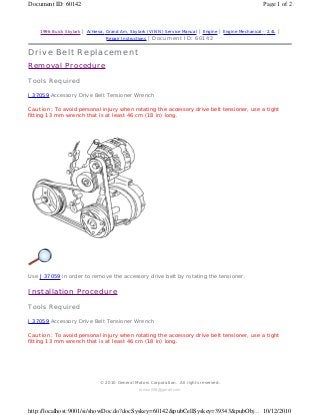
  • 2. Use J 37059 in order to install the accessory drive belt by rotating the tensioner. Page 2 of 2Document ID: 60142 10/12/2010http://localhost:9001/si/showDoc.do?docSyskey=60142&pubCellSyskey=39343&pubObj... tomsn048@gmail.com
  • 3. 1996 Buick Skylark | Achieva, Grand Am, Skylark (VIN N) Service Manual | Engine | Engine Mechanical - 2.4L | Repair Instructions | Document ID: 60815 Drive Belt Tensioner Replacement Removal Procedure 1. Disconnect the negative battery cable. Caution: Unless directed otherwise, the ignition and start switch must be in the OFF or LOCK position, and all electrical loads must be OFF before servicing any electrical component. Disconnect the negative battery cable to prevent an electrical spark should a tool or equipment come in contact with an exposed electrical terminal. Failure to follow these precautions may result in personal injury and/or damage to the vehicle or its components. in General Information. 2. Remove the accessory drive belt. Refer to Drive Belt Replacement . 3. Remove the generator assembly. Refer to Generator Replacement in Engine Electrical. 4. Raise and support the vehicle. Refer to SECTION 0A. 5. Remove the oil filter. 6. Refer to Drive Belt Idler Pulley Replacement 7. Remove the tensioner. Installation Procedure 6.1. The A/C compressor mounting bolt 6.2. The A/C compressor. Position it aside. © 2010 General Motors Corporation. All rights reserved. Page 1 of 3Document ID: 60815 10/12/2010http://localhost:9001/si/showDoc.do?docSyskey=60815&pubCellSyskey=39344&pubObj... tomsn048@gmail.com
  • 4. 1. Install the tensioner. Tighten Tighten the tensioner nut to 50 N·m (37 lb ft). 2. Refer to Drive Belt Idler Pulley Replacement Tighten Tighten the bolts to 54 N·m (40 lb ft). 2.1. The A/C compressor. Refer to SECTION 1B. 2.2. The A/C compressor mounting bolts. Refer to SECTION 1B. Page 2 of 3Document ID: 60815 10/12/2010http://localhost:9001/si/showDoc.do?docSyskey=60815&pubCellSyskey=39344&pubObj... tomsn048@gmail.com
  • 5. 3. Install the oil filter. 4. Lower the vehicle. 5. Install the generator assembly. Refer to Generator Replacement in Engine Electrical. 6. Install the drive belt. Refer to Drive Belt Replacement . 7. Connect the negative battery cable. Page 3 of 3Document ID: 60815 10/12/2010http://localhost:9001/si/showDoc.do?docSyskey=60815&pubCellSyskey=39344&pubObj... tomsn048@gmail.com
  • 6. 1996 Buick Skylark | Achieva, Grand Am, Skylark (VIN N) Service Manual | Engine | Engine Mechanical - 2.4L | Repair Instructions | Document ID: 60819 Drive Belt Idler Pulley Replacement Removal Procedure 1. Disconnect the negative battery cable. Refer to Caution: Unless directed otherwise, the ignition and start switch must be in the OFF or LOCK position, and all electrical loads must be OFF before servicing any electrical component. Disconnect the negative battery cable to prevent an electrical spark should a tool or equipment come in contact with an exposed electrical terminal. Failure to follow these precautions may result in personal injury and/or damage to the vehicle or its components. in General Information. 2. Remove the accessory drive belt. Refer to Drive Belt Replacement . 3. Remove the idler pulley bracket and bolts. 4. Remove the idler pulley. Installation Procedure Notice: Use the correct fastener in the correct location. Replacement fasteners must be the correct part number for that application. Fasteners requiring replacement or fasteners requiring the use of thread locking compound or sealant are identified in the service procedure. Do not use paints, lubricants, or corrosion inhibitors on fasteners or fastener joint surfaces unless specified. These coatings affect fastener torque and joint clamping force and may damage the fastener. Use the correct tightening sequence and specifications when installing fasteners in order to avoid damage to parts and systems. © 2010 General Motors Corporation. All rights reserved. Page 1 of 2Document ID: 60819 10/12/2010http://localhost:9001/si/showDoc.do?docSyskey=60819&pubCellSyskey=39414&pubObj... tomsn048@gmail.com
  • 7. 1. Install the idler pulley. 2. Install the idler pulley bracket and bolts. Tighten Tighten the bolts to 50 N·m (37 lb ft). 3. Install the drive belt. Refer to Drive Belt Replacement . 4. Connect the negative battery cable. Page 2 of 2Document ID: 60819 10/12/2010http://localhost:9001/si/showDoc.do?docSyskey=60819&pubCellSyskey=39414&pubObj... tomsn048@gmail.com
  • 8. 1996 Buick Skylark | Achieva, Grand Am, Skylark (VIN N) Service Manual | Engine | Engine Mechanical - 2.4L | Repair Instructions | Document ID: 60824 Engine Mount Replacement Removal Procedure Tools Required J 28467-360 Engine Support Fixture 1. Disconnect the negative battery cable. Refer to Caution: Unless directed otherwise, the ignition and start switch must be in the OFF or LOCK position, and all electrical loads must be OFF before servicing any electrical component. Disconnect the negative battery cable to prevent an electrical spark should a tool or equipment come in contact with an exposed electrical terminal. Failure to follow these precautions may result in personal injury and/or damage to the vehicle or its components. in General Information. 2. Remove the one bolt attaching the coolant recovery tank. Refer to Coolant Recovery Tank Replacement in Engine Cooling. 3. Remove the coolant recovery tank and position it aside. 4. Install the J 28467-360 and raise the engine off of the mount. 5. Remove the nuts holding the mount to the body. 6. Remove the bolts holding the engine bracket to the mount. 7. Remove the engine mount assembly. Installation Procedure Tools Required © 2010 General Motors Corporation. All rights reserved. Page 1 of 2Document ID: 60824 10/12/2010http://localhost:9001/si/showDoc.do?docSyskey=60824&pubCellSyskey=39423&pubObj... tomsn048@gmail.com
  • 9. J 28467-360 Engine Support Fixture 1. Install the engine mount assembly. 2. Install the nuts holding the mount to the body. Do not tighten. 3. Install the bolts holding the engine bracket to the mount. Tighten Notice: Use the correct fastener in the correct location. Replacement fasteners must be the correct part number for that application. Fasteners requiring replacement or fasteners requiring the use of thread locking compound or sealant are identified in the service procedure. Do not use paints, lubricants, or corrosion inhibitors on fasteners or fastener joint surfaces unless specified. These coatings affect fastener torque and joint clamping force and may damage the fastener. Use the correct tightening sequence and specifications when installing fasteners in order to avoid damage to parts and systems. 4. Remove the J 28467-360 . 5. Install the coolant recovery tank. Refer to Coolant Recover Tank Replacement in Engine Cooling. 6. Connect the negative battery cable. • Tighten the bolts holding the engine bracket to the mount to 60 N·m (44 lb ft) + 90 degrees. • Tighten the nuts holding the mount to the body to 75 N·m (55 lb ft). Page 2 of 2Document ID: 60824 10/12/2010http://localhost:9001/si/showDoc.do?docSyskey=60824&pubCellSyskey=39423&pubObj... tomsn048@gmail.com
  • 10. 1996 Buick Skylark | Achieva, Grand Am, Skylark (VIN N) Service Manual | Engine | Engine Mechanical - 2.4L | Repair Instructions | Document ID: 61738 Engine Mount Strut Replacement Removal Procedure 1. Disconnect the negative battery cable. Refer to Caution: Unless directed otherwise, the ignition and start switch must be in the OFF or LOCK position, and all electrical loads must be OFF before servicing any electrical component. Disconnect the negative battery cable to prevent an electrical spark should a tool or equipment come in contact with an exposed electrical terminal. Failure to follow these precautions may result in personal injury and/or damage to the vehicle or its components. in General Information. 2. Raise and support the vehicle. Refer to SECTION 0A. 3. Remove the right front splash shield. 4. Remove the engine mount strut bolts. 5. Remove the engine mount strut. Installation Procedure © 2010 General Motors Corporation. All rights reserved. Page 1 of 2Document ID: 61738 10/12/2010http://localhost:9001/si/showDoc.do?docSyskey=61738&pubCellSyskey=39425&pubObj... tomsn048@gmail.com
  • 11. 1. Install the engine mount strut. 2. Install the engine mount strut bolts. Tighten Tighten the strut bolts to 100 N·m (74 lb ft) + 90 degrees. Notice: Use the correct fastener in the correct location. Replacement fasteners must be the correct part number for that application. Fasteners requiring replacement or fasteners requiring the use of thread locking compound or sealant are identified in the service procedure. Do not use paints, lubricants, or corrosion inhibitors on fasteners or fastener joint surfaces unless specified. These coatings affect fastener torque and joint clamping force and may damage the fastener. Use the correct tightening sequence and specifications when installing fasteners in order to avoid damage to parts and systems. 3. Install the right front splash shield. 4. Lower the vehicle. 5. Connect the negative battery cable. Page 2 of 2Document ID: 61738 10/12/2010http://localhost:9001/si/showDoc.do?docSyskey=61738&pubCellSyskey=39425&pubObj... tomsn048@gmail.com
  • 12. 1996 Buick Skylark | Achieva, Grand Am, Skylark (VIN N) Service Manual | Engine | Engine Mechanical - 2.4L | Repair Instructions | Document ID: 60826 Intake Manifold Replacement Removal Procedure 1. Disconnect the negative battery cable. Refer to Caution: Unless directed otherwise, the ignition and start switch must be in the OFF or LOCK position, and all electrical loads must be OFF before servicing any electrical component. Disconnect the negative battery cable to prevent an electrical spark should a tool or equipment come in contact with an exposed electrical terminal. Failure to follow these precautions may result in personal injury and/or damage to the vehicle or its components. in General Information. 2. Disconnect the following electrical connectors: 3. Disconnect the vacuum hoses from the fuel regulator and the EVAP Canister Purge solenoid to the canister. 4. Remove the air cleaner duct. 5. Remove the accelerator control cable bracket. 6. Remove the stud ended generator mount bolt. • MAP sensor • Intake Air Temperature (IAT) sensor • EVAP Canister Purge solenoid • Fuel injector harness © 2010 General Motors Corporation. All rights reserved. Page 1 of 6Document ID: 60826 10/12/2010http://localhost:9001/si/showDoc.do?docSyskey=60826&pubCellSyskey=39398&pubObj... tomsn048@gmail.com
  • 13. 7. Remove the EGR pipe from the EGR adapter. 8. Raise and support the vehicle. Refer to SECTION 0A. 9. Remove the intake manifold support brace. 10. Lower the vehicle. Page 2 of 6Document ID: 60826 10/12/2010http://localhost:9001/si/showDoc.do?docSyskey=60826&pubCellSyskey=39398&pubObj... tomsn048@gmail.com
  • 14. 11. Remove the intake manifold retaining nuts and bolts. 12. Remove the intake manifold and the gasket. Installation Procedure Important: The engine and the manifold should be at ambient temperature when assembled. Do not attempt to install a cold manifold on a hot engine. 1. Install the intake manifold and the gasket. If the gasket is damaged, install a new one with the stamped numbers facing towards the manifold surface. Page 3 of 6Document ID: 60826 10/12/2010http://localhost:9001/si/showDoc.do?docSyskey=60826&pubCellSyskey=39398&pubObj... tomsn048@gmail.com
  • 15. 2. Install the intake manifold fasteners. Tighten Tighten the fasteners to 24 N·m (18 lb ft). Notice: Use the correct fastener in the correct location. Replacement fasteners must be the correct part number for that application. Fasteners requiring replacement or fasteners requiring the use of thread locking compound or sealant are identified in the service procedure. Do not use paints, lubricants, or corrosion inhibitors on fasteners or fastener joint surfaces unless specified. These coatings affect fastener torque and joint clamping force and may damage the fastener. Use the correct tightening sequence and specifications when installing fasteners in order to avoid damage to parts and systems. 3. Raise and suitably support the vehicle. Refer to SECTION 0A. Page 4 of 6Document ID: 60826 10/12/2010http://localhost:9001/si/showDoc.do?docSyskey=60826&pubCellSyskey=39398&pubObj... tomsn048@gmail.com
  • 16. 4. Install the intake manifold brace. Finger start all bolts. Tighten 5. Lower the vehicle. 6. Connect the EGR pipe to the EGR adapter. 7. Install the EGR pipe to the EGR adapter fasteners. Tighten Tighten the fasteners to 26 N·m (19 lb ft). • Tighten bolt (A) to 24 N·m (18 lb ft). • Tighten bolt (B) to 26 N·m (19 lb ft). Page 5 of 6Document ID: 60826 10/12/2010http://localhost:9001/si/showDoc.do?docSyskey=60826&pubCellSyskey=39398&pubObj... tomsn048@gmail.com
  • 17. 8. Install the stud ended generator mount bolt. 9. Install the accelerator control cable bracket. 10. Connect the vacuum hoses to the fuel regulator and to the EVAP canister purge solenoid. Important: If the Intake Air Temperature (IAT) sensor is removed, apply sealant GM P/N 1052080 or equivalent to its threads before installation. 11. Connect the following electrical connections: 12. Install the air cleaner duct. 13. Connect the negative battery cable. • MAP sensor • IAT sensor • EVAP canister purge solenoid • Fuel injector harness Page 6 of 6Document ID: 60826 10/12/2010http://localhost:9001/si/showDoc.do?docSyskey=60826&pubCellSyskey=39398&pubObj... tomsn048@gmail.com
  • 18. 1996 Buick Skylark | Achieva, Grand Am, Skylark (VIN N) Service Manual | Engine | Engine Mechanical - 2.4L | Repair Instructions | Document ID: 60838 Exhaust Manifold Replacement Removal Procedure 1. Disconnect the negative battery cable. Refer to Caution: Unless directed otherwise, the ignition and start switch must be in the OFF or LOCK position, and all electrical loads must be OFF before servicing any electrical component. Disconnect the negative battery cable to prevent an electrical spark should a tool or equipment come in contact with an exposed electrical terminal. Failure to follow these precautions may result in personal injury and/or damage to the vehicle or its components. in General Information. 2. Disconnect the O2S (Oxygen) sensor connector. 3. Raise and support the vehicle. Refer to SECTION 0A. 4. Remove the exhaust manifold brace to manifold fasteners. © 2010 General Motors Corporation. All rights reserved. Page 1 of 6Document ID: 60838 10/12/2010http://localhost:9001/si/showDoc.do?docSyskey=60838&pubCellSyskey=39364&pubObj... tomsn048@gmail.com
  • 19. 5. Remove the upper heat shield. Notice: Do not bend the exhaust flex decoupler more than 3 degrees in any direction. Movement of more than 3 degrees will damage the exhaust flex decoupler. 6. Remove the manifold to the exhaust flex decoupler fasteners. Page 2 of 6Document ID: 60838 10/12/2010http://localhost:9001/si/showDoc.do?docSyskey=60838&pubCellSyskey=39364&pubObj... tomsn048@gmail.com
  • 20. 7. Pull down and back on the exhaust pipe to disengage it from the exhaust manifold. 8. Lower the vehicle. 9. Remove the exhaust manifold to cylinder head retaining nuts. 10. Remove the exhaust manifold, seals and gaskets. 11. Clean all sealing surfaces. Installation Procedure 1. Install a new exhaust manifold gasket. 2. Install the exhaust manifold. Page 3 of 6Document ID: 60838 10/12/2010http://localhost:9001/si/showDoc.do?docSyskey=60838&pubCellSyskey=39364&pubObj... tomsn048@gmail.com
  • 21. 3. Install the exhaust manifold nuts. Tighten Tighten the nuts to 13 N·m (110 lb in). Notice: Use the correct fastener in the correct location. Replacement fasteners must be the correct part number for that application. Fasteners requiring replacement or fasteners requiring the use of thread locking compound or sealant are identified in the service procedure. Do not use paints, lubricants, or corrosion inhibitors on fasteners or fastener joint surfaces unless specified. These coatings affect fastener torque and joint clamping force and may damage the fastener. Use the correct tightening sequence and specifications when installing fasteners in order to avoid damage to parts and systems. 4. Raise and support the vehicle. Refer to SECTION 0A. Page 4 of 6Document ID: 60838 10/12/2010http://localhost:9001/si/showDoc.do?docSyskey=60838&pubCellSyskey=39364&pubObj... tomsn048@gmail.com
  • 22. 5. Install the heat shield. Tighten Tighten the bolts to 14 N·m (124 lb in). 6. Install the exhaust manifold brace to exhaust manifold fasteners. Tighten • Tighten the bolt to 56 N·m (41 lb ft). • Tighten the nuts to 26 N·m (19 lb ft). Page 5 of 6Document ID: 60838 10/12/2010http://localhost:9001/si/showDoc.do?docSyskey=60838&pubCellSyskey=39364&pubObj... tomsn048@gmail.com
  • 23. 7. Install the manifold to the flex decoupler fasteners. Tighten Tighten the fasteners to 35 N·m (26 lb ft). 8. Lower the vehicle. 9. Coat the threads of the O2S (Oxygen sensor) connector with anti-seize compound GM P/N 5613695 or equivalent. 10. Connect the O2S (Oxygen sensor) connector. 11. Connect the negative battery cable. Page 6 of 6Document ID: 60838 10/12/2010http://localhost:9001/si/showDoc.do?docSyskey=60838&pubCellSyskey=39364&pubObj... tomsn048@gmail.com
  • 24. 1996 Buick Skylark | Achieva, Grand Am, Skylark (VIN N) Service Manual | Engine | Engine Mechanical - 2.4L | Repair Instructions | Document ID: 61378 Intake Camshaft, Housing and Lifter Replacement Removal Procedure Tools Required Important: 1. Disconnect the negative battery cable. Refer to Caution: Unless directed otherwise, the ignition and start switch must be in the OFF or LOCK position, and all electrical loads must be OFF before servicing any electrical component. Disconnect the negative battery cable to prevent an electrical spark should a tool or equipment come in contact with an exposed electrical terminal. Failure to follow these precautions may result in personal injury and/or damage to the vehicle or its components. in General Information. 2. Remove the ignition coil and the module assembly electrical connections. 3. Remove the ignition coil and the module assembly to the camshaft housing bolts. • J 36660-A Torque Angle Meter • J 36011 Spark Plug Connector Assembly Remover • Any time the camshaft housing to the cylinder head bolts are loosened or removed, the camshaft housing to the cylinder head gasket must be replaced. • During disassembly, ensure that the valve lifters are kept together and identified so that they can be reinstalled in the original locations. • Before disassembling the valve mechanism, make a compression test and note the results. Refer to Engine Compression Test . © 2010 General Motors Corporation. All rights reserved. Page 1 of 9Document ID: 61378 10/12/2010http://localhost:9001/si/showDoc.do?docSyskey=61378&pubCellSyskey=39491&pubObj... tomsn048@gmail.com
  • 25. 4. Remove the assembly by pulling straight up. 5. Use the J 36011 in order to remove the connector assembly if stuck to the spark plugs. Use the tool by first twisting then pulling up on the connector assembly. 6. Remove the camshaft position sensor connector. 7. Remove the power steering pump and position aside. Do not disconnect the power steering lines. 8. Remove the vacuum line from the fuel pressure regulator and the fuel injector harness connector. 9. Remove the fuel line retaining clamp from the bracket on top of the intake camshaft housing. 10. Remove the fuel rail to the camshaft housing retaining bolts. Page 2 of 9Document ID: 61378 10/12/2010http://localhost:9001/si/showDoc.do?docSyskey=61378&pubCellSyskey=39491&pubObj... tomsn048@gmail.com
  • 26. 11. Remove the fuel rail from the cylinder head as follows: 12. Disconnect, but do not remove from the vehicle, the timing chain housing at the intake camshaft housing. Refer to Timing Chain Housing Replacement . 13. Remove the camshaft housing cover to the camshaft housing retaining bolts. Important: • Cover the injector openings in the cylinder head. • Cover the injector nozzles. • Leave the fuel lines attached and the position fuel rail aside (on top of the master cylinder). • Use the reverse of the tightening procedure when loosening the camshaft housing to the cylinder head retaining bolts. Page 3 of 9Document ID: 61378 10/12/2010http://localhost:9001/si/showDoc.do?docSyskey=61378&pubCellSyskey=39491&pubObj... tomsn048@gmail.com
  • 27. 14. Remove the camshaft housing to the cylinder head retaining bolts. Important: Tighten the bolts evenly in order to prevent the cover from binding on the dowel pins. 15. Push the cover off the housing by threading four of the housing to head retaining bolts into the tapped holes in the camshaft housing cover. 16. Remove the two loosely installed camshaft housing to head bolts. 17. Remove the cover and discard the gaskets. 18. Loosely reinstall one camshaft housing to cylinder head bolt in order to retain the housing during the camshaft and lifter removal. 19. Note the position of the chain sprocket dowel pin for reassembly. Remove the camshaft being careful not to damage the camshaft or the journals. Important: The valve lifters are not serviceable. Replace faulty valve lifters. Coat the valve lifter with the Camshaft and Lifter Prelube GM P/N 12345501 or the equivalent. If the new lifters are installed, add the Engine Oil Supplement GM P/N 1052367, or the equivalent, to the engine oil. 20. Remove the valve lifters as follows: Important: Ensure that the alignment dowel pins are in the cylinder head prior to installing the camshaft housing. • Leave the two bolts loosely in place in order to hold the camshaft housing while separating the camshaft cover from the housing. • Keep the lifters in order to reinstall the lifters to the original locations. • In order to minimize the lifter bleed down, perform the following procedure: - Store the lifters upside down, opposite of the installed position, on a level surface. - Store the lifters submerged in clean engine oil. Page 4 of 9Document ID: 61378 10/12/2010http://localhost:9001/si/showDoc.do?docSyskey=61378&pubCellSyskey=39491&pubObj... tomsn048@gmail.com
  • 28. 21. Remove the camshaft housing and the gasket. Important: Do not attempt to repair the camshaft, replace if damaged. If a new camshaft is installed, all of the valve lifters actuated by the camshaft must also be replaced. 22. Inspect the following camshaft components for damage: 23. Inspect the camshaft bearing surfaces and the camshaft lobes for the following damage: Important: 24. Measure the bearing journals diameter with a micrometer. If out of specification, replace the camshaft. Installation Procedure • The sprocket • The keyway and the threads • The camshaft position sensor reluctor • Wear • Galling • Gouges • Overheating or discoloration • If a new camshaft has been installed, add the Engine Oil Supplement GM P/N 1052367 or the equivalent to the engine oil. • Coat the entire camshaft with the Camshaft and Lifter Prelube GM P/N 12345501 or the equivalent. Page 5 of 9Document ID: 61378 10/12/2010http://localhost:9001/si/showDoc.do?docSyskey=61378&pubCellSyskey=39491&pubObj... tomsn048@gmail.com
  • 29. 1. Install the camshaft housing to the cylinder head with a new gasket. Sealer is unnecessary. 2. Loosely install on camshaft housing to the cylinder head bolt in order to hold the housing in place. Notice: The camshaft lobes and the journals must be adequately lubricated or serious engine damage will occur upon start up. Important: Used lifters must be returned to the original position in the camshaft housing. If the camshaft is being replaced, the lifters actuated by the camshaft must also be replaced. 3. Install the lifters into the lifter bores. 4. Install the camshaft in the same position as when removed. The timing chain sprocket dowel pin should be straight up and line up with the centerline of the lifter bores. 5. Install the new camshaft housing to the green colored camshaft housing cover seals and into the cover. Sealant is unnecessary. 6. Remove the bolt holding the housing in place. 7. Apply the pipe sealant GM P/N 1052080 or the equivalent to the camshaft housing and the cover retaining bolt threads. 8. Install the camshaft housing cover to the camshaft housing. Important: The top intake camshaft housing bolts are tightened to a different specification Page 6 of 9Document ID: 61378 10/12/2010http://localhost:9001/si/showDoc.do?docSyskey=61378&pubCellSyskey=39491&pubObj... tomsn048@gmail.com
  • 30. than the other camshaft housing bolts. 9. Using the J 36660-A , install and tighten the bolts. Tighten Notice: Use the correct fastener in the correct location. Replacement fasteners must be the correct part number for that application. Fasteners requiring replacement or fasteners requiring the use of thread locking compound or sealant are identified in the service procedure. Do not use paints, lubricants, or corrosion inhibitors on fasteners or fastener joint surfaces unless specified. These coatings affect fastener torque and joint clamping force and may damage the fastener. Use the correct tightening sequence and specifications when installing fasteners in order to avoid damage to parts and systems. 10. Rotate the bolts the amount of degrees specified in sequence. 11. Install the timing chain housing and the timing chain. Refer to Timing Chain Housing Replacement . 12. Uncover the fuel injectors and install the new injector O-ring seals. Lubricate the O-ring seals with engine oil. • Tighten the camshaft housing to cylinder head bolts to 15 N·m (11 lb ft) + 90 degrees. • Tighten the camshaft housing cover to camshaft housing bolts to 15 N·m (11 lb ft) + 30 degrees. Page 7 of 9Document ID: 61378 10/12/2010http://localhost:9001/si/showDoc.do?docSyskey=61378&pubCellSyskey=39491&pubObj... tomsn048@gmail.com
  • 31. 13. Uncover the injector openings in the cylinder head and install the fuel rail onto the cylinder head. 14. Install the fuel rail to the camshaft housing bolts. Tighten Tighten the camshaft housing bolts to 26 N·m (19 lb ft). 15. Install the fuel line retaining clamp and the retainer to the bracket on top of the camshaft housing. 16. Install the vacuum line to the fuel pressure regulator. 17. Install the fuel injector harness connector. 18. Install the camshaft position sensor connector. Important: When reinstalling the power steering pump, apply a 3 mm bead of GM P/N 12346286 sealer or the equivalent to the joint at the end of the camshaft housing halves before the installation of the power steering pump and the pump face seal. Page 8 of 9Document ID: 61378 10/12/2010http://localhost:9001/si/showDoc.do?docSyskey=61378&pubCellSyskey=39491&pubObj... tomsn048@gmail.com
  • 32. 19. Install the power steering pump assembly. 20. Reinstall any spark plug boot connector assembly that has stuck to a spark plug back onto the ignition coil and module assembly. 21. Locate the ignition coil and the module assembly over the spark plugs and push straight down. 22. Clean any loose lubricant that is present on the ignition coil and the module assembly to the camshaft housing bolts. 23. Apply pipe sealant GM P/N 1052080 or the equivalent onto the ignition coil and the module cover assembly to the camshaft housing bolts. Tighten Tighten the bolts to 15 N·m (11 lb ft) + 30 degrees. Important: Do not compress the lifter plungers using a vise or other tool. This will cause more air to enter the lifter assembly and will take more time to bleed out once the lifters are installed. 24. If new lifters have been installed or the lifters bled down while the engine was disassembled, excessive lifter noise may be experienced. This is a normal condition and no engine damage is occurring. Use the following procedure to purge air from the lifters: 25. Install the electrical connector to the ignition coil and the module assembly. 26. Connect the negative battery cable. 24.1. Start the engine and allow the engine to warm up at idle for 5 minutes. 24.2. Increase the engine speed to 2000 RPM until the lifter noise is gone. 24.3. Return the engine to idle for an additional 5 minutes or perform a road test. Page 9 of 9Document ID: 61378 10/12/2010http://localhost:9001/si/showDoc.do?docSyskey=61378&pubCellSyskey=39491&pubObj... tomsn048@gmail.com
  • 33. 1996 Buick Skylark | Achieva, Grand Am, Skylark (VIN N) Service Manual | Engine | Engine Mechanical - 2.4L | Repair Instructions | Document ID: 61489 Exhaust Camshaft, Housing and Lifter Replacement Removal Procedure Tools Required Important: Any time the camshaft housing to cylinder head bolts are loosened or removed, the camshaft housing to cylinder head gasket must be replaced. During disassembly, ensure that the valve lifters are kept together and identified so that they can be reinstalled in the original locations. Before disassembling the valve mechanism, make a compression test and note the results. Refer to Engine Compression Test . 1. Disconnect the negative battery cable. 2. Remove the ignition coil and the module assembly electrical connection. 3. Remove the ignition coil and the module assembly to the camshaft housing bolts and remove the assembly by pulling straight up. 4. Use the J 36011 in order to remove the connector assembly if stuck to the spark plugs. Use the tool by first twisting then pulling upward on the connector assembly. 5. Remove the electrical connection from the oil pressure switch. 6. For vehicles equipped with automatic transmission, remove the transmission fluid level indicator tube assembly from the exhaust camshaft cover and the position aside. • J 36660-A Torque Angle Meter • J 36011 Spark Plug Connector Assembly Remover © 2010 General Motors Corporation. All rights reserved. Page 1 of 7Document ID: 61489 10/12/2010http://localhost:9001/si/showDoc.do?docSyskey=61489&pubCellSyskey=39492&pubObj... tomsn048@gmail.com
  • 34. 7. Disconnect the timing chain housing at the exhaust camshaft housing but do not remove from the parts from the vehicle. Refer to Timing Chain Housing Replacement . 8. Remove the exhaust camshaft cover and the gasket. 9. Remove the exhaust camshaft housing to the cylinder head bolts. Page 2 of 7Document ID: 61489 10/12/2010http://localhost:9001/si/showDoc.do?docSyskey=61489&pubCellSyskey=39492&pubObj... tomsn048@gmail.com
  • 35. 10. Use the reverse of the tightening procedure when loosening the camshaft housing to the cylinder head retaining bolts. 11. Leave two bolts loosely in place in order to hold the camshaft housing while separating the camshaft cover from the housing. Important: Tighten the bolts in evenly in order to prevent the cover from binding on the dowel pins. 12. Push the cover off the housing by threading the four of the housing to head retaining bolts into the tapped holes in the camshaft cover. 13. Remove the two loosely installed camshaft housing to head bolts. 14. Remove the cover. 15. Discard the gaskets. 16. Loosely reinstall the one camshaft housing to the cylinder head bolt in order to retain the housing during the camshaft and the lifter removal. 17. Notice the position of the chain sprocket dowel pin for reassembly. Remove the camshaft carefully in order to prevent damage to the camshaft or the journals. 18. Remove the valve lifters. Keep the lifters in order so that the lifters can be reinstalled in the original location. Important: 19. In order to minimize lifter bleed down, use the following procedure: Important: Ensure that the camshaft housing alignment dowel pins are in the cylinder head • These lifters are not serviceable. Replace any faulty lifters. • Coat the lifter with Camshaft and Lifter Prelube GM P/N 12345501 or the equivalent. If new lifters are installed, add the Engine Oil Supplement GM P/N 1052367 or the equivalent to the engine oil. • Store lifters upside down (the camshaft contact surface down) on a level surface. • Store the lifters submerged in clean engine oil. Page 3 of 7Document ID: 61489 10/12/2010http://localhost:9001/si/showDoc.do?docSyskey=61489&pubCellSyskey=39492&pubObj... tomsn048@gmail.com
  • 36. prior to installing the housing. 20. Remove the camshaft housing gasket. Installation Procedure 1. Install the camshaft housing to the cylinder head with a new gasket. Sealer is unnecessary. Page 4 of 7Document ID: 61489 10/12/2010http://localhost:9001/si/showDoc.do?docSyskey=61489&pubCellSyskey=39492&pubObj... tomsn048@gmail.com
  • 37. 2. Loosely install one camshaft housing to the cylinder head bolt in order to hold the housing in place. Important: 3. Install the lifters into the lifter bores. Notice: The camshaft lobes and the journals must be adequately lubricated or serious engine damage will occur upon start up. 4. Lube the camshaft lobes and the journals with the Camshaft and Lifter Prelube GM P/N 12345501 or the equivalent. 5. Install the camshaft in the same position as when removed. The timing chain sprocket dowel pin should be straight up and line up with the centerline of the lifter bores. 6. Install the new camshaft housing to the orange camshaft housing cover seals into the cover. Sealer is unnecessary. 7. Remove the bolt holding the housing in place. 8. Apply pipe sealant GM P/N 1052080 or the equivalent to the camshaft housing and the cover retaining bolt threads. 9. Install the camshaft housing cover to the camshaft housing. • Used lifters must be returned to their original position in the camshaft housing. • If the camshaft is being replaced, the lifters must also be replaced. Page 5 of 7Document ID: 61489 10/12/2010http://localhost:9001/si/showDoc.do?docSyskey=61489&pubCellSyskey=39492&pubObj... tomsn048@gmail.com
  • 38. 10. Use the J 36660-A , in order to install the bolts. Tighten Notice: Use the correct fastener in the correct location. Replacement fasteners must be the correct part number for that application. Fasteners requiring replacement or fasteners requiring the use of thread locking compound or sealant are identified in the service procedure. Do not use paints, lubricants, or corrosion inhibitors on fasteners or fastener joint surfaces unless specified. These coatings affect fastener torque and joint clamping force and may damage the fastener. Use the correct tightening sequence and specifications when installing fasteners in order to avoid damage to parts and systems. 11. Install the timing chain housing to camshaft housing and the timing chain. Refer to Timing Chain Housing Replacement . 12. Install the exhaust camshaft housing cover and the new gasket. 13. Install the transmission fluid level indicator tube assembly to the exhaust camshaft cover. 14. Install the electrical connection to the oil pressure switch. 15. Reinstall any spark plugs boot connector assembly that stuck to a spark plug, back onto the ignition coil and module assembly. • Tighten the camshaft housing to cylinder head bolts to 15 N·m (11 lb ft) + 90 degrees. • Tighten the camshaft housing cover to camshaft housing bolts to 15 N·m (11 lb ft) + 30 degrees. Page 6 of 7Document ID: 61489 10/12/2010http://localhost:9001/si/showDoc.do?docSyskey=61489&pubCellSyskey=39492&pubObj... tomsn048@gmail.com
  • 39. 16. Locate the ignition coil and the module assembly over the spark plugs. 17. Push straight down. 18. Clean any lubricant that is present on the ignition coil and the module assembly to the camshaft housing bolts. 19. Apply Pipe Sealant GM P/N 1052080 or the equivalent onto the ignition coil and the module assembly to the camshaft housing bolts. Tighten Tighten the bolts to 15 N·m (11 lb ft) + 30 degrees. 20. Install the electrical connector to the ignition coil and the module assembly. 21. Connect the negative battery cable. Important: Do not compress the lifter plungers using a vise or other tool. This will cause more air to enter the lifter assembly and will take more time to bleed out once the lifters are installed. 22. If new lifters have been installed or the lifters bled down while the engine was disassembled excessive lifter noise may be experienced. This is a normal condition and no engine damage is occurring. Use the following procedure in order to purge the air from the lifters: 23. Start the engine and inspect for leaks. 22.1. Start the engine and allow to warm up at the idle for 5 minutes. 22.2. Increase the engine speed to 2000 RPM until the lifter noise is gone. 22.3. Return the engine to idle for an additional 5 minutes or perform a road test. Page 7 of 7Document ID: 61489 10/12/2010http://localhost:9001/si/showDoc.do?docSyskey=61489&pubCellSyskey=39492&pubObj... tomsn048@gmail.com
  • 40. 1996 Buick Skylark | Achieva, Grand Am, Skylark (VIN N) Service Manual | Engine | Engine Mechanical - 2.4L | Repair Instructions | Document ID: 61743 Camshaft Housing Oil Gallery Plugs Replacement Removal Procedure Tools Required J 37868 Oil Gallery Plug Installer 1. Disconnect the negative battery cable. Refer to Caution: Unless directed otherwise, the ignition and start switch must be in the OFF or LOCK position, and all electrical loads must be OFF before servicing any electrical component. Disconnect the negative battery cable to prevent an electrical spark should a tool or equipment come in contact with an exposed electrical terminal. Failure to follow these precautions may result in personal injury and/or damage to the vehicle or its components. in General Information. 2. Remove the camshaft housing. Refer to Intake Camshaft, Housing and Lifter Replacement , for the intake camshaft housing. Refer to Exhaust Camshaft, Housing and Lifter Replacement , for the exhaust camshaft housing. 3. Disassemble the oil gallery plug as follows: 3.1. Using a 8.33 mm (21/64 in) bit, drill the oil gallery plug. 3.2. With a 10.0 mm (0.3937 in) bottoming tap, thread the plug. 3.3. Install a 10.0 mm bolt into the plug and pull the plug out.© 2010 General Motors Corporation. All rights reserved. Page 1 of 2Document ID: 61743 10/12/2010http://localhost:9001/si/showDoc.do?docSyskey=61743&pubCellSyskey=39430&pubObj... tomsn048@gmail.com
  • 41. 4. Clean the oil gallery plug hole. Installation Procedure 1. Assemble the oil gallery plug with the J 37868 . 2. Install the camshaft housing. Refer to Intake Camshaft, Housing and Lifter Replacement , for the intake camshaft housing. Refer to Exhaust Camshaft, Housing and Lifter Replacement , for the exhaust camshaft housing. 3. Connect the negative battery cable. Page 2 of 2Document ID: 61743 10/12/2010http://localhost:9001/si/showDoc.do?docSyskey=61743&pubCellSyskey=39430&pubObj... tomsn048@gmail.com
  • 42. 1996 Buick Skylark | Achieva, Grand Am, Skylark (VIN N) Service Manual | Engine | Engine Mechanical - 2.4L | Repair Instructions | Document ID: 61492 Valve Stem Oil Seal and Valve Spring Replacement (Intake) Removal Procedure Tools Required Important: Any time the camshaft housing to the cylinder head bolts are loosened or removed, the camshaft housing to the cylinder head gasket must be replaced. 1. Disconnect the negative battery cable. Refer to Caution: Unless directed otherwise, the ignition and start switch must be in the OFF or LOCK position, and all electrical loads must be OFF before servicing any electrical component. Disconnect the negative battery cable to prevent an electrical spark should a tool or equipment come in contact with an exposed electrical terminal. Failure to follow these precautions may result in personal injury and/or damage to the vehicle or its components. in General Information. 2. Disconnect the ignition coil and module assembly electrical connections. 3. Remove the ignition coil and module assembly to the camshaft housing bolts. Remove the assembly by pulling straight up. Use the J 36011 in order to remove the connector assembly • J 36588 Valve Spring Compressor T-Bolt • J 5892-D Valve Spring Depressor • J 36011 Spark Plug Connector Assembly Remover • J 36017 Valve Guide Seal Remover • J 36660-A Torque Angle Meter © 2010 General Motors Corporation. All rights reserved. Page 1 of 8Document ID: 61492 10/12/2010http://localhost:9001/si/showDoc.do?docSyskey=61492&pubCellSyskey=39394&pubObj... tomsn048@gmail.com
  • 43. if it is stuck to the spark plugs. Use the tool by first twisting then pulling up on the connector assembly. 4. Remove the camshaft position sensor connector. 5. Remove the power steering pump. Refer to SECTION 3B1. 6. Disconnect the vacuum line from the fuel pressure regulator and the fuel injector harness connector. 7. Remove the fuel line retaining clamp from the bracket on top of the intake camshaft housing. 8. Remove the fuel rail to the camshaft housing retaining bolts. 9. Remove the fuel rail from the cylinder head. 10. Cover the injector openings in the cylinder head. 11. Cover the injector nozzles. 12. Leave the fuel lines attached and position the fuel rail aside (on top of the master cylinder). 13. Disconnect the timing chain housing at the intake camshaft housing but do not remove from Page 2 of 8Document ID: 61492 10/12/2010http://localhost:9001/si/showDoc.do?docSyskey=61492&pubCellSyskey=39394&pubObj... tomsn048@gmail.com
  • 44. the vehicle. Refer to Timing Chain Housing Replacement . 14. Remove the camshaft to cylinder head retaining bolts. Notice: Turn the camshaft housing upside down as soon as it is removed from the cylinder head. The lifters will fall out of the camshaft housing if it is not turned upside down. the lifters can be damaged if they fall out and hit a hard surface. Important: Use the reverse of the tightening procedure when loosening the camshaft housing to the cylinder head retaining bolts. 15. Remove the camshaft housing. 16. Remove the camshaft housing gasket. 17. Remove the spark plug. 18. Using a suitable adapter, apply air pressure to the cylinder. Page 3 of 8Document ID: 61492 10/12/2010http://localhost:9001/si/showDoc.do?docSyskey=61492&pubCellSyskey=39394&pubObj... tomsn048@gmail.com
  • 45. 19. Compress the valve spring. Use the J 5892-D and the J 36588 . 20. Disassemble the following components: 21. Assemble the following components: 22. Inspect for proper valve key seating. Installation Procedure 1. Remove air line adapter. 2. Install the spark plug. Notice: Carefully roll the camshaft housing right side up as it is installed onto the cylinder head. The lifters can be damaged if they fall out and hit a hard surface. • The valve keys • The retainer • The spring • The valve seal using J 36017 • The rotator (intake) • The valve spring seat (exhaust) • The rotator (intake) • The valve spring seat (exhaust) • A new, clean and dry valve seal. Push the seal on by hand in order to ensure that the seal is fully seated. • The spring and retainer. Use the J 5892-D , and the J 36588 in order to compress the valve spring. • The valve keys. Page 4 of 8Document ID: 61492 10/12/2010http://localhost:9001/si/showDoc.do?docSyskey=61492&pubCellSyskey=39394&pubObj... tomsn048@gmail.com
  • 46. 3. Install the camshaft housing. 4. Install the camshaft housing gasket. 5. Apply Pipe Sealant GM P/N 1052080 or equivalent to the camshaft housing retaining bolt threads. 6. Install the camshaft housing bolts. 7. Using the J 36660-A , install the bolts in sequence. Tighten Tighten the bolts to 15 N·m (11 lb ft) + 90 degrees. Notice: Use the correct fastener in the correct location. Replacement fasteners must be the correct part number for that application. Fasteners requiring replacement or fasteners requiring the use of thread locking compound or sealant are identified in the service Page 5 of 8Document ID: 61492 10/12/2010http://localhost:9001/si/showDoc.do?docSyskey=61492&pubCellSyskey=39394&pubObj... tomsn048@gmail.com
  • 47. procedure. Do not use paints, lubricants, or corrosion inhibitors on fasteners or fastener joint surfaces unless specified. These coatings affect fastener torque and joint clamping force and may damage the fastener. Use the correct tightening sequence and specifications when installing fasteners in order to avoid damage to parts and systems. 8. Install the timing chain housing and the timing chain. Refer to Timing Chain Housing Replacement . 9. Uncover the fuel injectors. 10. Install new injector O ring seals. Lubricate the O ring seals with engine oil. 11. Uncover the injector openings in the cylinder head and install the fuel rail onto the cylinder head. 12. Install the fuel rail to the camshaft housing bolts. Tighten Tighten the bolts to 26 N·m (19 lb ft). 13. Connect the fuel line retaining clamp and the retainer to the bracket on top of the camshaft housing. 14. Connect the vacuum line to the fuel pressure regulator. 15. Install the fuel injector harness connector. 16. Install the camshaft position sensor connector. Important: When reinstalling the power steering pump, apply a 3 mm bead of GM P/N 12346286 sealer or equivalent to the joint at the end of the camshaft housing halves before installation of the power steering pump and the pump face seal. Page 6 of 8Document ID: 61492 10/12/2010http://localhost:9001/si/showDoc.do?docSyskey=61492&pubCellSyskey=39394&pubObj... tomsn048@gmail.com
  • 48. 17. Install the power steering pump assembly. Refer to SECTION 3B1. 18. Reinstall any spark plug boot connector assembly that stuck to a spark plug back onto the ignition coil and module assembly. 19. Place the ignition coil and module assembly over the spark plugs and push straight down. 20. Clean any lubricant that is present on the ignition coil and module assembly to the camshaft housing bolts. 21. Apply Pipe Sealant GM P/N 1052080 or equivalent onto the ignition coil and module cover assembly to the camshaft housing bolts. Tighten Tighten the bolts to 15 N·m (11 lb ft) + 30 degrees. 22. Connect the electrical connector to the ignition coil and module assembly. Page 7 of 8Document ID: 61492 10/12/2010http://localhost:9001/si/showDoc.do?docSyskey=61492&pubCellSyskey=39394&pubObj... tomsn048@gmail.com
  • 49. Thank you very much for your reading. Please Click Here Then Get More Information.