Simulation Of Interline Power Flow Controller in Power Transmission System
•
1 like•1,531 views

The interline power flow controller (IPFC) is one of the latest generation flexible AC transmission systems (FACTS) controller used to control power flows of multiple transmission lines. The IPFC is the multifunction device, such as power flow control, voltage control, oscillation damping. This paper presents an overview and study and mathematical model of Interline Power Flow Control. The simulations of a simple power system of 500kV/230kV in MATLAB and simulation results are carried out on it. The results without and with IPFC are compared in terms of voltages, active and reactive power flows to demonstrate the performance of the IPFC model.

Recommended
Recommended
More Related Content
What's hot
What's hot (20)
Similar to Simulation Of Interline Power Flow Controller in Power Transmission System
Similar to Simulation Of Interline Power Flow Controller in Power Transmission System (20)
More from ijsrd.com
More from ijsrd.com (20)
Recently uploaded
Recently uploaded (20)
Simulation Of Interline Power Flow Controller in Power Transmission System
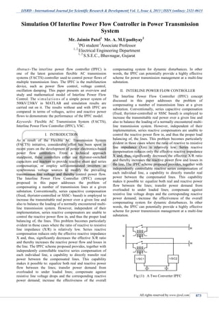
- 1. IJSRD - International Journal for Scientific Research & Development| Vol. 1, Issue 4, 2013 | ISSN (online): 2321-0613 All rights reserved by www.ijsrd.com 873 Abstract--The interline power flow controller (IPFC) is one of the latest generation flexible AC transmission systems (FACTS) controller used to control power flows of multiple transmission lines. The IPFC is the multifunction device, such as power flow control, voltage control, oscillation damping. This paper presents an overview and study and mathematical model of Interline Power Flow Control. The s i mul a t io n s of a simple power system of 500kV/230kV in MATLAB and simulation results are carried out on it. The results without and with IPFC are compared in terms of voltages, active and reactive power flows to demonstrate the performance of the IPFC model. Keywords: Flexible AC Transmission System (FACTS), Interline Power Flow Controller (IPFC), VSC. INTRODUCTIONI. As a result of the Flexible AC Transmission System (FACTS) initiative, considerable effort has been spent in recent years on the development of power electronics-based power flow controllers. From a technical approach standpoint, these controllers either use thyristor-switched capacitors and reactors to provide reactive shunt and series compensation, or employ self-commutated inverters as synchronous voltage sources to modify the prevailing transmission line voltage and thereby control power flow. The Interline Power Flow Controller (IPFC) concept proposed in this paper addresses the problem of compensating a number of transmission lines at a given substation. Conventionally, series capacitive compensation (fixed, thyristor-controlled or SSSC- based) is employed to increase the transmittable real power over a given line and also to balance the loading of a normally encountered multi- line transmission system. However, independent of their implementation, series reactive compensators are unable to control the reactive power flow in, and thus the proper load balancing of, the lines. This problem becomes particularly evident in those cases where the ratio of reactive to resistive line impedance (X/R) is relatively low. Series reactive compensation reduces only the effective reactive impedance X and, thus, significantly decreases the effective X/R ratio and thereby increases the reactive power flow and losses in the line. The IPFC scheme proposed provides, together with independently controllable reactive series compensation of each individual line, a capability to directly transfer real power between the compensated lines. This capability makes it possible to: equalize both real and reactive power flow between the lines; transfer power demand from overloaded to under loaded lines; compensate against resistive line voltage drops and the corresponding reactive power demand; increase the effectiveness of the overall compensating system for dynamic disturbances. In other words, the IPFC can potentially provide a highly effective scheme for power transmission management at a multi-line substation. INTERLINE POWER FLOW CONTROLLERII. The Interline Power Flow Controller (IPFC) concept discussed in this paper addresses the problem of compensating a number of transmission lines at a given substation. Conventionally, series capacitive compensation (fixed, thyristor-controlled or SSSC based) is employed to increase the transmittable real power over a given line and also to balance the loading of a normally encountered multi- line transmission system. However, independent of their implementation, series reactive compensators are unable to control the reactive power flow in, and thus the proper load balancing of, the lines. This problem becomes particularly evident in those cases where the ratio of reactive to resistive line impedance (Xm) is relatively low. Series reactive compensation reduces only the effective reactive impedance X and, thus, significantly decreases the effective X/R ratio and thereby increases the reactive power flow and losses in the line. The IPFC scheme proposed provides, together with independently controllable reactive series compensation of each individual line, a capability to directly transfer real power between the compensated lines. This capability makes it possible to: equalize both real and reactive power flow between the lines; transfer power demand from overloaded to under loaded lines; compensate against resistive line voltage drops and the corresponding reactive power demand; increase the effectiveness of the overall compensating system for dynamic disturbances. In other words, the IPFC can potentially provide a highly effective scheme for power transmission management at a multi-line substation. Fig (1): A Two Converter IPFC Simulation Of Interline Power Flow Controller in Power Transmission System Mr. Jaimin Patel1 Mr. A. M.Upadhyay2 1 PG student 2 Associate Professor 1, 2 Electrical Engineering Department 1, 2 S.S.E.C., Bhavnagar, Gujarat S.P.B.Patel Engineering College, Mehsana, Gujarat
- 2. Simulation Of Interline Power Flow Controller in Power Transmission System (IJSRD/Vol. 1/Issue 4/2013/0017) All rights reserved by www.ijsrd.com 874 A pure series reactive (controllable) compensation in the form of TCSC or SSSC can be used to control or regulate the active power flow in the line; the control of reactive power is not feasible unless active (real) voltage in phase with the line current is not injected. The application of a TCSC (or SSSC with impedance emulation) results in the reduction of net series reactance of the line. However, X/R ratio is reduced significantly and thereby increases the reactive power flow (injected at the receiving end) and losses in the line. The interline power flow controller (IPFC) provides, in addition to the facility for independently controllable reactive (series) compensation of each individual line, a capability to directly transfer or exchange real power between the compensated lines. This is achieved by coupling the series connected VSC in individual lines on the DC side, by connecting all the DC capacitors of individual converters in parallel. Since all the series converters are located inside the substation in close proximity, this is feasible. BASIC PRINCIPLE OF IPFCIII. In its general form the Interline Power Flow Controller employs a number of dc to ac inverters providing each series compensation for a different line. In other words, the IPFC comprises a number of Static Synchronous Series Compensators. However, within the general concept of the IPFC, the compensating inverters are linked together at their dc terminals, as illustrated in Fig. 2. With this scheme, in addition to providing series reactive compensation, any inverter can be controlled to supply real power to the common dc link from its own transmission line. Thus, an overall surplus power can be made available from the underutilized lines which then can be used by other lines for real power compensation. In this way, some of the inverters, compensating overloaded lines or lines with a heavy burden of reactive power flow, can be equipped with full two-dimensional, reactive and real power control capability, similar to that offered by the UPFC. Evidently, this arrangement mandates the rigorous maintenance of the overall power balance at the common dc terminal by appropriate control action, using the general principle that the under loaded lines are to provide help, in the form of appropriate real power transfer, for the overloaded lines. Fig (2): IPFC Comprising n Converters MATHEMATICAL MODEL OF IPFCIV. A mathematical model for IPFC which will be referred to as power injection model is derived. This model is helpful in understanding the impact of the IPFC on the power system in the steady state. Furthermore, the IPFC model can easily be incorporated in the power flow model. Usually, in the steady state analysis of power the VSC may be represented as a synchronous voltage source injecting an almost sinusoidal voltage with controllable magnitude and angle. Based on this, the equivalent circuit of IPFC is shown in Fig. 3. Fig (3): Equivalent circuit of two converters IPFC Fig (4): Power Injection Model of Two Converters IPFC In Fig. 3, Vi, Vj and Vk are the complex bus voltages at the buses x = i, j and k respectively, defined as Vi < 2i (x = i, j, k). Vsein is the complex controllable series injected voltage source, defined as Vsein = Vsein < 2sein (n = j, k) and Zsein (n = j, k) is the series coupling transformer impedance. The active and reactive power injections at each bus can be easily calculated by representing IPFC as current source. For the sake of simplicity, the resistance of the transmission lines and the series coupling transformers are neglected. The power injections at buses are summarized as: ∑ ------ (1) ∑ ---- (2) -- (3) -- (4) The equivalent power injection model of an IPFC is shown in Fig. 4.Neither absorbs nor injects active power with respect to the ac system; the active power exchange between the converters via the dc link is zero, Re (Vseij Iji* +Vseik Iki*) = 0 -- (5) Where the superscript * denotes the conjugate of a complex number. If the resistances of series transformers are neglected, eq. (5) can be written as: ∑ -- (6)
- 3. Simulation Of Interline Power Flow Controller in Power Transmission System (IJSRD/Vol. 1/Issue 4/2013/0017) All rights reserved by www.ijsrd.com 875 Normally in the steady state operation, the IPFC is used to control the active and reactive power flows in the transmission lines in which it is placed. The active and reactive power flow control constraints are: Pni- Pni spec = 0 -- (7) Qni - Qni spec = 0 -- (8) Where n = j, k. Pni spec , Qni spec are the specified active and reactive power flow control references respectively; Pni = Re (Vn Ini * ) -- (9) Qni = Im (Vn Ini * ) -- (10) Thus, the power balance equations are as follows:- Pgm + Pinj,m − Plm − Pline,m = 0 --(11) Qgm + Qinj,m − Qlm − Qline,m = 0 --(12) SIMULATION AND RESULTSV. To investigate the effect of IPFC in power system and study it’s effect of power flow the simplest power system as shown in Fig. 5. This power system is simple 500 kV / 230 kV Transmission System. Fig (5): Test power system for analyzing the effect of location of IPFC For better understanding the effect of IPFC on power system the results of power flow including voltage magnitude and voltage profile and real and reactive power flow in all transmission lines without IPFC initial results are obtaining and the three case studies are encountered and analyzed to investigate the effect of IPFC location. In this thesis the three locations for analyzing IPFC location are studies that including as cases: Case 1: Installing IPFC between Line 1 and Line 2 Case 2: Installing IPFC between Line 2 and Line 3 Case 3: Installing IPFC between Line 4 and Line 5 Fig (6): MATLAB Simulation of Test Power System without IPFC Fig (7): MATLAB Simulation of Test Power System with IPFC Magnitude of Voltages (pu) Bus No Without IPFC Case-1 Case-2 Case-3 1 0.9957 0.9938 1.002 0.9985 2 0.9976 0.9965 0.9969 1.007 3 0.9982 0.9976 0.9974 1.012 4 0.9975 0.9990 0.9989 1.000 5 0.9975 0.9975 0.9978 0.9986 6 0.9975 0.9975 0.9979 0.9986 7 0.9975 0.9990 0.9989 1.000 8 0.9982 0.9976 0.9974 1.005 9 0.9975 0.9990 0.9989 1.000 10 0.9975 0.9990 0.9989 1.000 Active Power (MW) Bus No Without IPFC Case-1 Case-2 Case-3 1 -734.7 -734.7 -702.9 -735.2 2 721.6 724.8 869 852.9 3 719 722.1 865.1 849.2 4 914.3 910.9 752.5 782.5 5 1427 1427 1412 1422 6 518.3 521.6 663.9 644.5 7 905.3 905.1 926 905.8 8 -199.3 -199 -199 -202 9 -4.5 -2.897 47.93 61.67 10 -4.5 -2.897 125.6 61.67 CONCLUSIONVI. In this paper we have discussed the Basic Principle of IPFC which consists a number of inverters are linked together at their dc terminals. Each inverter can provide series reactive compensation, as an SSSC, for its own line. However, the inverters can transfer real power between them via their common dc terminal. This capability allows the IPFC to provide both reactive and real compensation for some of the line and thereby optimize the utilization of the overall transmission system. We have make a simple power system model of 500 kV / 230 kV Transmission System in Simulink without and with IPFC. The simulation result of a simple power system of 500 kV / 230 kV Transmission System without and with IPFC are compared. From the Results finally we conclude that the IPFC can increase the bus voltage to which IPFC converters are connected and there is a significant change in the system voltage profile at the neighboring buses, increase in active power flow and decrease in reactive power flow through the lines.
- 4. Simulation Of Interline Power Flow Controller in Power Transmission System (IJSRD/Vol. 1/Issue 4/2013/0017) All rights reserved by www.ijsrd.com 876 REFERENCES [1] N. G. Higorani and L. Gyugyi, Understanding of FACTS, IEEE power engineering society, 2000, pp 333-346. [2] Amir Kahyaei, “Analysis of Interline Power Flow Controller Location in Power Transmission Systems”, Research Journal of Applied Science, Engineering and Technology, 2011, pp 633-639. [3] Laszlo Gyugyi, Kalyan K. Sen and Colin D. Schaunder, “The Interline Power Flow Controller Concept: A New Approach to Power Flow Management in Transmission Systems”, IEEE, 1998, pp 1115-1123. [4] Akilesh A. Nimje, Chinmoy Kumar Panigrahi and Ajaya Kumar Mohanty, “Interline Power Flow Controller: Review Paper”, International Electrical Engineering Journal, 2011, pp 550-554. [5] Sasan Salem and V.K. Sood prepared a paper on “Simulation and Controller Design of an Interline Power Flow Controller in EMTP RV”, IEEE, 2007, pp 1-6. [6] Xuan Wei, Joe H. Chow, B. Fardanesh and Abdel-Aty Edris, “ A Dispatch Strategy For an Interline Power Flow Controller Operating at Rated Capacity”,IEEE,pp- 1-8. [7] A.V.Naresh Babu, S.Sivanagaraju, Ch.Padmanabharaju and T.Ramana, ‘’Multi-Line Power Flow Control using Interline Power Flow Controller (IPFC) in Power Transmission Systems”. International Journal of Electrical and Electronics Engineering,4:7 2010. [8] Suman Bhowmick, Biswarup Das and Narendra Kumar, “An Advanced IPFC Model to Reuse Newton Power Flow Codes”, IEEE Transections on Power Systems, vol. 24, no. 2, May 2009. [9] A. P.Usha Rani and B. S.Rama Reddy, “Modeling and Digital Simulation of Interline Power Flow Controller System”, International Journal of Computer and Electrical Engineering, Vol. 2, No. 3, June, 2010, pp 1793-8163.