Genislab builds better products and faster go-to-market with Lean project man...
Fc36951956
1. Nandkishor Gupta et al Int. Journal of Engineering Research and Applications
ISSN : 2248-9622, Vol. 3, Issue 6, Nov-Dec 2013, pp.951-956
RESEARCH ARTICLE
www.ijera.com
OPEN ACCESS
Low-Cost Arbitrary Waveform Generator for Educational
Environment Using ARM7
Nandkishor Gupta*, Prashant Sediwal**, Prabhat Pandey***
ABSTRACT
This paper reports a new architecture for arbitrary function Generator generating any periodic function with
desired frequency. Finally the system is implemented on an ARM-7. The Implementation is the main challenge
in this work. In modern industrial detection and communication, a signal generator has gained increasing
applications. Currently available signal generators are mainly based on the DDS technology. It is a kind of
frequency synthesis technology which directly synthesizes waveform on the basis of phase. As the appearance
of Advance Risc machine (ARM-7) chips, ARM-7 are used to realize DDS logic to meet different demand of
the user. A harmonic signal generator with adjustable frequency, phase and harmonic proportion is designed in
this paper.
KEY WORDS: - ARM 7, (DDS) Direct Digital Synthesizer (AWG) Arbitrary Waveform Generator, function
generator
I.
INTRODUCTION
This
paper
describes
the
design,
implementation and operation in comparison for ARM
& AVR controller. Analog-to-digital converters
(ADC) and digital-to-analog converters (DAC) have
to be characterized in static and dynamic regime.
We have designed an arbitrary function generator
based on direct digital synthesis (DDS).
And describe the function Generator for use
Direct Digital Synthesizer (DDS) ordinary function
Generator normally few waves generated and this
function Generator you have take a design different
type wave generate and this function generator we can
interface with Personal Computer and operated. This
use Direct Digital Synthesis (DDS).
This signal generator is capable of generating
single-tone sinusoidal (THD <; -80 dBc), two-tone
sinusoidal, square wave, triangular and saw tooth
waveforms in the frequency range from 0 to 10 kHz.
The frequency stability achieved is 3.9 μHz (τ = 2 s)
and the amplitude stability is 2.0 μV (τ = 2 s).
This design offers two significant advantages
to educators: (1) it provides a low-cost instrument that
can be used in undergraduate laboratories where more
expensive commercial arbitrary function generators
are not available; and (2) it is suitable for use as a
student project. Function generator is connected to an
audio amplifier and speaker.
A function generator is a device which
produces simple repetitive waveforms. Such devices
contain an electronic oscillator, a circuit that is
capable of creating a repetitive wave form. (Modern
devices may use digital signal processing to synthesize
waveforms, followed by a digital to analog converter,
or DAC, to produce an analog output). The most
common waveform is a sine wave, but saw tooth, step
(pulse),square, and triangular waveform oscillators are
commonly available as are arbitrary waveform
www.ijera.com
generators (AWGs). If the oscillator operates above
the audio frequency range (>20 kHz), the generator
will often include some sort of modulation function
such as amplitude modulation (AM) frequency
modulation (FM), or phase modulation (PM) as well
as a second oscillator that provides an audio
frequency modulation waveform.
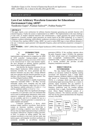
II.
DIRECT DIGITAL
SYNTHESIZER
The idea behind Direct Digital Synthesis
(DDS) is an electronic method for digitally creating
waveforms and frequencies from a single Direct
Digital Frequency Synthesis (DDFS or simply DDS),
also known as Numerically Controlled Oscillator
(NCO), is a technique which uses digital-data and
mixed/analog-signal processing blocks as a means to
generate signal waveforms that are repetitive in
nature. Direct Digital Synthesizer (DDS) is a type of
frequency synthesizer used for creating arbitrary
waveforms from a single, fixed-frequency reference
clock. Direct Digital Synthesizer consists of a
frequency reference. The reference provides a stable
time base for the system and determines the frequency
accuracy of the DDS.
Frequ
ency
Contr
oller
Numer
ical
Contro
ller
oscillat
or
Reference
Oscillator
jopopjijop
Digital
-ToAnalog
Conver
ter
Rec
ons
tru
cti Analog
O/P
on
Lo
w
pas
s
filt
er
951 | P a g e
2. Nandkishor Gupta et al Int. Journal of Engineering Research and Applications
ISSN : 2248-9622, Vol. 3, Issue 6, Nov-Dec 2013, pp.951-956
(“DDS BLOCK DIAGRAM”)
DDS technique consists in digital processing
to generate signals at different frequencies and
phases selectable by software, from a reference clock.
The number of bits of the DDS and the desired output
signal frequency is given by
Where (δt is the duration of a DDS time
step (1/4) and op is the phase angle changing in one
time interval ot. Considering that the tuning word (M)
is the amount by which the phase accumulator
increments on each DDS time step and that 2N is the
capacity of the phase accumulator, then op = M / 2 N
(with N equal to the number of bits of the phase
accumulator). Combining these results gives the
frequency of the output sine wave. is the clock
frequency, then the frequency of the output sine wave
is equal to:
Fout = M X Fclk
2N
Above equation is known as the DDFS
"tuning equation." The frequency resolution of the
system equals. In a practical DDFS system, all the bits
out of the phase accumulator are not passed on to the
LUT, but are truncated, leaving only the first 13 to 15
MSBs. A DDS has many advantages over its analog
counterpart, the phase-locked loop (PLL), including
much better frequency agility, improved phase noise,
and precise control of the output phase across
frequency switching transitions. The output frequency
of a DDS is determined by the value stored in the
frequency control register
DDS output frequency settling time is
determined mainly by the phase response of the
reconstruction filter. The superior close-in phase noise
performance of a DDS stems from the fact that it is a
feed-forward system. The DDS technique has higher
frequency resolution usually generators based on PLL
have a limited frequency resolution in the order of
1:106, total harmonic distortion (THD) of PLL
generators typically has values of -40 dB in
comparison with a THD better than -70 dB
achievable by DDS devices. The DDS devices are
software programmable and easy to use.
A.
Analog function generator / (ADC)
Analog signal generators based on a sine
wave oscillator were common before the inception of
digital electronics, and are still used. There was a
sharp distinction in purpose and design of radiofrequency and audio-frequency signal generator
A typical function generator usually
comprises of a triangular waveform whose frequency
can be controlled smoothly as well as in steps. This
triangular wave is used as the basis for all of its other
outputs. The triangular wave is generated by
www.ijera.com
www.ijera.com
repeatedly charging and discharging a capacitor from
a constant current source. This produces a linearly
ascending or descending voltage ramp. As the output
voltage reaches upper and lower limits, the charging
and discharging is reversed using a comparator,
producing the linear triangle wave. By varying the
current and the size of the capacitor, different
frequencies may be obtained.
Function generators, like most signal
generators, may also contain an attenuator, various
means of modulating the output waveform, and often
the ability to automatically and repetitively "sweep"
the frequency of the output waveform (by means of a
voltage-controlled oscillator) between two operatordetermined limits. This capability makes it very easy
to evaluate the frequency response of a given
electronic circuit.
More advanced function generators use Direct
Digital Synthesis (DDS) to generate waveforms.
Arbitrary waveform generators use DDS to generate
any waveform that can be described by a table of
amplitudes
B. Digital function generator / DAC
Digital Signal Generator is an easy-touse, virtual signal generator. It can produce white
noise signals, sine wave, square wave, trigon wave,
beat wave, sweep sine wave and a signal defined by a
windows WAV file.
The Digital Block is the heart of this digitally
controlled function generator. Symmetry and
frequency variation is direct result of the design of this
block. In this design the emphasis was on simplicity
and some target specifications at the top of the
frequency variation were compromised in order to
achieve greater simplicity.
This design achieves 28 frequencies in the
range of 100Hz to 100 kHz. Whilst the 17 frequencies
from the range 100Hz to 10 kHz are symmetry
variable in five steps from 0.1 to 0.5 the last eight
frequencies only managed to achieve symmetry
variations 0.5 and 0.25. This is due to some limiting
factors that will be discussed later. The table of
achievable frequencies can be found at the end of this
report. User inputs are also digitally processed in this
function generator and sent out as digital signals to
other parts of this function generator namely the
amplifier module. Also a filter selector circuit is built
in after the digital block. The user inputs controlling
frequency and symmetry are also built into this control
block.
Therefore it is clear that the digital block can
be divided into 4 distinct blocks, each with its own
functionality. These blocks are the control module,
counter module, filter control module and 8-bit D/A.
The D/A chosen is the DAC0801LCN. The
interconnections will be discussed later but the
thickness of the line indicates the number of bits in the
bus lines. As the name suggests the control module
takes user inputs, processes them and sends them out
952 | P a g e
3. Nandkishor Gupta et al Int. Journal of Engineering Research and Applications
ISSN : 2248-9622, Vol. 3, Issue 6, Nov-Dec 2013, pp.951-956
to the respective modules. The functionality module
generates the count, varying between 0 to 255 in 256
steps or in 64 steps. The 8-bit D/A changes this count
into a wave and the filter selector module selects
which filter in the filter block to pass the signal
through.
New high-speed DACs provide up to 16-bit
resolution at sample rates in excess of 1 GS/s. These
devices provide the foundation for an AWG with the
bandwidth and dynamic range to address modern radio
and communication applications. In combination with
a quadrature modulator and advanced digital signal
processing, high-speed DACs can be applied to create
a full-featured vector signal generator with very high
modulation bandwidth. Example applications include
commercial wireless standards such as Wi-Fi (IEEE
802.11), WiMAX (IEEE 802.16) and LTE, in addition
to military standards such as those specified in the
Joint Tactical Radio System (JTRS) initiative. Also,
broad modulation bandwidth allows multi-carrier
signal generation, necessary for testing receiver
adjacent channel rejection.
C. Arbitrary waveform generators, or AWGs
Arbitrary
waveform
generators
are
sophisticated signal generators which allow the user to
generate arbitrary waveforms, within published limits
of frequency range, accuracy, and output level. Unlike
function generators, which are limited to a simple set
of waveforms; an AWG allows the user to specify a
source waveform in a variety of different ways.
AWGs are generally more expensive than function
generators, and are often more highly limited in
available bandwidth; as a result, they are generally
limited to higher-end design and test applications.
III.
WHY ARM PROCESSOR USED
ARM used because this processor is risc
design & more regions.
ARM (Advanced Risc Machine) Microprocessor
was based on the Berkeley/Stanford Risc concept
ARM is programmable as little endian or big
endian data alignment in memory.
Originally called Acorn Risc Machine because
developed by Acorn Computer in 1985
Financial troubles initially plagued the Acorn
Company but the ARM was rejuvenated by
Apple, VLSI technology, and Nippon Investment
and Finance
Licenses ARM core designs to semiconductor
partners who fabricate and sell to their customers.
4 bit field can shift an 8 bit data field into any one
of 16 possible positions
If necessary to use a complete 32 bit word, then
break it up into four groups of 8 bits and use shift
and add instructions to reassemble
18 data processing instructions of type:
<Opcode> <dest reg.> <op1> <op2>
ADC Add with Carry; ADD Add; AND Bitwise
logical AND; BIC Bit Clear CMN Compare
www.ijera.com
www.ijera.com
Negated; CMP Compare; EOR Exclusive OR;
MOV Move; MVN Move Not; ORR Bitwise
logical OR; RSB Reverse Subtract; RSC Reverse
Subtract with Carry; SBC Subtract with Carry;
SUB Subtract; TEQ Test Equivalence; TST Test
and Mask
Shift instruction fields are 5 bits, so shifts can
accurately place in up to all 32 positions
Shift instructions: LSL logical shift left, ASL
Arithmetic shift left, LSR Logical shift right,
ASR Arithmetic shift right, ROR Rotate right,
RRX Rotate right with extend
Use of Software Interrupt instruction (SWI)
causes ARM to go into supervisor mode with
private
registers R13_svc and R14_svc as extras to allow
OS kernel to protect the stack and link registers
IV.
WHY DIRECT DIGITAL
SYNTHESIZER
Some advantages are as follows in support of
Direct Digital Synthesizer: The frequency is tunable with sub – Hertz
resolution.
The phase is digitally adjustable.
Conceptually simple design & low part counts
(these help keep cost down).
No drift due to temperature changes or aging of
components (as long as the clock is stable).
Addition of arbitrary waveform generation is not
conceptually difficult.
DDFS have capability that usually specified
as the maximum sine wave output frequency. the sine
waves can be generator at nearly half the clock
frequency. Generated a square wave from a sine wave
amplitude is less than 0. However, maintaining the
fidelity of a square wave is harder because of the rich
harmonic content – the post – processing circuitry
(e.g. amplitude adjustment) needs to be of a higher
bandwidth than for a single sine wave. Thus, it is not
uncommon to see the square wave maximum
frequency to be half or less of the sine wave maximum
frequency. A similar comment applies for pulse
generation, where the spectrum requirement can be
even more demanding.
Some synthesizer provides specialized
waveforms as added features. These are addition
functions f(ξ) that are stored in the generator read only
memory they can be useful for specialized task. Since
these specialized waveform need to be generator
accurately, their maximum output frequency will often
be much less than the typical sine & square wave
frequencies available from the generators.
953 | P a g e
4. Nandkishor Gupta et al Int. Journal of Engineering Research and Applications
ISSN : 2248-9622, Vol. 3, Issue 6, Nov-Dec 2013, pp.951-956
(“DDFS FUNCTION BLOCKS AND SIGNAL
FLOW DIAGRAMS”)
The main components of a DDFS are a phase
accumulator, phase-to-amplitude converter (a sine
look-up table), a Digital-to-Analog Converter and
filter. A DDFS produces a sine wave at a given
frequency. The frequency depends on three variables;
the reference-clock frequency fclk and the binary
number programmed into the phase register
(frequency control word, M), length of n-bit
accumulator. The binary number in the phase register
provides the main input to the phase accumulator.
V.
PROBLM STATEMENT
Different problem statement for the describe
the below in show.
A. Waves stability
The some problem function generator is
wave’s is not stable because resolutions change is
wave’s unstable and changes the amplitude so stability
is not proper.
B. Environment effected
When a temperature is change for the
environments so frequency phase & amplitude is
change because due to the variation or the output and
you have not aureate output waveform signal
www.ijera.com
fm). Components are separated from the original
frequency by a bandwidth of fs - 2fm. If f(t) is sampled
at a rate less than 2fm samples per second, the
undesirable components overlap the. Original
components in the frequency spectrum, and
consequently f(t) cannot be recovered from the
original sampled signal. This phenomenon is known
as aliasing. To reconstruct a function that has been
sampled at the rate fs > 2fm, the sampled signal must be
directed through a low-pass filter that has a cutoff
frequency of fm. The magnitude plot of the low-pass
filter response must have a slope that is sufficiently
steep in the cutoff region to reduce the magnitude of
the lowest undesirable frequency component fs - fm to
an acceptable level. Arbitrary function generator was
designed to interface with a PC. This specific
computer platform was chosen because it is very
common in both industrial and scientific environments
VII.
USER INTERFACE DESIGN
The arbitrary Waveform generated (AWG)
had two modes of operation: command mode &
Source mode. Source mode the AWG source the
selected waveform specify frequency after the user
start the waveform from the command mode. The
command mode (which the AWG starts in at reset) the
user navigates through a series of menus in order to
setup the desired waveforms for sourcing set the
frequency at which the AWG will source a waveform,
or can select to start a waveform. When the user
selects to change the frequency a prompt is shown at
which the user enters the frequency in decimal from 0
to 9999 Hz. The frequency is not associated with any
specific waveform. After the frequency is entered the
AWG returns to the main menu. When the user selects
to start the waveform she will be prompted for which
waveform to Start and then that waveform will be
initialized and source mode will be entered. The
waveform may be stopped by pushing enter ('D') on
the keypad returning the AWG to the main menu and
the command mode.
VIII.
C. The phase is adjustable
Some function generator use phase and
amplitude adjustable used ring (nop) and that ring
(nop) some time is automatic move and phase &
amplitude is automatic change
VI.
METHODOLOGY
The design of this waveform generator
utilizes the theory of sampled-data systems. Sampling
theorem states that a time-dependent function f (t) that
is limited in bandwidth to fm and sampled at a rate fs >
2fm can be completely reconstructed from its samples.
The waveform is a discrete time signal that processed
all of the frequency components in the interval 0 < f <
fm . Additional frequency components that are imposed
by the sampling process appear in the interval f > (fs –
www.ijera.com
THE OPERATION STAGE OF
SYSTEM
The whole operation of the system can be
listed as in the following steps:
Training the ARM to obtain one and synapse
weights which are appropriate to approximate the
desired function.
Applying pervious stage results to control unit of
system that stores results in an internal memory
assigned to this goal.
Calculating desired frequency of wave and
applying related number to the phase
accumulator’s input.
After initializing the system by related
numbers, it goes to normal operation mode and
generates the trained waveform by the specified
frequency
954 | P a g e
5. Nandkishor Gupta et al Int. Journal of Engineering Research and Applications
ISSN : 2248-9622, Vol. 3, Issue 6, Nov-Dec 2013, pp.951-956
IX.
SYSTEM ANALYSIS
This system can be analysis waveform. This
can be different type wave generated and check the
phase amplitude & wave type this system used ARM7 processor this processor is advance risc machine
because this is reduced instruction set computer this is
one pin 2 to 3 instruction and this is completed only
one cycle for one instruction do not used more time.
This is a high speed performance so this is used for the
system. System is a stable, amplitude variation
decreases, and high speed performance.AWG
(Arbitrary Waveform Generator) this type waveform
generated is easily can used look up table this table
help for different type waveform generated because
different type wave design for this system and easily
to perform low coast and use for education lab. This is
the computer interfacing and the this interfacing used
you have online operate power plant, Pharmacy
Company, any area for human is do not go that area so
this generator used and operated for and give
instruction. This can used hart bit sensor and see the
hart bit wave oscilloscope. This system generated for
saw tooth wave, triangular wave, squarwave and
rectangular wave.
X.
THE SYSTEM IMPROVMENT
The design of this project used for ARM-7.
ARM-7 is the advance Risc machine and this
processor take one cycle is completed instruction. The
design of the AWG was limited partly by time which
necessitated the use of code from previous labs which
limited the way some of the parts of the AWG were
implemented. The timer1 interrupt routine could be
trimmed down quite a bit to provide less limitation on
the maximum sample frequency. The minimum
sample frequency could also be decreased by using a
status register to count timer1 interrupts allowing
samples to wait more than 65536 ticks before
outputting. The user input system is also less than
ideal. The menus could be implemented more cleanly
so that there is a generic menu data type which can be
loaded from Flash to specify each menu's contents
while a state variable is used to indicate which menu
the user is currently in. As it stands the AWG does not
need this versatile menu system, but any additional
menus would make the system easier to implement
and control.
XI.
www.ijera.com
Analysis for the (DDS) direct digital synthesizer. This
system generated for saw tooth wave, triangular wave,
squarwave and rectangular wave
(“DIFFERENT TYPE WAVE’S”)
An arbitrary waveform generator (AWG) is
an advanced signal generator that can generate a
waveform of almost any shape. The generated
waveform can then be inserted into the device you
wish to test and then anal ysed as it progresses through
the device to confirm correct operation, or to highlight
a fault. Arbitrary waveform generators are often
expensive and so are usually only found in high–end
test equipment, however, several Pico Scope PC
Oscilloscopes include a built–in AWG
(“ARBITRARY WAVEFORM”)
REFERENCE
[1]
[2]
CONCLUSION
This paper describes the design and operation
of Low-Cost (AWG) Arbitrary Waveform Generator
for Educational Environment using ARM-7 suitable
for use in undergraduate laboratories as an analytical
tool or as a student design project. Using custom
software and a personal computer, this system can
generate any function of time that can be represented.
Describe of the analog & Digital function generator
and whose is batter decided. This is used (DDS) direct
digital synthesizer this explain the use ARM7
Processor this processor benefit for used this project.
www.ijera.com
[3]
[4]
[5]
Amauri A Assef1 Joaquim M Maia1, Fábio
K Schneide (2013) A reconfigurable arbitrary
waveform generator using PWM modulation
for ultrasound research
Mr. Mani Dargahi Fadaei,(2013) A Low-Cost
Programmable Arbitrary Function Generator
for Educational Environment
Walter F. Adad, Ricardo J. Iuzzolino (2012,)
Low distortion signal generator based on
direct
digital
Synthesis
for
ADC
characterization
Khosro Rajabpour Moghaddam(2011) New
Arbitrary Function Generator Based On
Artificial Neural Network
IEEE, Tech. Rep., “IEEE Std 1241.2001,
IEEE Standard for Terminology and Test
955 | P a g e
6. Nandkishor Gupta et al Int. Journal of Engineering Research and Applications
ISSN : 2248-9622, Vol. 3, Issue 6, Nov-Dec 2013, pp.951-956
[6]
[7]
www.ijera.com
Methods for Analog-to-Digital Converters,”
2001
J.Vankka and K.Halonen, Direct Digital
Synthesizers:
Theory,
Design
and
Applications. Norwell, MA: Kluwer, 2001.
Rahrooh, A., and T. T. Hartley, “Adaptive
Matrix Integration for Real-Time Simulation
of Stiff Systems,” IEEE Transaction on
Industrial Electronics, 36, no.1 (February
1989)
www.ijera.com
956 | P a g e