Converged Office Engineering Session
•
2 likes•531 views

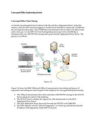
1. When an OCS client logs in, the CS1000 is informed so it can route calls to that user. 2. An INVITE message is sent from the OCS client to the FE Server, then to the Application Proxy and NRS to route to the correct Signalling Server. 3. The Signalling Server processes the request and acquires the phone, responding with a 200 OK message back through the chain to the OCS client.

Recommended
Recommended
More Related Content
What's hot
What's hot (15)
Viewers also liked
Similar to Converged Office Engineering Session
Similar to Converged Office Engineering Session (20)
Recently uploaded
Recently uploaded (20)
Converged Office Engineering Session
- 1. Converged Office Engineering Session Converged Office Client Startup As initially demonstrated in the live demo in the lab with the configuration below, in the first instance, when the OCS client has logged in, the OCS Front End Server informs the CS1000 that the user login has taken place. The CS1000 has to be informed of this in order to be able to route calls to this user. It is the SIP CTI Front End Signalling Server part of the CS1000 that is informed of this via a SIP INVITE message that comes from the Application Proxy Server. The process is as follows: NRS/SPS Active Directory Call Server 3 OCS2007 4 FE Server 2 6 5 7 7 1 SIP CTI Front End 7 Signalling Server MCM/Application Proxy Figure 5.4 Figure 5.4 shows the MOC (Microsoft Office Communicator) client startup and process of registration and subsequent control request of the telephone for converged desktop functionality. 1. The Office Communicator client starts and sends a SIP INVITE message to the OCS FE Server asking for control of the telephone. 2. The OCS FE Server validates the request (via AD) and forwards it to the OCS Application Proxy Server. 3. The OCS Application Proxy Server the forwards the INVITE to the NRS/SPS 4. The NRS responds with the “Moved Temporarily” as it looks up, and then provides the IP address of the appropriate Node (SIP CTI Server)
- 2. 5. The OCS Application Proxy Server can now send the INVITE to the Signalling Server Node IP 6. The Signalling Server then processes the request with the Call Server for the phone DN acquisition. 7. The Signalling Server sends back a “200 OK” message to the OCS Application Server, forwards back to the OCS FE Server and then to the OCS Client PC. The phone is now controlled. Traffic monitoring of this telephone control request process was initiated on initial login, and here we see the client startup and registration process in more detail. Instance-Id: 00000 A66 Client PC IP address Direction: incoming Peer: 47.164.154.177:1219 User SIP URI Message-Type: request Start-Line : INVITE sip:4115@demolab .com SIP/2.0 From: <sip:usera@demolab.com>;tag=b0434 a26b8;epid =f60275d516 To: <sip:4115@demolab.com> CSeq: 1 INVITE … Message-Body : <?xml version="1.0"?> <RequestSystemStatus xmlns ="http://www.ecma-international .org/standards /ecma- 323/csta/ed3"><extensions ><privateData><private><lcs:line xmlns:lcs="http://schemas.microsoft.com/Lcs/2005/04/RCCExtension ">tel:+33164554115 ; ext=4115</lcs:line></ Figure 5.5 1. SIP INVITE From The Client PC As indicated in Figure 5.5, a trace on the client PC, shows that RCC mode has only one INVITE message when starting the Office Communicator. Each call is associated to INFO messages and not INVITE messages. In this case, there will only be one session during the OC call duration. Additionally, the OC sends polling (INVITE) messages every 10 minutes to ensure the telephone is still controlled.
- 3. Instance-Id: 00000 A6E Direction: outgoing Application Proxy Server Peer: 47.164.113.136:5060 Message-Type: request Start-Line : INVITE sip:4115@demolab .com SIP/2.0 From: “User A"<sip:usera@demolab .com>;tag=b0434a26b8;epid=f60275 d516 To: <sip:4115 @demolab .com> CSeq: 1 INVITE Call-ID: b094883980 e94e0490ed9174a99f481d ms-user-data: ms-publiccloud =true;ms-federation =true Record-Route: <sip:DemoOcsFeSrv1.demolab .com;transport=tcp;ms-role-rsto; lr>;tag=B62E609FD01E60435 DE8508 CC53B6483 Via: SIP/2.0/TCP 47.164.113.137:2608;branch=z9hG4bK932C8642.99918 F3C;branched =FALSE Max-Forwards: 69 Figure 5.6 2. Front End Server forwards the INVITE to the Application Proxy Server Message monitoring on the FE server on Figure 5.6 shows that the INVITE is then forwarded onto the Application Proxy Server. It is important to note here that the routing entry for the Proxy Server has to be defined in the FE Server. Instance-Id: 000000 FE Direction: outgoing Peer: 47.164.113.108:5060 NRS IP Address Message-Type: request Start-Line : INVITE sip:4115@demolab .com:5060;maddr =47.164.113.108;transport=tcp;x-nt-netfeature = x-nt-redirect SIP/2.0 From: “User A"<sip:usera@demolab .com>;tag=b0434a26b8;epid=f60275 d516 To: <sip:4115 @demolab .com> CSeq: 1 INVITE Figure 5.7 3. Application Proxy Forwards to the NRS As shown in figure 5.7, the INVITE is then forwarded on to the NRS for correct routing within the telephony network. The NRS IP address is derived from the configuration parameter in the MCM.
- 4. Instance-Id: 000000 FF Direction: incoming A Peer: 47.164.113.108:5060 Message-Type: response Start-Line : SIP/2.0 302 Moved Temporarily From: “User A"<sip:usera@demolab .com>;tag=b0434a26b8;epid=f60275 d516 To: <sip:4115@demolab .com>;tag=16951 CSeq: 1 INVITE B … Contact: <sip:4115;phonecontext = cdp.udp@ctflab.net:5060 ;maddr=47.164.113.106;transport =tcp;xnt- net-feature =x-nt-redirect;x-nt-redirect=redirect-server> Content-Length : 0 Message-Body: – $$end_record Figure 5.8 4. NRS directs to the appropriate SIP CTI Server Monitoring on the Application Proxy Server as depicted in Figure 5.8 shows that the NRS processes the INVITE message and sends it back to the Proxy Server with the appropriate Node IP address (SIP CTI Server) responsible for handling the DN range (41xx) (A). The Proxy Server then needs to contact this SIP CTI Server and re-issue the same INVITE back to this server. Instance-Id: 00000101 Direction: outgoing Peer: 47.164.113.106:5060 Node IP address of SIP CTI Message-Type: request Front End Signalling Server Start-Line: INVITE sip :4115;phone- context=cdp.udp@demolab .comt:5060;maddr=47.164.113.106;transport=tcp;x-ntnet- feature=x-nt-redirect;x-nt-redirect=redirect-server SIP /2.0 From: “User A"<sip:usera@demolab .com>;tag=b0434a26b8;epid=f60275d516 To: <sip:4115@demolab.com> CSeq: 1 INVITE 1 Call-ID: b094883980 e94e0490ed9174a99f481d 2 Record-Route: <sip:DemolabOcsProxySrv .demolab .com;transport=tcp;lr>;tag=8C65C54CB3D548F691E917450 BD A37AF Via: SIP/2.0/TCP 47.164.113.136:1613;branch=z9hG4bK3560E034.F1D7AAD1;branched =TRUE Max-Forwards : 68 Content-Length: 321 Via: SIP/2.0/TCP 47.164.113.137:2608;branch=z9hG4bK932C8642.99918F3C;branched=FALSE;ms- receivedport= 2608;ms-received-cid=700 Via: SIP/2.0/TCP 47.164.154.177:1219;ms-received-port=1219;ms-received -cid=4C00 ms-user-data: ms-publiccloud =true;ms-federation=true 3 Record-Route: <sip:DemolabOcsFeSrv 1.demolab .com;transport=tcp;ms-role-rsto; lr>;tag=B62E609FD01E60435DE8508CC53B6483 Contact: <sip:usera@demolab.com;opaque=user:epid:kI5Vslm4gl2F2-3nWKKnhQAA ;gruu> User-Agent: UCCP/2.0.6362.36 OC/2.0.6362.36 (Microsoft Office Communicator ) Content-Disposition : signal;handling=required
- 5. Figure 5.9 5. Application Proxy Server sends the INVITE back to the appropriate SIP CTI Server The trace on Figure 5.9 shows points of note: 1. The Signalling Server constructs an EPID (Endpoint Identifier) to store information related to the DN (Dialled Number). It associates the SIP URI of the user with this epid. 2. The Signalling Server now is aware of the Recorded Route of the Application Proxy Server in the OCS environment. 3. The Signalling Server also is now aware of Recorded Route of the OCS Front End Server This information will be necessary to build the SIP INFO message related to an RCC call for this DN. (In this case 4115). Also, the SIP INFO will contain everything required in order for it to route the the correct user client PC and therefore the MCM will not have to perform the Caller DN number lookup operation. A ELAN32 I MTYP=3B IACR TN=0 TIME=12:35:08 ELAN32 IN 53C56D7F OUT 53C56D80 QSIZE 00000000 ELAN32 03 20 00 00 00 00 1 E 3B 00 A6 00 00 95 01 05 36 02 41 15 E6 ELAN32 0C BF EE 01 FF FF FF 00 00 0 F FF 00 00 ELAN32 O MTYP=3C IACS TN=0 TIME=12:35:08 ELAN32 IN 53C56D81 OUT 00000000 QSIZE 00000000 ELAN32 03 27 00 00 00 00 1 E 3C 00 A6 00 00 95 01 05 36 02 41 15 E6 ELAN32 0C BF EE 01 FF FF FF 00 00 0 F FF 00 00 37 02 61 00 AA 01 00 B Figure 5.10 6. The Signalling Server processes the INVITE message Figure 5.10 indicates via internal CS1000 switch messaging the processed INVITE data being passed to the Call Server. There are some points worth noting: A. the DN number (in this case 4115) has to match the number that is configured for the user in Active Directory. B. When the IACS (Infosec Assurance and Certification Services) contains the Status Info Element “AA 01 00” string this is the indication that the Signalling Server successfully acquired the telephone set associated with DN 4115. Any other string means that the acquisition was not successful.
- 6. Instance-Id: 00000104 CS1000 Node IP address Direction: incoming Peer: 47.164.113.106:5060 Message-Type: response Start-Line : SIP/2.0 200 OK From: “User A"<sip:usera@demolab .com>;tag=b0434a26b8;epid=f60275 d516 To: <sip:4115 @ctflab.net>;tag=19042 ee0-6a71a42f-13c4-40030 -1f8cde-706ef19f-1f8cde CSeq: 1 INVITE Figure 5.11 7. The Signalling Server Responds to the INVITE When the “200 OK” message is received from the Signalling Server, the Application Proxy Server sends it to the FE Server, which then forwards it on to the Client PC running the Office Communicator. So this exercise indicates how the CS1000 and OCS environments have integrated and initially communicated by informing each other of users details, and mapping SIP URI’s to DN’s for cohesive communication. Converged Office call scenario in Remote Call Control Next, as demonstrated in the lab in the second instance, with the configuration detailed below, a user logged in as RCC mode, has access to a fully integrated scenario in which the client has control of the phone. Here we explore how in an RCC call, (a), this initial information would be used in facilitating this transaction. Figure 5.12 shows the flow of an incoming RCC call.
- 7. Active Directory SIP CTI Front End Signalling Server 1 3 OCS2007 4 FE Server 2 5 MCM Proxy 3.0 RCC User Phone OCS Client A (4116) Figure 5.12 Calling number is 4116 Called number is 4115 The message flow is as follows: 1. The call is presented to the controlled telephone. The Call Server then sends this message (via the CS1000 internal mechanism) to the Signalling Server indicating that the call is presented to the controlled telephone. 2. The SIP CTI Front End Singalling Server then initiates the SI INFO (not INVITE) to the OCS Application Proxy Server (on which the MCM resides) 3. The MCM then tries to lookup the Calling number. 4. The OCS Application Proxy Sever then forwards this INFO message to the OCS Front End Server 5. The OCE FE Server then sends this INFO message to the client PC running the OCS client. On the previous live demo in the lab, internal message monitoring and SIP messaging on the various elements of the Converged Office Solution, Call Server, SIP Proxy Server, OCS Application Proxy was enabled on initiation of this RCC call, and the breakdown of this messaging structure is analysed from Figure 5.13.
- 8. ELAN32 O MTYP=1A USM TN=096 0 00 16 TIME=13:04:25 A ELAN32 IN 53FAFF29 OUT 00000000 QSIZE 00000000 Internal messaging from the Call Server to Singalling Server indicating call is presented ELAN32 03 33 00 00 61 00 16 1 A 00 00 00 00 37 02 61 00 36 02 41 15 to the controlled telephone ELAN32 3B 01 08 38 01 03 3A 02 61 01 39 02 41 16 3C 01 08 96 04 00 ELAN32 00 0B A5 5F 07 0B 01 14 08 0D 04 19 The Signalling Server then generates the INFO sip:userA@demolab.com;opaque=user:epid:kI5Vslm4gl2F2-3nWKKnhQAA;gruu SIP/2.0 SIP INFO message and Corresponding From: <sip:4115@demolab.com>;tag=19042ee0-6a71a42f-13c4-40030-1f8cde-706ef19f-1f8cde Application Proxy sends it to the OCS Server (MCM) B To: “User A"<sip:usera@demolab.com>;tag=b0434a26b8;epid=f60275d516 Call-ID: b094883980 e94e0490ed9174a99f481d CSeq: 29 INFO Via: SIP/2.0/UDP 47.164.113.106:5060;branch=z9hG4bK-1f93be-7b591ea8-55d0a836 Content-Disposition: signal;handling=required Max-Forwards: 70 The OCS Application Proxy Server and Front Supported: 100rel,x-nortel-sipvc,replaces,timer End Server route details are derived from User-Agent: Nortel CS1000 SIP GW release_5.0 version_sse-5.00.31 The EPID (end point ID ) Route: <sip:DemoLabOcsProxySrv .demolab.com;transport=tcp;lr>;tag=8C65C54CB3D548F691E917450BDA37AF Route: <sip:DemoLabOcsFeSrv1.demolab.com;transport=tcp;lr;ms-role-rs- to>;tag=B62E609FD01E60435DE8508CC53B6483 Contact: <sip:4115;phone -context=cdp.udp@ctflab.net:5060;maddr=47.164.113.106;transport=tcp;x-nt-net-feature=x-nt- redirect;x-ntredirect= redirect-server> Content-Type: application/csta+xml Figure 5.13 1. Incoming Call presented to the controlled telephone A. Shows internal messaging in the CS1000. The dialed digits (4115) are passed from the Call Server to the SIP CTI Front End Signalling Server. B. SIP tracing on the Signalling Server out to the Application Proxy server indicates how the stored information from the previous handshaking communication between the two systems is now utilized. ProcessRequestFromGateway Request = INFO XmlModificator .Apply: invoked for DeliveredEvent LookupUserData: search for msRTCSIPLine = tel:*;ext = 4116 LookupUserName: trying to find in AD cache AD Cache: getValues : indexName : "msRTCSIPLine= tel:*;ext" indexValue : "4116" Debug: ProcessRequestFromGateway : TR87 SIP: Sent by MCM: Figure 5.14 2. The INFO message is received by the OCS Application Proxy Server (SIP message sent by MCM) As seen in Figure 5.14 In RCC mode, the INFO messages already contain the required information to e able to route the user DN and the SIO URL. The Siganlling Server stores
- 9. this information inside the EPID when the telephone is acquired. MCM does not have to lookup the called number to SIP URI for an RCC call. However, it can perform a lookup to the calling number. Request: INFO sip:usera@demolab.com;opaque=user:epid:kI5Vslm4gl2F2-3nWKKnhQAA;gruu via: SIP/2.0/TCP 47.164.113.106:5060;branch=z9hG4bK-1f93be-7b591ea8-55d0a836; ms-received-port=3597;ms-receivedcid=1000 from: <sip:4115@demolab.com>;tag=19042ee0-6a71a42f-13c4-40030-1f8cde-706ef19f-1f8cde to: “UserA"<sip:usera@demolab.com>;tag=b0434a26b8;epid=f60275d516 Info message received from call-id: b094883980e94e0490ed9174a99f481d Signalling Server cseq: 29 INFO ?xml version="1.0" encoding="UTF-8"?><DeliveredEvent xmlns="http://www.ecma-international.org/standards/ecma- 323/csta/ed3"><monitorCrossRefID>166</monitorCrossRefID><connection><callID>2981</callID> <deviceID>tel:+33164554115 ;ext=4115</deviceID></connection><alertingDevice><deviceIdentifier>tel:+33164554115 ;ext=4115</ deviceIdentifier></alertingDevice> <callingDevice><deviceIdentifier>tel:4116;phonecontext=cdp.udp</deviceIdentifier></callingDevice><calledDevice> <deviceIdentifier>tel:+33164554115 ;ext=4115</deviceIdentifier></calledDevice><lastRedirectionDevice><notRequired/></lastRedir ectionDevice><localConnectionInfo>alerting</localConnectionInfo><cause>normal</cause></DeliveredEvent> 1/11/2008 3:57:03 PM: 3.0.1.77: Debug: ProcessRequestFromGateway Request = INFO 1/11/2008 3:57:03 PM: 3.0.1.77: Debug: XmlModificator.Apply: invoked for DeliveredEvent 1/11/2008 3:57:03 PM: 3.0.1.77: Debug: LookupUserData: search for msRTCSIPLine= tel:*;ext = 4116 AD Lookup 1/11/2008 3:57:03 PM: 3.0.1.77: Debug: LookupUserName: trying to find in AD cache 1/11/2008 3:57:03 PM: 3.0.1.77: Debug: AD Cache: getValues: indexName: "msRTCSIPLine= tel:*;ext" indexValue: "4116“ Request: INFO sip:usera@demolab.com;opaque=user:epid:kI5Vslm4gl2F2-3nWKKnhQAA;gruu via: SIP/2.0/TCP 47.164.113.106:5060;branch=z9hG4bK-1f93be-7b591ea8-55d0a836;ms-received-port=3597;ms-received- cid=1000 from: <sip:4115@demolab.com>;tag=19042ee0-6a71a42f-13c4-40030-1f8cde-706ef19f-1f8cde to: “User A"<sip:usera@demolab.com>;tag=b0434a26b8;epid=f60275d516 call-id: b094883980e94e0490ed9174a99f481d Info message sent to FE Server cseq: 29 INFO ?xml version="1.0" encoding="UTF-8"?><DeliveredEvent xmlns="http://www.ecma-international.org/standards/ecma- 323/csta/ed3"><monitorCrossRefID>166</monitorCrossRefID><connection><callID>2981</ callID><deviceID>tel:+33164554115 ;ext=4115</ deviceID></connection><alertingDevice><deviceIdentifier>tel:+33164554115 ;ext=4115</deviceIdentifier></ alertingDevice><callingDevice>< deviceIdentifier>tel:+33169554116 ;ext=4116</deviceIdentifier></ A callingDevice><calledDevice><deviceIdentifier>tel:+33164554115 ;ext =4115</deviceIdentifier></calledDevice><lastRedirectionDevice><notRequired /></lastRedirectionDevice><localConnectionInfo>alerting</localConnectionInfo><cause>normal</cause></DeliveredEvent> Figure 5.15 3. MCM Looks up the calling DN number. Here, as depicted in figure 5.15, the MCM tries to perform the lookup for the calling number. The Signalling Server already has the E.164 telephone format for the Called Number. It is part of the EPID generated during the telephone acquisition process by the
- 10. OCS client. There is no impact on the message routing even if there is no match for the Calling Number. The purpose is only to replace the calling number with the E.164 format number. (A) Instance-Id: 000001C2 Direction: outgoing Peer: 47.164.113.137:5060 OCS FE IP address Message-Type: request Start-Line: INFO sip:usera@demolab.com;opaque=user:epid:kI5Vslm4gl2F2-3nWKKnhQAA;gruu SIP/2.0 From: <sip:4115@demolab.com>;tag=19042ee0-6a71a42f-13c4-40030-1f8cde-706ef19f-1f8cde To: “User A"<sip:usera@demolab.com>;tag=b0434a26b8;epid=f60275d516 CSeq: 29 INFO Call-ID: b094883980e94e0490ed9174a99f481d Via: SIP/2.0/TCP 47.164.113.136:2013;branch=z9hG4bKE43CDFCD.E8DF3A61;branched=TRUE Figure 5.16 4. The OCS Application Proxy Server forwards the INFO message to the OCS Front End Server Instance-Id: 00000B46 OC client PC IP address Direction: outgoing Peer: 47.164.154.177:1219 Message-Type: request Start-Line: INFO sip:47.164.154.177:1219;transport=tcp;ms-opaque=eb89915611;ms-received-cid=4C00;grid SIP/2.0 From: <sip:4115@demolab.com>;tag=19042ee0-6a71a42f-13c4-40030-1f8cde-706ef19f-1f8cde To: “User A"<usera@demolab.com>;tag=b0434a26b8;epid=f60275d516 CSeq: 29 INFO Call-ID: b094883980e94e0490ed9174a99f481d Via: SIP/2.0/TCP 47.164.113.137;branch=z9hG4bKD325EF8D.891B80DD;branched=FALSE;ms- internalinfo="abZRshPHdmZ78n8AVeVQlVIBFAXimJG4DdfUZOigAA" Authentication-Info: Kerberos rspauth="602306092A864886F71201020201011100 FFFFFFFF894FCA2C25064B8E6455B9E01309F83A", srand="41489DF8", snum="77", opaque="76A291EA", qop="auth", targetname="sip/CtfOcsFeSrv1.ctflab.net", realm="SIP Communications Service"Max-Forwards: 68 Via: SIP/2.0/TCP 47.164.113.136:2013;branch=z9hG4bKE43CDFCD.E8DF3A61;branched=TRUE;ms-received- port=2013;msreceived-cid=5000 Content-Length: 688 Via: SIP/2.0/TCP 47.164.113.106:5060;branch=z9hG4bK-1f93be-7b591ea8-55d0a836;ms-received-port=3597;ms-receivedcid Figure 5.17 5. The OCS Front End Server sends the INFO to the Office Communicator user Client PC This per-hop basis call walkthrough shows how the various messaging is interpreted amongst the servers and signaling systems that make up this solution, to enable a converged office call to be made successfully in fully converged environment.
- 11. As we also demonstrated in the live demo, three basic call features - Call Transfer, Call on Hold and Call Forward were also tested on the client. This was to determine if the expected behavior associated the telephony system would also be mirrored on the OCS client. There a number of configuration parameters required for this integrated environment to work in an intuitive fashion – and therefore be user friendly. PBX Integration has to be marked in Active Directory, in addition to the Server URI line being filled in with the appropriate user details e.g (userA@testdemo.com) as well as the user having activated Phone Integration on their Office Communicator client. Also, the Address Book Service in the Windows environment has to be set up correctly for each Office Communicator client. This results in the user receiving one, incoming merged pop-up toast on the PC, with the correct CLID (Calling Line Identification Display) details presented of the incoming call. The omission or incorrect input of any of these values will result in either a dual pop-up being presented (one for each device – with no indication of which pertains to what device) as well as the incorrect, or no CLID at all, being shown In this scenario, there will be two possibilities for an incoming call depending on the Preferred Calling Device value chosen by the user: If the user has selected, and then also set their Preferred Calling Device to be Computer, one incoming call notification pop-up is received, with an option to Redirect to phone as the answering device. If the user has selected, and then also set their Preferred Calling Device to be Phone, again, one incoming call notification pop-up is received, with an option to Redirect to communicator as the answering device Figure 5.4
- 12. As illustrated by the screenshots in Figure 5.4, both types of user defined settings, whether set to accept calls on the phone or the OCS client, both only receive one incoming call pop-up notification with the correct CLID indicated, as well as being offered the option of redirecting the call to the other device (or alternative devices – such as the mobile phone) if required. This is true of all the call scenarios attempted, as described earlier. The call features of Call Transfer, Call on Hold and Call Forward previously mentioned also worked as expected, even though there was no provision for these features on the PBX, they were purely set from the PC based, and user controlled client. A call initiated from any device, whether an internal user on a deskphone or an OCS client, or an externally generated call from a mobile phone or landline, all had the same result in that the user of the Nortel Converged Office Solution received uniform notifications according to what they had individually configured as their preferred communications device.