1. Configuring Frame Relay IV-153
FINAL DRAFT CISCO CONFIDENTIAL
Configuring Frame Relay
This chapter describes the tasks for configuring Frame Relay on a router or access server. For a
complete description of the commands mentioned in this chapter, refer to the “Frame Relay
Commands” chapter in the Wide-Area Networking Command Reference.
Although Frame Relay access was originally restricted to leased lines, dial-up access is now
supported. For more information, see the “Configure DDR over Frame Relay” section in the
“Configuring DDR” chapter of this manual.
To install software on a new router or access server by downloading software from a central server
over an interface that supports Frame Relay, see the “Loading System Images, Microcode Images,
and Configuration Files” chapter in the Configuration Fundamentals Configuration Guide.
To configure access between SNA devices over a Frame Relay network, see the “Configuring SNA
Frame Relay Access Support” chapter in the Bridging and IBM Networking Configuration Guide.
Frame Relay Hardware Configurations
One of the following hardware configurations is possible for Frame Relay connections:
• Routers and access servers can connect directly to the Frame Relay switch.
• Routers and access servers can connect directly to a channel service unit/digital service unit
(CSU/DSU), which then connects to a remote Frame Relay switch.
Note A Frame Relay network is not required to support only routers that are connected directly or
only routers connected via CSU/DSUs. Within a network, some routers can connect to a Frame
Relay switch through a direct connection and others through connections via CSU/DSUs. However,
a single router interface configured for Frame Relay can be only one or the other.
The CSU/DSU converts V.35 or RS-449 signals to the properly coded T1 transmission signal for
successful reception by the Frame Relay network. Figure 28 illustrates the connections between the
different components.
2. IV-154 Wide-Area Networking Configuration Guide
Frame Relay Configuration Task List
FINAL DRAFT CISCO CONFIDENTIAL
Figure 28 Typical Frame Relay Configuration
The Frame Relay interface actually consists of one physical connection between the network server
and the switch that provides the service. This single physical connection provides direct connectivity
to each device on a network, such as a StrataCom FastPacket wide-area network (WAN).
Frame Relay Configuration Task List
There are required, basic steps you must follow to enable Frame Relay for your network. In addition,
you can customize Frame Relay for your particular network needs and monitor Frame Relay
connections. The following sections outline these tasks. The tasks in the first two sections are
required.
• Enable Frame Relay Encapsulation on an Interface
• Configure Dynamic or Static Address Mapping
• Configure the LMI
• Configure Frame Relay Switched Virtual Circuits
• Configure Frame Relay Traffic Shaping
• Customize Frame Relay for Your Network
• Monitor the Frame Relay Connections
See the “Frame Relay Configuration Examples” section at the end of this chapter for ideas of how
to configure Frame Relay on your network. See the “Frame Relay Commands” chapter in the
Wide-Area Networking Command Reference for information about the commands listed in the tasks.
Enable Frame Relay Encapsulation on an Interface
To set Frame Relay encapsulation at the interface level, perform the following tasks beginning in
global configuration mode:
1. This command is documented in the “Interface Commands” chapter in the Configuration Fundamentals Command
Reference.
Task Command
Specify the serial interface, and enter interface
configuration mode.
interface serial number1
Enable Frame Relay, and specify the encapsulation
method.
encapsulation frame-relay [ietf]
Router DSU/CSU
V.35
S2304
Public Frame
Relay network
4-wire T1
Router
V.35
3. Configure Dynamic or Static Address Mapping
Configuring Frame Relay IV-155
FINAL DRAFT CISCO CONFIDENTIAL
Frame Relay supports encapsulation of all supported protocols in conformance with RFC 1490,
allowing interoperability between multiple vendors. Use the Internet Engineering Task Force (IETF)
form of Frame Relay encapsulation if your router or access server is connected to another vendor’s
equipment across a Frame Relay network. IETF encapsulation is supported either at the interface
level or on a per-virtual circuit basis.
For an example of how to enable Frame Relay and set the encapsulation method, see the sections
“IETF Encapsulation Examples” and “Static Address Mapping Examples” later in this chapter.
Configure Dynamic or Static Address Mapping
Dynamic address mapping uses Frame Relay Inverse ARP to request the next hop protocol address
for a specific connection, given its known DLCI. Responses to Inverse ARP requests are entered in
an address-to-DLCI mapping table on the router or access server; the table is then used to supply the
next hop protocol address or the DLCI for outgoing traffic.
Inverse ARP is enabled by default for all protocols it supports, but can be disabled for specific
protocol-DLCI pairs. As a result, you can use dynamic mapping for some protocols and static
mapping for other protocols on the same DLCI. You can explicitly disable Inverse ARP for a
protocol-DLCI pair if you know that the protocol is not supported on the other end of the connection.
See the “Disable or Reenable Frame Relay Inverse ARP” section later in this chapter for more
information.
Configure Dynamic Mapping
Inverse ARP is enabled by default for all protocols enabled on the physical interface. Packets are not
sent out for protocols that are not enabled on the interface.
Because Inverse ARP is enabled by default, no additional command is required to configure dynamic
mapping on an interface.
Configure Static Mapping
A static map links a specified next hop protocol address to a specified DLCI. Static mapping removes
the need for Inverse ARP requests; when you supply a static map, Inverse ARP is automatically
disabled for the specified protocol on the specified DLCI.
You must use static mapping if the router at the other end either does not support Inverse ARP at all
or does not support Inverse ARP for a specific protocol that you want to use over Frame Relay.
To establish static mapping according to your network needs, perform one of the following tasks in
interface configuration mode:
Task Command
Define the mapping between a next hop
protocol address and the DLCI used to
connect to the address.
frame-relay map protocol protocol-address dlci [broadcast]
[ietf] [cisco]
Define a DLCI used to send
International Organization for
Standardization (ISO) Connectionless
Network Service (CLNS) frames.
frame-relay map clns dlci [broadcast]
Define a DLCI used to connect to a
bridge.
frame-relay map bridge dlci [broadcast] [ietf]
4. IV-156 Wide-Area Networking Configuration Guide
Configure the LMI
FINAL DRAFT CISCO CONFIDENTIAL
The supported protocols and the corresponding keywords to enable them are as follows:
• IP—ip
• DECnet—decnet
• AppleTalk—appletalk
• XNS—xns
• Novell IPX—ipx
• VINES—vines
• ISO CLNS—clns
You can greatly simplify the configuration for the Open Shortest Path First (OSPF) protocol by
adding the optional broadcast keyword when doing this task. See the frame-relay map command
description in the Wide-Area Networking Command Reference and the examples at the end of this
chapter for more information about using the broadcast keyword.
For examples of how to establish static address mapping, see the “Static Address Mapping
Examples” section later in this chapter.
Configure the LMI
Beginning with Cisco IOS Release 11.2, the software supports Local Management Interface (LMI)
autosense, which enables the interface to determine the LMI type supported by the switch. Support
for LMI autosense means that you are no longer required to configure the Local Management
Interface (LMI) explicitly.
Allow LMI Autosense to Operate
LMI autosense is active in the following situations:
• The router is powered up or the interface changes state to up.
• The line protocol is down but the line is up.
• The interface is a Frame Relay DTE.
• The LMI type is not explicitly configured.
When LMI autosense is active, it sends out a full status request, in all 3 LMI flavors, to the switch.
The order is ANSI, ITU, cisco but is done in rapid succession. Unlike previous software capability,
we can now listen in on both DLCI 0 (cisco LMI) and DLCI 1023 (ANSI and ITU) simultaneously.
One or more of the status requests will elicit a reply (status message) from the switch. The router
will decode the format of the reply and configure itself automatically. If more than one reply is
received, the router will configure itself with the type of the last received reply. This is to
accommodate intelligent switches that can handle multiple formats simultaneously.
If LMI autosense is unsuccessful, an intelligent retry scheme is built in. Every N391 interval (default
is 60 seconds, which is 6 keep exchanges at 10 seconds each), LMI autosense will attempt to
ascertain the LMI type. For more information about N391, see the frame-relay lmi-n391dte
command in the “Frame Relay Commands” chapter of the Wide-Area Networking Command
Reference.
The only visible indication to the user that LMI autosense is underway is when "debug frame lmi"
is turned on. Every N391 interval, the user will now see 3 rapid status enquiries coming out of the
serial interface. One in ANSI, one in ITU and one in cisco LMI-type.
5. Configure the LMI
Configuring Frame Relay IV-157
FINAL DRAFT CISCO CONFIDENTIAL
No configuration options are provided; this is transparent to the user. You can turn off LMI autosense
by explicitly configuring an LMI type. The LMI type must be written into NVRAM so that next time
the router powers up, LMI autosense will be inactive. At the end of autoinstall, a "frame-relay
lmi-type xxx" statement is included within the interface configuration. This configuration is not
automatically written to NVRAM; you must do so explicitly.
Explicitly Configure the LMI
Our Frame Relay software supports the industry-accepted standards for addressing the Local
Management Interface (LMI), including the Cisco specification. If you want to configure the LMI
and thus deactivate LMI autosense, complete the tasks in the following sections. The tasks in the first
two sections are required if you choose to configure the LMI.
• Set the LMI Type
• Set the LMI Keepalive Interval
• Set the LMI Polling and Timer Intervals
Set the LMI Type
If the router or access server is attached to a public data network (PDN), the LMI type must match
the type used on the public network. Otherwise, the LMI type can be set to suit the needs of your
private Frame Relay network.
You can set one of three types of LMIs on our devices: ANSI T1.617 Annex D, Cisco, and ITU-T
Q.933 Annex A. To do so, perform the following task in interface configuration mode:
For an example of how to set the LMI type, see the “Pure Frame Relay DCE Example” section later
in this chapter.
Set the LMI Keepalive Interval
A keepalive interval must be set to configure the LMI. By default, this interval is 10 seconds and, per
the LMI protocol, must be less than the corresponding interval on the switch. To set the keepalive
interval, perform the following task in interface configuration mode:
For an example of how to specify an LMI keepalive interval, see the “Two Routers in Static Mode
Example” section later in this chapter.
1. Use the command form that is appropriate to your router platform. See the “Image and Configuration File Load
Commands” chapter in the Configuration Fundamentals Command Reference.
Task Command
Set the LMI type. frame-relay lmi-type {ansi | cisco | q933a}
Write the LMI type to NVRAM. copy runnning-config destination1
Task Command
Set the keepalive interval. keepalive number
Turn off keepalives on networks without an LMI. no keepalive
6. IV-158 Wide-Area Networking Configuration Guide
Configure Frame Relay Switched Virtual Circuits
FINAL DRAFT CISCO CONFIDENTIAL
Set the LMI Polling and Timer Intervals
You can set various optional counters, intervals, and thresholds to fine-tune the operation of your
LMI DTE and DCE devices. Set these attributes by performing one or more of the following tasks
in interface configuration mode:
See the “Frame Relay Commands” chapter in the Wide-Area Networking Command Reference for
details about commands used to set the polling and timing intervals.
Configure Frame Relay Switched Virtual Circuits
Currently, access to Frame Relay networks is made through private leased lines at speeds ranging
from 56 kbps to 45 Mbps. Frame Relay is a connection-oriented, packet-transfer mechanism that
establishes virtual circuits between endpoints.
Switched virtual circuits (SVCs) allow access through a Frame Relay network by setting up a path
to the destination endpoints only when the need arises and tearing down the path when it is no longer
needed.
SVCs can coexist with PVCs in the same sites and routers. For example, routers at remote branch
offices might set up PVCs to the central headquarters for frequent communication, but set up SVCs
with each other as needed for intermittent communication. As a result, any-to-any communication
can be set up without any-to-any PVCs.
On SVCs, quality of service (QOS) elements can be specified on a call-by-call basis to request
network resources.
SVC support is offered in the Enterprise image on Cisco platforms that include a serial or HSSI
interface (Cisco 7000 and 7500 series, Cisco 4500 and 4700, Cisco 4000, Cisco 3000, and Cisco
2500 platforms).
You must have the following services before Frame Relay SVCs can operate:
• Frame Relay SVC support by the service provider—The service provider’s switch must be
capable of supporting SVC operation.
• Physical loop connection—A leased line or dedicated line must exist between the router (DTE)
and the local Frame Relay switch.
SVC operation requires that the Data Link layer (Layer 2) be set up, running ITU-T Q.922 Link
Access Procedures to Frame mode bearer services (LAPF), prior to signalling for an SVC. Layer 2
sets itself up as soon as SVC support is enabled on the interface, if both the line and the line protocol
are up. When the SVCs are configured and demand for a path occurs, the Q.933 signalling sequence
is initiated. Once the SVC is set up, data transfer begins.
Task Command
Set the DCE and Network-to-Network Interface
(NNI) error threshold.
frame-relay lmi-n392dce threshold
Set the DCE and NNI monitored events count. frame-relay lmi-n393dce events
Set the polling verification timer on a DCE or NNI
interface.
frame-relay lmi-t392dce timer
Set a full status polling interval on a DTE or NNI
interface.
frame-relay lmi-n391dte keep-exchanges
Set the DTE or NNI error threshold. frame-relay lmi-n392dte threshold
Set the DTE and NNI monitored events count. frame-relay lmi-n393dte events
7. Configure Frame Relay Switched Virtual Circuits
Configuring Frame Relay IV-159
FINAL DRAFT CISCO CONFIDENTIAL
Q.922 provides a reliable link layer for Q.933 operation. All Q.933 call control information is
transmitted over DLCI 0; this DLCI is also used for the management protocols specified in ANSI
T1.617 Annex D or Q.933 Annex A.
You must enable SVC operation at the interface level. Once it is enabled at the interface level, it is
enabled on any subinterfaces on that interface. One signalling channel, DLCI 0, is set up for the
interface, and all SVCs are controlled from the physical interface.
To enable Frame Relay SVC service and set up SVCs, complete the tasks in the following sections.
The subinterface tasks are not required, but offer additional flexibility for SVC configuration and
operation. The LAPF tasks are not required and not recommended unless you understand thoroughly
the impacts on your network.
• Configure SVCs on a Physical Interface
• Configure SVCs on a Subinterface (optional)
• Configure a Map Class
• Configure a Map Group with E.164 or X.121 Addresses
• Associate the Map Class with Static Protocol Address Maps
• Configure LAPF Parameters
See the “SVC Configuration Examples” section at the end of this chapter.
Configure SVCs on a Physical Interface
To enable SVC operation on a Frame Relay interface, perform the following tasks beginning in
global configuration mode:
Map-group details are specified with the map-list command.
1. This command is documented in the “Interface Commands” chapter in the Configuration Fundamentals Command
Reference.
2. This command is documented in the “IP Commands” chapter in the Network Prototols Command Reference, Part 1.
Task Command
Specify the physical interface. interface serial number 1
Specify the interface IP address, if needed. ip address ip-address mask 2
Enable Frame Relay encapsulation on the interface. encapsulation frame-relay
Assign a map group to the interface. map-group group-name
Enable Frame Relay SVC support on the interface. frame-relay svc
8. IV-160 Wide-Area Networking Configuration Guide
Configure Frame Relay Switched Virtual Circuits
FINAL DRAFT CISCO CONFIDENTIAL
Configure SVCs on a Subinterface
To configure Frame Relay SVCs on a subinterface, perform all the tasks in the previous section,
except assigning a the map group. After the physical interface is configured, complete the following
tasks beginning in global configuration mode:
Configure a Map Class
To configure a map class, you can perform the following tasks. Only the first task is required.
• Specify the map class name.
• Specify a custom queue list for the map class.
• Specify a priority queue list for the map class.
• Enable BECN feedback to throttle the output rate on the SVC for the map class.
• Set nondefault QOS values for the map class.
You are not required to set the QOS values; default values are provided.
To configure a map class, perform the following tasks beginning in global configuration mode:
1. This command is documented in the “Interface Commands” chapter in the Configuration Fundamentals Command
Reference.
2. This command is documented in the “IP Commands” chapter in the Network Prototols Command Reference, Part 1.
Task Command
Specify a subinterface of the main interface
configured for SVC operation.
interface serial number.subinterface-number
{multipoint | point-to-point} 1
Specify the subinterface IP address, if needed. ip address ip-address mask 2
Assign a map group to the subinterface. map-group group-name
Task Command
Specify the Frame Relay map class name and enter
map class configuration mode.
map-class frame-relay map-class-name
Specify a custom queue list to be used for the
map class.
frame-relay custom-queue-list list-number
Assign a priority queue to virtual circuits
associated with the map class.
frame-relay priority-group list-number
Enable BECN feedback to throttle the
frame-transmission rate.
frame-relay becn-response-enable
Specify the inbound committed information rate
(CIR).
frame-relay cir in bps
Specify the outbound committed information rate
(CIR).
frame-relay cir out bps
Set the minimum acceptable incoming CIR frame-relay mincir in bps
Set the minimum acceptable outgoing CIR. frame-relay mincir out bps
Set the incoming committed burst size (Bc). frame-relay bc in bits
Set the outgoing committed burst size (Bc). frame-relay bc out bits
Set the incoming excess burst size (Be). frame-relay be in bits
9. Configure Frame Relay Switched Virtual Circuits
Configuring Frame Relay IV-161
FINAL DRAFT CISCO CONFIDENTIAL
You can define multiple map classes. A map class is associated with a static map, not with the
interface or subinterface itself. Because of the flexibility this association allows, you can define
different map classes for different destinations.
Configure a Map Group with E.164 or X.121 Addresses
After you have defined a map group for an interface, you can associate the map group with a specific
source and destination address to be used. You can specify E.164 addresses or X.121 addresses for
the source and destination. To specify the map group to be associated with a specific interface,
perform the following task in global configuration mode:
Associate the Map Class with Static Protocol Address Maps
To define the protocol addresses under a map-list command and associate each protocol address
with a specified map class, use the class command. Use this command for each protocol address to
be associated with a map class. To associate a map class with a protocol address, perform the
following task in map class configuration mode:
The ietf keyword specifies RFC 1490 encapsulation; the broadcast keyword specifies that
broadcasts must be carried. The trigger keyword, which can be configured only if broadcast is also
configured, enables a broadcast packet to trigger an SVC. If an SVC already exists that uses this map
class, the SVC will carry the broadcast.
Configure LAPF Parameters
Frame Relay Link Access Procedure for Frame Relay (LAPF) commands are used to tune Layer 2 system
parameters to work well with the Frame Relay switch. Normally, you do not need to change the
default settings.
However, if the Frame Relay network indicates that it does not support the Frame Reject frame
(FRMR) at the LAPF Frame Reject procedure, complete the following task in interface configuration
mode:
By default, the Frame Reject frame is sent at the LAPF Frame Reject procedure.
Set the outgoing excess burst size (Be). frame-relay be out bits
Set the idle timeout interval. frame-relay idle-timer duration
Specify the map group to be associated with specific
source address and destination address for the SVC.
map-list group-name source-addr {e164 | x121}
source-address dest-addr {e164 | x121}
destination-address
Specify a destination protocol address and a Frame
Relay map class name from which to derive QOS
information.
protocol protocol-address class class-name [ietf]
[broadcast [trigger]]
Task Command
Select not to send FRMR frames at the LAPF
Frame Reject procedure.
no frame-relay lapf frmr
Task Command
10. IV-162 Wide-Area Networking Configuration Guide
Configure Frame Relay Traffic Shaping
FINAL DRAFT CISCO CONFIDENTIAL
Note Manipulation of Layer 2 parameters is not recommended if you do not know well the
resulting functional change. For more information, refer to the ITU-T Q.922 specification for LAPF.
If you must change Layer 2 parameters for your network environment and you know well the
resulting functional change, complete the following tasks as needed:
Configure Frame Relay Traffic Shaping
Beginning with Release 11.2, Cisco IOS supports Frame Relay traffic shaping, which provides the
following:
• Rate enforcement on a per-virtual circuit basis—The peak rate for outbound traffic can be set to
the CIR or some other user-configurable rate.
• Dynamic traffic throttling on a per-virtual circuit basis—When BECN packets indicate
congestion on the network, the outbound traffic rate is automatically stepped down; when
congestion eases, the outbound traffic rate is stepped up again. This feature is enabled by default.
• Enhanced queuing support on a per-virtual circuit basis—Either custom queuing or priority
queuing can be configured for individual virtual circuits.
By defining separate virtual circuits for different types of traffic and specifying queuing and an
outbound traffic rate for each virtual circuit, you can provide guaranteed bandwidth for each type of
traffic. By specifying different traffic rates for different virtual circuits over the same line, you can
perform virtual time division multiplexing. By throttling outbound traffic from high-speed lines in
central offices to lower-speed lines in remote locations, you can ease congestion and data loss in the
network; enhanced queuing also prevents congestion-caused data loss.
Traffic shaping applies to both PVCs and SVCs. For information about creating and configuring
SVCs, see the “Configure Frame Relay Switched Virtual Circuits” section of this chapter.
To configure Frame Relay traffic shaping, perform the tasks in the following sections:
• Enable Frame Relay Encapsulation on an Interface (earlier in this chapter)
• Enable Frame Relay Traffic Shaping on the Interface
• Specify a Traffic-Shaping Map Class for the Interface
• Define a Map Class with Queuing and Traffic Shaping Parameters
• Define Access Lists
• Define Priority Queue Lists for the Map Class
• Define Custom Queue Lists for the Map Class
Task Command
Set the LAPF window size k. frame-relay lapf k number
Set the LAPF maximum retransmission count
N200.
frame-relay lapf n200 retries
Set the maximum length of the Information field of
the LAPF I frame N201.
frame-relay lapf n201 number
Set the LAPF retransmission timer value T200. frame-relay lapf t200 tenths-of-a-second
Set the LAPF link idle timer value T203 of DLCI 0. frame-relay lapf t203 seconds
11. Configure Frame Relay Traffic Shaping
Configuring Frame Relay IV-163
FINAL DRAFT CISCO CONFIDENTIAL
Enable Frame Relay Traffic Shaping on the Interface
Enabling Frame Relay traffic shaping on an interface enables both traffic shaping and per-virtual
circuit queuing on all the interface’s PVCs and SVCs.
To enable Frame Relay traffic shaping on the specified interface, complete the following task in
interface configuration mode:
Specify a Traffic-Shaping Map Class for the Interface
If you specify a Frame Relay map class for a main interface, all the virtual circuits on its
subinterfaces inherit all the traffic shaping parameters defined for the class.
To specify a map class for the specified interface, complete the following task in interface
configuration mode:
You can override the default for a specific DLCI on a specific subinterface by using the class virtual
circuit configuration command to assign the DLCI explicitly to a different class. See the “Configure
Frame Relay Subinterfaces” section for information about setting up subinterfaces. For an example
of assigning some subinterface DLCIs to the default class and assigning others explicitly to a
different class, see the “Frame Relay Traffic Shaping Example” section.
Define a Map Class with Queuing and Traffic Shaping Parameters
When you define a map class for Frame Relay, you can define the average and peak rates (in bits per
second) allowed on virtual circuits associated with the map class. You can also, optionally, specify
either a custom queue-list or a priority queue-group to use on virtual circuits associated with the map
class.
To define a map class, complete the following tasks beginning in global configuration mode:
Define Access Lists
You can specify access lists and associate them with the custom queue-list defined for any map class.
The list number specified in the access list and the custom queue list tie them together.
See the appropriate protocol chapters for information about defining access lists for the protocols
you want to transmit on the Frame Relay network.
Task Command
Enable Frame Relay traffic shaping and per-virtual
circuit queuing.
frame-relay traffic-shaping
Task Command
Specify a Frame Relay map class for the interface. frame-relay class map-class-name
Task Command
Specify a map class to define. map-class frame-relay map-class-name
Define the traffic rate for the map class. frame-relay traffic-rate average [peak]
Specify a custom queue-list. frame-relay custom-queue-list number
Specify a priority queue-list. frame-relay priority-group number
12. IV-164 Wide-Area Networking Configuration Guide
Customize Frame Relay for Your Network
FINAL DRAFT CISCO CONFIDENTIAL
Define Priority Queue Lists for the Map Class
You can define a priority list for a protocol and you can also define a default priority list. The number
used for a specific priority list ties the list to the Frame Relay priority group defined for a specified
map class.
For example, if you enter the frame relay priority-group 2 command for the map class fast_vcs and
then you enter the priority-list 2 protocol decnet high command, that priority list is used for the
fast_vcs map class. The average and peak traffic rates defined for the fast_vcs map class are used for
DECnet traffic.
Define Custom Queue Lists for the Map Class
You can define queue list for a protocol and a default queue list. You can also specify the maximum
number of bytes to be transmitted in any cycle. The number used for a specific queue list ties the list
to the Frame Relay custom-queue list defined for a specified map class.
For example, if you enter the frame relay custom-queue-list 1 command for the map class slow_vcs
and then you enter the queue-list 1 protocol ip list 100 command, that queue list is used for the
slow_vcs map class; access-list 100 definition is also used for that map class and queue. The average
and peak traffic rates defined for the slow_vcs map class are used for IP traffic that meets the access
list 100 criteria.
Customize Frame Relay for Your Network
Perform the tasks in the following sections to customize Frame Relay:
• Configure Frame Relay Subinterfaces
• Configure Frame Relay Switching
• Disable or Reenable Frame Relay Inverse ARP (multipoint communication only)
• Create a Broadcast Queue for an Interface
• Configure Payload Compression
• Configure TCP/IP Header Compression
• Configure Discard Eligibility
• Configure DLCI Priority Levels
Configure Frame Relay Subinterfaces
To understand and define Frame Relay Subinterfaces, perform the tasks in the following sections:
• Understand Frame Relay Subinterfaces
• Define Frame Relay Subinterfaces
• Define Subinterface Addressing
After these tasks are completed, you can also perform the following optional tasks:
• Configure Transparent Bridging for Frame Relay
• Configure a Backup Interface for a Subinterface
For an example of how to define a subinterface, see the section “Subinterface Examples” later in this
chapter.
13. Customize Frame Relay for Your Network
Configuring Frame Relay IV-165
FINAL DRAFT CISCO CONFIDENTIAL
Understand Frame Relay Subinterfaces
Frame Relay subinterfaces provide a mechanism for supporting partially meshed Frame Relay
networks. Most protocols assume transitivity on a logical network; that is, if station A can talk to
station B, and station B can talk to station C, then station A should be able to talk to station C directly.
Transitivity is true on LANs, but not on Frame Relay networks unless A is directly connected to C.
Additionally, certain protocols such as AppleTalk and transparent bridging cannot be supported on
partially meshed networks because they require “split horizon,” in which a packet received on an
interface cannot be transmitted out the same interface even if the packet is received and transmitted
on different virtual circuits.
Configuring Frame Relay subinterfaces ensures that a single physical interface is treated as multiple
virtual interfaces. This capability allows us to overcome split horizon rules. Packets received on one
virtual interface can now be forwarded out another virtual interface, even if they are configured on
the same physical interface.
Subinterfaces address the limitations of Frame Relay networks by providing a way to subdivide a
partially meshed Frame Relay network into a number of smaller, fully meshed (or point-to-point)
subnetworks. Each subnetwork is assigned its own network number and appears to the protocols as
if it is reachable through a separate interface. (Note that point-to-point subinterfaces can be
unnumbered for use with IP, reducing the addressing burden that might otherwise result.)
For example, suppose you have a five-node Frame Relay network (see Figure 29) that is partially
meshed (Network A). If the entire network is viewed as a single subnetwork (with a single network
number assigned), most protocols assume that node A can transmit a packet directly to node E, when
in fact it must be relayed through nodes C and D. This network can be made to work with certain
protocols (for example, IP) but will not work at all with other protocols (for example, AppleTalk)
because nodes C and D will not relay the packet out the same interface on which it was received.
One way to make this network work fully is to create a fully meshed network (Network B), but doing
so requires a large number of PVCs, which may not be economically feasible.
Using subinterfaces, you can subdivide the Frame Relay network into three smaller subnetworks
(Network C) with separate network numbers. Nodes A, B, and C are connected to a fully meshed
network, and nodes C and D, as well as nodes D and E are connected via point-to-point networks.
In this configuration, nodes C and D can access two subinterfaces and can therefore forward packets
without violating split horizon rules. If transparent bridging is being used, each subinterface is
viewed as a separate bridge port.
14. IV-166 Wide-Area Networking Configuration Guide
Customize Frame Relay for Your Network
FINAL DRAFT CISCO CONFIDENTIAL
Figure 29 Using Subinterfaces to Provide Full Connectivity on a Partially Meshed Frame
Relay Network
Define Frame Relay Subinterfaces
To configure subinterfaces on a Frame Relay network, perform the following tasks:
Subinterfaces can be configured for multipoint or point-to-point communication. (There is no
default.)
1. This command is documented in the “Interface Commands” chapter in the Configuration Fundamentals Configuration
Guide.
Task Command
Step 1 Specify a serial interface. interface serial number1
Step 2 Configure Frame Relay encapsulation
on the serial interface.
encapsulation frame-relay
Step 3 Specify a subinterface. interface serial number.subinterface-number
{multipoint | point-to-point}1
A
B
C
DE
Network B: Fully Meshed Frame Relay
Network with Full Connectivity
A
B
C
DE
Network A: Partially Meshed Frame Relay
Network without Full Connectivity
Network C: Partially Meshed Frame Relay Network with Full Connectivity
(configuring subinterfaces)
S3299
B
A C
DE
15. Customize Frame Relay for Your Network
Configuring Frame Relay IV-167
FINAL DRAFT CISCO CONFIDENTIAL
Define Subinterface Addressing
For point-to-point subinterfaces, the destination is presumed to be known and is identified or implied
in the frame-relay interface-dlci command. For multipoint subinterfaces, the destinations can be
dynamically resolved through the use of Frame Relay Inverse ARP or can be statically mapped
through the use of the frame-relay map command.
Addressing on Point-to-Point Subinterfaces
If you specified a point-to-point subinterface in Step 3 of the previous procedure, perform the
following task in interface configuration mode:
For an explanation of the many available options, refer to this command in the Wide-Area
Networking Command Reference. For an example of how to associate a DLCI with a subinterface,
see the section “Subinterface Examples” later in this chapter.
If you define a subinterface for point-to-point communication, you cannot reassign the same
subinterface number to be used for multipoint communication without first rebooting the router or
access server. Instead, you can simply avoid using that subinterface number and use a different
subinterface number instead.
Addressing on Multipoint Subinterfaces
If you specified a multipoint subinterface in Step 3 under “Define Frame Relay Subinterfaces,”
perform the tasks in one or both of the following sections:
• Accept Inverse ARP for Dynamic Address Mapping on Multipoint Subinterfaces
• Configure Static Address Mapping on Multipoint Subinterfaces
You can configure some protocols for dynamic address mapping and others for static address
mapping.
Accept Inverse ARP for Dynamic Address Mapping on Multipoint Subinterfaces
Dynamic address mapping uses Frame Relay Inverse ARP to request the next hop protocol address
for a specific connection, given a DLCI. Responses to Inverse ARP requests are entered in an
address-to-DLCI mapping table on the router or access server; the table is then used to supply the
next hop protocol address or the DLCI for outgoing traffic.
Since the physical interface is now configured as multiple subinterfaces, you must provide
information that distinguishes a subinterface from the physical interface and associates a specific
subinterface with a specific DLCI.
To associate a specific multipoint subinterface with a specific DLCI, perform the following task in
interface configuration mode:
Task Command
Associate the selected point-to-point subinterface
with a DLCI.
frame-relay interface-dlci dlci [option]
Task Command
Associate a specified multipoint subinterface with a
DLCI.
frame-relay interface-dlci dlci
16. IV-168 Wide-Area Networking Configuration Guide
Customize Frame Relay for Your Network
FINAL DRAFT CISCO CONFIDENTIAL
Inverse ARP is enabled by default for all protocols it supports, but can be disabled for specific
protocol-DLCI pairs. As a result, you can use dynamic mapping for some protocols and static
mapping for other protocols on the same DLCI. You can explicitly disable Inverse ARP for a
protocol-DLCI pair if you know the protocol is not supported on the other end of the connection. See
the “Disable or Reenable Frame Relay Inverse ARP” section later in this chapter for more
information.
Because Inverse ARP is enabled by default for all protocols that it supports, no additional command
is required to configure dynamic address mapping on a subinterface.
For an example of configuring Frame Relay multipoint subinterfaces with dynamic address
mapping, see the “Frame Relay Multipoint Subinterface with Dynamic Addressing Example”
section.
Configure Static Address Mapping on Multipoint Subinterfaces
A static map links a specified next hop protocol address to a specified DLCI. Static mapping removes
the need for Inverse ARP requests; when you supply a static map, Inverse ARP is automatically
disabled for the specified protocol on the specified DLCI.
You must use static mapping if the router at the other end either does not support Inverse ARP at all
or does not support Inverse ARP for a specific protocol that you want to use over Frame Relay.
To establish static mapping according to your network needs, perform one of the following tasks in
interface configuration mode:
The supported protocols and the corresponding keywords to enable them are as follows:
• IP—ip
• DECnet—decnet
• AppleTalk—appletalk
• XNS—xns
• Novell IPX—ipx
• VINES—vines
• ISO CLNS—clns
The broadcast keyword is required for routing protocols such as OSI protocols and the Open
Shortest Path First (OSPF) protocol. See the frame-relay map command description in the
Wide-Area Networking Command Reference and the examples at the end of this chapter for more
information about using the broadcast keyword.
For an example of how to establish static address mapping, see the sections “Two Routers in Static
Mode Example,” “DECnet Routing Example,” and “IPX Routing Example” later in this chapter.
Task Command
Define the mapping between a next hop
protocol address and the DLCI used to
connect to the address.
frame-relay map protocol protocol-address dlci [broadcast]
[ietf] [cisco]
Define a DLCI used to send ISO CLNS
frames.
frame-relay map clns dlci [broadcast]
Define a DLCI used to connect to a
bridge.
frame-relay map bridge dlci [ietf] broadcast
17. Customize Frame Relay for Your Network
Configuring Frame Relay IV-169
FINAL DRAFT CISCO CONFIDENTIAL
Configure Transparent Bridging for Frame Relay
Transparent bridging for Frame Relay encapsulated serial and HSSI interfaces is supported on our
routers. Transparent bridging for Frame Relay encapsulated serial interfaces is supported on our
access servers.
You can configure transparent bridging for point-to-point or point-to-multipoint subinterfaces.
Note All PVCs configured on a subinterface belong to the same bridge group.
Point-to-Point Subinterfaces
To configure transparent bridging for point-to-point subinterfaces, complete the following tasks in
interface configuration mode:
Point-to-Multipoint Interfaces
To configure transparent bridging for point-to-multipoint subinterfaces, complete the following
tasks in interface configuration mode:
1. This command is documented in the “Interface Commands” chapter in the Configuration Fundamentals Command
Reference.
2. This command is documented in the Bridging and IBM Networking Command Reference.
1. This command is documented in the “Interface Commands” chapter in the Configuration Fundamentals Command
Reference.
2. This command is documented in the Bridging and IBM Networking Command Reference.
Task Command
Step 1 Specify a serial interface. interface serial number1
Step 2 Configure Frame Relay encapsulation on
the serial interface.
encapsulation frame-relay
Step 3 Specify a subinterface. interface serial number.subinterface-number
point-to-point1
Step 4 Associate a DLCI with the subinterface. frame-relay interface-dlci dlci [option]
Step 5 Associate the subinterface with a bridge
group.
bridge-group bridge-group2
Task Command
Step 1 Specify a serial interface. interface serial number1
Step 2 Configure Frame Relay encapsulation on
the serial interface.
encapsulation frame-relay
Step 3 Specify a subinterface. interface serial number.subinterface-number
multipoint 1
Step 4 Define the mapping between a next hop
protocol address and the DLCI used to
connect to the address.
frame-relay map bridge dlci [broadcast] [ietf]
Step 5 Associate the subinterface with a bridge
group.
bridge-group bridge-group2
18. IV-170 Wide-Area Networking Configuration Guide
Customize Frame Relay for Your Network
FINAL DRAFT CISCO CONFIDENTIAL
Configure a Backup Interface for a Subinterface
Both point-to-point and multipoint Frame Relay subinterfaces can be configured with a backup
interface. This approach allows individual PVCs to be backed up in case of failure rather than
depending on the entire Frame Relay connection to fail before the backup takes over. You can
configure a subinterface for backup on failure only, not for backup based on loading of the line.
If the serial interface has a backup interface, it will have precedence over the subinterface’s backup
interface in the case of complete loss of connectivity with the Frame Relay network. As a result, a
subinterface backup is activated only if the serial interface is up, or if the serial interface is down and
does not have a backup interface defined. If a subinterface has failed while its backup is in use, and
then the serial interface goes down, the subinterface backup stays connected.
To configure a backup interface for a Frame Relay subinterface, perform the following tasks,
beginning in global configuration mode:
Configure Frame Relay Switching
Frame Relay switching is a means of switching packets based upon the DLCI, which can be looked
upon as the Frame Relay equivalent of a MAC address. You perform the switching by configuring
your router or access server as a Frame Relay network. There are two parts to a Frame Relay
network: a Frame Relay DTE (the router or access server) and a Frame Relay DCE switch. Figure 30
illustrates this concept.
Figure 30 Frame Relay Switched Network
1. This command is documented in the “Interface Commands” chapter in the Configuration Fundamentals Command
Reference.
Task Command
Step 1 Specify the interface. interface serial number1
Step 2 Configure Frame Relay encapsulation. encapsulation frame-relay
Step 3 Configure the subinterface. interface serial number.subinterface-number
point-to-point1
Step 4 Specify a DLCI for the subinterface. frame-relay interface-dlci dlci
Step 5 Specify a backup interface for the
subinterface.
backup interface serial number1
Step 6 Specify backup enable and disable delay. backup delay enable-delay disable-delay1
Router C
Router A Router B
Frame Relay
network
S1463a
Network
interface
DLCI 50
DLCI 60
DLCI 70
DLCI 80
DTE
DTEDTE
Implements the
user interface
Frame Relay DCE
switch implements
the network
interface
19. Customize Frame Relay for Your Network
Configuring Frame Relay IV-171
FINAL DRAFT CISCO CONFIDENTIAL
In Figure 30, Routers A, B, and C are Frame Relay DTEs connected to each other via a Frame Relay
network. Our implementation of Frame Relay switching allows our devices to be used as depicted
in this Frame Relay network.
Perform the tasks in the following sections, as necessary, to configure Frame Relay switching:
• Enable Frame Relay Switching
• Configure a Frame Relay DTE Device, DCE Switch, or NNI Support
• Specify the Static Route
These tasks are described in the following sections.
Enable Frame Relay Switching
You must enable packet switching before you can configure it on a Frame Relay DTE or DCE, or
with Network-to-Network Interface (NNI) support. Do so by performing the following task in global
configuration mode before configuring the switch type:
For an example of how to enable Frame Relay switching, see the switching examples later in this
chapter.
Configure a Frame Relay DTE Device, DCE Switch, or NNI Support
You can configure an interface as a DTE device or a DCE switch, or as a switch connected to a switch
to support NNI connections. (DCE is the default.) To do so, perform the following task in interface
configuration mode:
For an example of how to configure a DTE device or DCE switch, see the section “Hybrid DTE/DCE
PVC Switching Example” later in this chapter.
For an example of how to configure NNI support, see the section “Pure Frame Relay DCE Example”
later in this chapter.
Specify the Static Route
You must specify a static route for PVC switching. To do so, perform the following task in interface
configuration mode:
For an example of how to specify a static route, see the section “Pure Frame Relay DCE Example”
later in this chapter.
Task Command
Enable Frame Relay switching. frame-relay switching
Task Command
Configure a Frame Relay DTE device
or DCE switch.
frame-relay intf-type [dce | dte | nni]
Task Command
Specify a static route for PVC
switching.
frame-relay route in-dlci out-interface out-dlci
20. IV-172 Wide-Area Networking Configuration Guide
Customize Frame Relay for Your Network
FINAL DRAFT CISCO CONFIDENTIAL
Disable or Reenable Frame Relay Inverse ARP
Frame Relay Inverse ARP is a method of building dynamic address mappings in Frame Relay
networks running AppleTalk, Banyan VINES, DECnet, IP, Novell IPX, and XNS. Inverse ARP
allows the router or access server to discover the protocol address of a device associated with the
virtual circuit.
Inverse ARP creates dynamic address mappings, as contrasted with the frame-relay map command,
which defines static mappings between a specific protocol address and a specific DLCI (see the
section “Configure Dynamic or Static Address Mapping” earlier in this chapter for more
information).
Inverse ARP is enabled by default but can be disabled explicitly for a given protocol and DLCI pair.
Disable or reenable Inverse ARP under the following conditions:
• Disable Inverse ARP for a selected protocol and DLCI pair when you know that the protocol is
not supported on the other end of the connection.
• Reenable Inverse ARP for a protocol and DLCI pair if conditions or equipment change and the
protocol is then supported on the other end of the connection.
Note If you change from a point-to-point subinterface to a multipoint subinterface, then change the
subinterface number. Frame Relay Inverse ARP will be on by default, and no further action is
required.
You do not need to enable or disable Inverse ARP if you have a point-to-point interface, because
there is only a single destination and discovery is not required.
To select Inverse ARP or disable it, perform one of the following tasks in interface configuration
mode:
Create a Broadcast Queue for an Interface
Very large Frame Relay networks might have performance problems when many DLCIs terminate
in a single router or access server that must replicate routing updates and service advertising updates
on each DLCI. The updates can consume access-link bandwidth and cause significant latency
variations in user traffic; the updates can also consume interface buffers and lead to higher packet
rate loss for both user data and routing updates.
To avoid such problems, you can create a special broadcast queue for an interface. The broadcast
queue is managed independently of the normal interface queue, has its own buffers, and has a
configurable size and service rate.
A broadcast queue is given a maximum transmission rate (throughput) limit measured in both bytes
per second and packets per second. The queue is serviced to ensure that no more than this maximum
is provided. The broadcast queue has priority when transmitting at a rate below the configured
Task Command
Enable Frame Relay Inverse ARP for a
specific protocol and DLCI pair, only if
it was previously disabled.
frame-relay inverse-arp protocol dlci
Disable Frame Relay Inverse ARP for a
specific protocol and DLCI pair.
no frame relay inverse-arp protocol dlci
21. Customize Frame Relay for Your Network
Configuring Frame Relay IV-173
FINAL DRAFT CISCO CONFIDENTIAL
maximum, and hence has a guaranteed minimum bandwidth allocation. The two transmission rate
limits are intended to avoid flooding the interface with broadcasts. The actual transmission rate limit
in any second is the first of the two rate limits that is reached.
To create a broadcast queue, complete the following task in interface configuration mode:
Configure Payload Compression
You can configure payload compression on point-to-point or multipoint interfaces or subinterfaces.
Payload compression uses the stac method to predict what the next character in the frame will be.
Because the prediction is done packet-by-packet, the dictionary is not conserved across packet
boundaries.
Payload compression on each virtual circuit consumes approximately 40 kilobytes for dictionary
memory.
To configure payload compression on a specified multipoint interface or subinterface, complete the
following task:
To configure payload compression on a specified point-to-point interface or subinterface, complete
the following task:
Configure TCP/IP Header Compression
TCP/IP header compression, as described by RFC 1144, is designed to improve the efficiency of
bandwidth utilization over low-speed serial links. A typical TCP/IP packet includes a 40-byte
datagram header. Once a connection is established, the header information is redundant and need not
be repeated in every packet that is sent. Reconstructing a smaller header that identifies the
connection and indicates the fields that changed and the amount of change reduces the number of
bytes transmitted. The average compressed header is 10 bytes long.
For this algorithm to function, packets must arrive in order. If packets arrive out of order, the
reconstruction will appear to create regular TCP/IP packets but the packets will not match the
original. Because priority queuing changes the order in which packets are transmitted, enabling
priority queueing on the interface is not recommended.
You can configure TCP/IP header compression in either of two ways, as described in the following
sections:
• Configure an Individual IP Map for TCP/IP Header Compression
• Configure an Interface for TCP/IP Header Compression
The “Disable TCP/IP Header Compression” section describes how to disable this feature.
Task Command
Create a broadcast queue for an interface. frame-relay broadcast-queue size byte-rate
packet-rate
Task Command
Enable payload compression on a multipoint
interface.
frame-relay map protocol protocol-address dlci
payload-compress packet-by-packet
Task Command
Enable payload compression on a point-to-point
interface.
frame-relay payload-compress packet-by-packet
22. IV-174 Wide-Area Networking Configuration Guide
Customize Frame Relay for Your Network
FINAL DRAFT CISCO CONFIDENTIAL
Note If you configure an interface with Cisco encapsulation and TCP/IP header compression,
Frame Relay IP maps inherit the compression characteristics of the interface. However, if you
configure the interface with IETF encapsulation, the interface cannot be configured for compression.
Frame Relay maps will have to be configured individually to support TCP/IP header compression.
Configure an Individual IP Map for TCP/IP Header Compression
TCP/IP header compression requires Cisco encapsulation. If you need to have IETF encapsulation
on an interface as a whole, you can still configure a specific IP map to use Cisco encapsulation and
TCP header compression.
In addition, even if you configure the interface to perform TCP/IP header compression, you can still
configure a specific IP map not to compress TCP/IP headers.
You can specify whether TCP/IP header compression is active or passive. Active compression
subjects every outgoing packet to TCP/IP header compression. Passive compression subjects an
outgoing TCP/IP packet to header compression only if the packet had a compressed TCP/IP header
when it was received.
To configure an IP map to use Cisco encapsulation and TCP/IP header compression, perform the
following task in interface configuration mode:
The default encapsulation is cisco.
Note An interface that is configured to support TCP/IP header compression cannot also support
priority queuing or custom queuing.
For an example of how to configure TCP header compression on an IP map, see the “TCP/IP Header
Compression Examples” section later in this chapter.
Configure an Interface for TCP/IP Header Compression
You can configure the interface with active or passive TCP/IP header compression. Active
compression, the default, subjects all outgoing TCP/IP packets to header compression. Passive
compression subjects an outgoing packet to header compression only if the packet had a compressed
TCP/IP header when it was received on that interface.
To apply TCP/IP header compression to an interface, you must perform the following tasks in
interface configuration mode:
Task Command
Configure an IP map to use Cisco encapsulation
and TCP/IP header compression.
frame-relay map ip ip-address dlci [broadcast]
cisco tcp header-compression {active | passive}
Task Command
Configure Cisco encapsulation on the interface. encapsulation frame-relay
Enable TCP/IP header compression on the
interface.
frame-relay ip tcp header-compression [passive]
23. Customize Frame Relay for Your Network
Configuring Frame Relay IV-175
FINAL DRAFT CISCO CONFIDENTIAL
Note If an interface configured with Cisco encapsulation is later configured with IETF
encapsulation, all TCP/IP header compression characteristics are lost. To apply TCP/IP header
compression over an interface configured with IETF encapsulation, you must configure individual
IP maps, as described in the section “Configure an Individual IP Map for TCP/IP Header
Compression.”
For an example of how to configure TCP header compression on an interface, see the “TCP/IP
Header Compression Examples” section later in this chapter.
Disable TCP/IP Header Compression
You can disable TCP/IP header compression by using either of two commands that have different
effects, depending on whether Frame Relay IP maps have been explicitly configured for TCP/IP
header compression or have inherited their compression characteristics from the interface.
Frame Relay IP maps that have explicitly configured TCP/IP header compression must also have
TCP/IP header compression explicitly disabled.
To disable TCP/IP header compression, perform one of the following tasks in interface configuration
mode:
For examples of how to turn off TCP/IP header compression, see the section “Disabling Inherited
TCP/IP Header Compression Example” and the section “Disabling Explicit TCP/IP Header
Compression Example.”
Configure Discard Eligibility
You can specify which Frame Relay packets have low priority or low time sensitivity and will be the
first to be dropped when a Frame Relay switch is congested. The mechanism that allows a Frame
Relay switch to identify such packets is the discard eligibility (DE) bit.
This feature requires that the Frame Relay network be able to interpret the DE bit. Some networks
take no action when the DE bit is set. Other networks use the DE bit to determine which packets to
discard. The most desirable interpretation is to use the DE bit to determine which packets should be
dropped first and also which packets have lower time sensitivity.
You can define DE lists that identify the characteristics of packets to be eligible for discarding, and
you can also specify DE groups to identify the DLCI that is affected.
Task Command
Disable TCP/IP header compression on all Frame
Relay IP maps that are not explicitly configured for
TCP header compression.
or
Disable TCP/IP header compression on a specified
Frame Relay IP map.
no frame-relay ip tcp header-compression
frame-relay map ip ip-address dlci nocompress
tcp header-compression
24. IV-176 Wide-Area Networking Configuration Guide
Customize Frame Relay for Your Network
FINAL DRAFT CISCO CONFIDENTIAL
To define a DE list specifying the packets that can be dropped when the Frame Relay switch is
congested, perform the following task in global configuration mode:
You can specify DE lists based on the protocol or the interface, and on characteristics such as
fragmentation of the packet, a specific TCP or User Datagram Protocol (UDP) port, an access list
number, or a packet size. See the frame-relay de-list command in the Wide-Area Networking
Command Reference for arguments and other information.
To define a DE group specifying the DE list and DLCI affected, perform the following task in
interface configuration mode:
Configure DLCI Priority Levels
DLCI priority levels allow you to separate different types of traffic and can provide a traffic
management tool for congestion problems caused by following situations:
• Mixing batch and interactive traffic over the same DLCI
• Traffic from sites with high-speed access being queued at destination sites with lower speed
access.
Before you configure the DLCI priority levels, complete the following tasks:
• Define a global priority list.
• Enable Frame Relay encapsulation, as described earlier in this chapter.
• Define static or dynamic address mapping, as described earlier in this chapter.
Make sure that you define each of the DLCIs to which you intend to apply levels. You can
associate priority-level DLCIs with subinterfaces.
• Configure the LMI, as described earlier in this chapter.
Note DLCI priority levels provide a way to define multiple parallel DLCIs for different types of
traffic. DLCI priority levels do not assign priority queues within the router or access server; in fact,
they are independent of the device’s priority queues. However, if you enable queuing and use the
same DLCIs for queuing, then high-priority DLCIs can be put into high-priority queues.
To configure DLCI priority levels, perform the following task in interface configuration mode:
Task Command
Define a DE list. frame-relay de-list list-number {protocol
protocol | interface type number} characteristic
Task Command
Define a DE group. frame-relay de-group group-number dlci
Task Command
Enable multiple parallel DLCIs for different types
of Frame Relay traffic, associate specified DLCIs
with the same group, and define their levels.
frame-relay priority-dlci-group group-number
high-dlci medium-dlci normal-dlci low-dlci
25. Monitor the Frame Relay Connections
Configuring Frame Relay IV-177
FINAL DRAFT CISCO CONFIDENTIAL
Note If you do not explicitly specify a DLCI for each of the priority levels, the last DLCI specified
in the command line is used as the value of the remaining arguments. However, you must provide at
least the high-priority and the medium-priority DLCIs.
Monitor the Frame Relay Connections
To monitor Frame Relay connections, perform any of the following tasks in EXEC mode:
Frame Relay Configuration Examples
This section provides examples of Frame Relay configurations. It includes the following sections:
• IETF Encapsulation Examples
• Static Address Mapping Examples
• SVC Configuration Examples
• Frame Relay Traffic Shaping Example
• Subinterface Examples
• Configuration Providing Backward Compatibility Example
• Booting from a Network Server over Frame Relay Example
• Frame Relay Switching Examples
• TCP/IP Header Compression Examples
• Disabling TCP/IP Header Compression Examples
Task Command
Clear dynamically created Frame Relay maps,
which are created by the use of Inverse ARP.
clear frame-relay-inarp
Display information about Frame Relay DLCIs
and the LMI.
show interfaces serial number
Display LMI statistics. show frame-relay lmi [type number]
Display the current Frame Relay map entries. show frame-relay map
Display PVC statistics. show frame-relay pvc [type number [dlci]]
Display configured static routes. show frame-relay route
Display Frame Relay traffic statistics. show frame-relay traffic
Display information about the status of LAPF. show frame-relay lapf
Display all the SVCs under a specified map list. show frame-relay svc maplist
26. IV-178 Wide-Area Networking Configuration Guide
Frame Relay Configuration Examples
FINAL DRAFT CISCO CONFIDENTIAL
IETF Encapsulation Examples
The first example that follows sets IETF encapsulation at the interface level. The second example
sets IETF encapsulation on a per-DLCI basis. In the first example, the keyword ietf sets the default
encapsulation method for all maps to IETF.
encapsulation frame-relay IETF
frame-relay map ip 131.108.123.2 48 broadcast
frame-relay map ip 131.108.123.3 49 broadcast
In the following example, IETF encapsulation is configured on a per-DLCI basis. This configuration
has the same result as the configuration in the first example.
encapsulation frame-relay
frame-relay map ip 131.108.123.2 48 broadcast ietf
frame-relay map ip 131.108.123.3 49 broadcast ietf
Static Address Mapping Examples
The following sections provide examples of static address mapping for the IP, AppleTalk, DECnet,
and IPX protocols.
Two Routers in Static Mode Example
The following example illustrates how to configure two routers for static mode.
Configuration for Router 1
interface serial 0
ip address 131.108.64.2 255.255.255.0
encapsulation frame-relay
keepalive 10
frame-relay map ip 131.108.64.1 43
Configuration for Router 2
interface serial 0
ip address 131.108.64.1 255.255.255.0
encapsulation frame-relay
keepalive 10
frame-relay map ip 131.108.64.2 43
AppleTalk Routing Example
The following example illustrates how to configure two routers to communicate with each other
using AppleTalk over a Frame Relay network. Each router has a Frame Relay static address map for
the other router. The use of the appletalk cable-range command indicates that this is extended
AppleTalk (Phase II).
Configuration for Router 1
interface Serial0
ip address 172.21.59.24 255.255.255.0
encapsulation frame-relay
appletalk cable-range 10-20 18.47
appletalk zone eng
frame-relay map appletalk 18.225 100 broadcast
27. Frame Relay Configuration Examples
Configuring Frame Relay IV-179
FINAL DRAFT CISCO CONFIDENTIAL
Configuration for Router 2
interface Serial2/3
ip address 172.21.177.18 255.255.255.0
encapsulation frame-relay
appletalk cable-range 10-20 18.225
appletalk zone eng
clockrate 2000000
frame-relay map appletalk 18.47 100 broadcast
DECnet Routing Example
The following example sends all DECnet packets destined for address 56.4 out on DLCI 101. In
addition, any DECnet broadcasts for interface serial 1 will be sent on that DLCI.
decnet routing 32.6
!
interface serial 1
encapsulation frame-relay
frame-relay map decnet 56.4 101 broadcast
IPX Routing Example
The following example illustrates how to send packets destined for IPX address 200.0000.0c00.7b21
out on DLCI 102:
ipx routing 000.0c00.7b3b
!
interface ethernet 0
ipx network 2abc
!
interface serial 0
ipx network 200
encapsulation frame-relay
frame-relay map ipx 200.0000.0c00.7b21 102 broadcast
Subinterface Examples
The following sections provide basic Frame Relay subinterface examples and variations appropriate
for different routed protocols and for bridging.
Basic Subinterface Examples
In the following example, subinterface 1 models a point-to-point subnet and subinterface 2 models
a broadcast subnet. For emphasis, the multipoint keyword is used for serial subinterface 2, even
though a subinterface is multipoint by default.
interface serial 0
encapsulation frame-relay
interface serial 0.1 point-to-point
ip address 10.0.1.1 255.255.255.0
frame-relay interface-dlci 42
interface serial 0.2 multipoint
ip address 10.0.2.1 255.255.255.0
frame-relay map 10.0.2.2 18
28. IV-180 Wide-Area Networking Configuration Guide
Frame Relay Configuration Examples
FINAL DRAFT CISCO CONFIDENTIAL
Frame Relay Multipoint Subinterface with Dynamic Addressing Example
The following example configures two multipoint subinterfaces for dynamic address resolution.
Each subinterface is provided with an individual protocol address and subnet mask, and the
interface-dlci command associates the subinterface with a specified DLCI. Addresses of remote
destinations for each multipoint subinterface will be resolved dynamically.
interface Serial0
no ip address
encapsulation frame-relay
frame-relay lmi-type ansi
!
interface Serial0.103 multipoint
ip address 172.21.177.18 255.255.255.0
frame-relay interface-dlci 300
!
interface Serial0.104 multipoint
ip address 172.21.178.18 255.255.255.0
frame-relay interface-dlci 400
IPX Routes over Frame Relay Subinterfaces Example
The following example configures a serial interface for Frame Relay encapsulation and sets up
multiple IPX virtual networks corresponding to Frame Relay subinterfaces:
ipx routing 0000.0c02.5f4f
!
interface serial 0
encapsulation frame-relay
interface serial 0.1 multipoint
ipx network 1
frame-relay map ipx 1.000.0c07.d530 200 broadcast
ipx network 2
frame-relay map ipx 2.000.0c07.d530 300 broadcast
For subinterface serial 0.1, the router at the other end might be configured as follows:
ipx routing
interface serial 2 multipoint
ipx network 1
frame-relay map ipx 1.000.0c02.5f4f 200 broadcast
Unnumbered IP over a Point-to-Point Subinterface Example
The following example sets up unnumbered IP over subinterfaces at both ends of a point-to-point
connection. In this example, Router A functions as the DTE, and Router B functions as the DCE.
Routers A and B are both attached to Token Ring networks.
Configuration for Router A
frame-relay switching
!
interface token-ring 0
ip address 131.108.177.1 255.255.255.0
!
interface serial 0
no ip address
encapsulation frame-relay IETF
!
29. Frame Relay Configuration Examples
Configuring Frame Relay IV-181
FINAL DRAFT CISCO CONFIDENTIAL
interface Serial0.2 point-to-point
ip unnumbered TokenRing0
ip pim sparse-mode
frame-relay interface-dlci 20
Configuration for Router B:
frame-relay switching
!
interface token-ring 0
ip address 131.108.178.1 255.255.255.0
!
interface serial 0
no ip address
encapsulation frame-relay IETF
bandwidth 384
clockrate 4000000
frame-relay intf-type dce
!
interface serial 0.2 point-to-point
ip unnumbered TokenRing1
ip pim sparse-mode
bandwidth 384
frame-relay interface-dlci 20
Transparent Bridging Using Subinterfaces Example
In the following example, Frame Relay DLCIs 42, 64, and 73 are to be used as separate
point-to-point links with transparent bridging running over them. The bridging spanning tree
algorithm views each PVC as a separate bridge port, and a frame arriving on the PVC can be relayed
back out a separate PVC. Be sure that routing is not enabled when configuring transparent bridging
using subinterfaces.
interface serial 0
encapsulation frame-relay
interface serial 0.1 point-to-point
bridge-group 1
frame-relay interface-dlci 42
interface serial 0.2 point-to-point
bridge-group 1
frame-relay interface-dlci 64
interface serial 0.3 point-to-point
bridge-group 1
frame-relay interface-dlci 73
SVC Configuration Examples
The following examples provide SVC configuration examples for interfaces and subinterfaces.
Interface Example
The following example configures a physical interface, applies a map-group to the physical
interface, and then defines the map-group.
interface serial 0
ip address 172.10.8.6
encapsulation frame-relay
map-group bermuda
30. IV-182 Wide-Area Networking Configuration Guide
Frame Relay Configuration Examples
FINAL DRAFT CISCO CONFIDENTIAL
frame-relay lmi-type q933a
frame-relay svc
map-list bermuda source-addr E164 123456 dest-addr E164 654321
ip 131.108.177.100 class hawaii
appletalk 1000.2 class rainbow
map-class frame-relay rainbow
frame-relay idle-timer 60
map-class frame-relay hawaii
frame-relay cir in 64000
frame-relay cir out 64000
Subinterface Example
The following example configures a point-to-point interface for SVC operation. This example
assumes that the main serial 0 interface has been configured for signalling, and that SVC operation
has been enabled on the main interface.
int s 0.1 point-point
! Define the map-group; details are specified under the map-list holiday command.
map-group holiday
! Associate the map-group with a specific source and destination.
map-list holiday local-addr X121 <X121-addr> dest-addr E164 <E164-addr>
! Specify destination protocol addresses for a map-class.
ip 131.108.177.100 class hawaii IETF
appletalk 1000.2 class rainbow IETF broadcast
! Define a map class and its QOS settings.
map-class hawaii
frame-relay cir in 2000000
frame-relay cir out 56000
frame-relay be 9000
! Define another map class and its QOS settings.
map-class rainbow
frame-relay cir in 64000
frame-relay idle-timer 2000
Frame Relay Traffic Shaping Example
The following comprehensive example illustrates a Frame Relay interface with three point-to-point
subinterfaces.
In this example, the virtual circuits on subinterfaces Serial0.1 and Serial0.2 inherit class parameters
from the main interface, namely those defined in slow_vcs, but the virtual circuit defined on
subinterface Serial0.2 (DLCI 102) is specifically configured to use map class fast_vcs.
Map class slow_vcs uses a peak rate of 9600 and average rate of 4800 bps. Because BECN feedback
is enabled by default, the output rate will be cut back as low as 4800bps in response to received
BECNs. This map class is configured to use custom queuing using queue-list 1. In this example,
queue-list 1 has 3 queues, with the first two being controlled by access lists 100 and 115.
Map class fast_vcs uses a peak rate of 64000 and average rate of 16000 bps. Because BECN
feedback is enabled by default, the output rate will be cut back as low as 4800bps in response to
received BECNs. This map class is configured to use priority-queuing using priority-group 2.
31. Frame Relay Configuration Examples
Configuring Frame Relay IV-183
FINAL DRAFT CISCO CONFIDENTIAL
interface Serial0
no ip address
encapsulation frame-relay
frame-relay lmi-type ansi
frame-relay traffic-shaping
frame-relay class slow_vcs
!
interface Serial0.1 point-to-point
ip address 10.128.30.1 255.255.255.248
ip ospf cost 200
bandwidth 10
frame-relay interface-dlci 101
!
interface Serial0.2 point-to-point
ip address 10.128.30.9 255.255.255.248
ip ospf cost 400
bandwidth 10
frame-relay interface-dlci 102
class fast_vcs
!
interface Serial0.3 point-to-point
ip address 10.128.30.17 255.255.255.248
ip ospf cost 200
bandwidth 10
frame-relay interface-dlci 103
!
map-class frame-relay slow_vcs
frame-relay traffic-rate 4800 9600
frame-relay custom-queue-list 1
!
map-class frame-relay fast_vcs
frame-relay traffic-rate 16000 64000
frame-relay priority-group 2
!
access-list 100 permit tcp any any eq 2065
access-list 115 permit tcp any any eq 256
!
priority-list 2 protocol decnet high
priority-list 2 ip normal
priority-list 2 default medium
!
queue-list 1 protocol ip 1 list 100
queue-list 1 protocol ip 2 list 115
queue-list 1 default 3
queue-list 1 queue 1 byte-count 1600 limit 200
queue-list 1 queue 2 byte-count 600 limit 200
queue-list 1 queue 3 byte-count 500 limit 200
Configuration Providing Backward Compatibility Example
The following configuration provides backward compatibility and interoperability with earlier
versions that are not compliant with RFC 1490. The ietf keyword is used to generate RFC 1490
traffic. This configuration is possible because of the flexibility provided by separately defining each
map entry.
encapsulation frame-relay
frame-relay map ip 131.108.123.2 48 broadcast ietf
! interoperability is provided by IETF encapsulation
frame-relay map ip 131.108.123.3 49 broadcast ietf
frame-relay map ip 131.108.123.7 58 broadcast
! this line allows the router to connect with a
! device running an older version of software
frame-relay map decnet 21.7 49 broadcast
32. IV-184 Wide-Area Networking Configuration Guide
Frame Relay Configuration Examples
FINAL DRAFT CISCO CONFIDENTIAL
Configure IETF based on map entries and protocol for more flexibility. Use this method of
configuration for backward compatibility and interoperability.
Booting from a Network Server over Frame Relay Example
When booting from a Trivial File Transfer Protocol (TFTP) server over Frame Relay, you cannot
boot from a network server via a broadcast. You must boot from a specific TFTP host. Also, a
frame-relay map command must exist for the host that you will boot from.
For example, if file gs3-bfx is to be booted from a host with IP address 131.108.126.2, the following
commands would need to be in the configuration:
boot system gs3-bfx 131.108.126.2
interface Serial 0
encapsulation frame-relay
frame-relay map IP 131.108.126.2 100 broadcast
The frame-relay map command is used to map an IP address into a DLCI address. To boot over
Frame Relay, you must explicitly give the address of the network server to boot from, and a
frame-relay map entry must exist for that site. For example, if file gs3-bfx.83-2.0 is to be booted
from a host with IP address 131.108.126.111, the following commands must be in the configuration:
boot system gs3-bfx.83-2.0 131.108.13.111
!
interface Serial 1
ip address 131.108.126.200 255.255.255.0
encapsulation frame-relay
frame-relay map ip 131.108.126.111 100 broadcast
In this case, 100 is the DLCI that can get to host 131.108.126.111.
The remote router must have the following frame-relay map entry:
frame-relay map ip 131.108.126.200 101 broadcast
This entry allows the remote router to return a boot image (from the network server) to the router
booting over Frame Relay. Here, 101 is a DLCI of the router being booted.
Frame Relay Switching Examples
The following sections provide several examples of configuring one or more routers as Frame Relay
switches:
• PVC Switching Configuration Example—In this example, one router has two interfaces
configured as DCEs; the router switches frames from the incoming interface to the outgoing
interface on the basis of the DLCI alone.
• Pure Frame Relay DCE Example—In this example, a Frame Relay network is set up with two
routers functioning as switches; standard NNI signaling is used between them.
• Hybrid DTE/DCE PVC Switching Example—In this example, one router is configured with both
DCE and DTE interfaces (a hybrid DTE/DCE Frame Relay switch). It can switch frames between
two DCE ports and between a DCE port and a DTE port.
• Switching over an IP Tunnel Example—In this example, two routers are configured to switch
Frame Relay PVCs over a point-to-point IP tunnel.
33. Frame Relay Configuration Examples
Configuring Frame Relay IV-185
FINAL DRAFT CISCO CONFIDENTIAL
PVC Switching Configuration Example
You can configure your router as a dedicated, DCE-only Frame Relay switch. Switching is based on
DLCIs. The incoming DLCI is examined, and the outgoing interface and DLCI are determined.
Switching takes place when the incoming DLCI in the packet is replaced by the outgoing DLCI, and
the packet is sent out the outgoing interface.
In the following example, the router switches two PVCs between interface serial 1 and 2. Frames
with DLCI 100 received on serial 1 will be transmitted with DLCI 200 on serial 2 (see Figure 31).
Figure 31 PVC Switching Configuration
Configuration for Router A
frame-relay switching
!
interface Ethernet0
ip address 131.108.160.58 255.255.255.0
!
interface Serial1
no ip address
encapsulation frame-relay
keepalive 15
frame-relay lmi-type ansi
frame-relay intf-type dce
frame-relay route 100 interface Serial2 200
frame-relay route 101 interface Serial2 201
clockrate 2000000
!
interface Serial2
encapsulation frame-relay
keepalive 15
frame-relay intf-type dce
frame-relay route 200 interface Serial1 100
frame-relay route 201 interface Serial1 101
clockrate 64000
Pure Frame Relay DCE Example
Using the PVC switching feature, it is possible to build an entire Frame Relay network using our
routers. In the following example, Router A and Router C act as Frame Relay switches implementing
a two-node network. The standard Network-to-Network Interface (NNI) signaling protocol is used
between Router A and Router C (see Figure 32).
Router B
Router A
S1474a
DTE
Router CANSI
LMI
Cisco
LMI
S1
DCE
S2
DCE
100
101
200
201
34. IV-186 Wide-Area Networking Configuration Guide
Frame Relay Configuration Examples
FINAL DRAFT CISCO CONFIDENTIAL
Figure 32 Frame Relay DCE Configuration
Configuration for Router A
frame-relay switching
!
interface ethernet 0
no ip address
shutdown
!
interface ethernet 1
no ip address
shutdown
!
interface ethernet 2
no ip address
shutdown
!
interface ethernet 3
no ip address
shutdown
!
interface serial 0
ip address 131.108.178.48 255.255.255.0
shutdown
!
interface serial 1
no ip address
encapsulation frame-relay
frame-relay intf-type dce
frame-relay lmi-type ansi
frame-relay route 100 interface serial 2 200
!
interface serial 2
no ip address
encapsulation frame-relay
frame-relay intf-type nni
Router A Router C
Router B Router D
S2310
NNI
NNI
Frame Relay
network
DTE DTE
DCE DCE
S1S1
S2
S2
100 300
200200
35. Frame Relay Configuration Examples
Configuring Frame Relay IV-187
FINAL DRAFT CISCO CONFIDENTIAL
frame-relay lmi-type q933a
frame-relay route 200 interface serial 1 100
clockrate 2048000
!
interface serial 3
no ip address
shutdown
Configuration for Router C
frame-relay switching
!
interface ethernet 0
no ip address
shutdown
!
interface ethernet1
no ip address
shutdown
!
interface ethernet 2
no ip address
shutdown
!
interface ethernet 3
no ip address
shutdown
!
interface serial 0
ip address 131.108.187.84 255.255.255.0
shutdown
!
interface serial 1
no ip address
encapsulation frame-relay
frame-relay intf-type dce
frame-relay route 300 interface serial 2 200
!
interface serial 2
no ip address
encapsulation frame-relay
frame-relay intf-type nni
frame-relay lmi-type q933a
frame-relay route 200 interface serial 1 300
!
interface serial 3
no ip address
shutdown
36. IV-188 Wide-Area Networking Configuration Guide
Frame Relay Configuration Examples
FINAL DRAFT CISCO CONFIDENTIAL
Hybrid DTE/DCE PVC Switching Example
Routers can also be configured as hybrid DTE/DCE Frame Relay switches (see Figure 33).
Figure 33 Hybrid DTE/DCE PVC Switching
In the following example, Router B acts as a hybrid DTE/DCE Frame Relay switch. It can switch
frames between the two DCE ports and between a DCE port and a DTE port. Traffic from the Frame
Relay network can also be terminated locally. In the example, three PVCs are defined, as follows:
• Serial 1, DLCI 102 to serial 2, DLCI 201—DCE switching
• Serial 1, DLCI 103 to serial 3, DLCI 301—DCE/DTE switching
• Serial 2, DLCI 203 to serial 3, DLCI 302—DCE/DTE switching
DLCI 400 is also defined for locally terminated traffic.
Configuration for Router B
frame-relay switching
!
interface ethernet 0
ip address 131.108.123.231 255.255.255.0
!
interface ethernet 1
ip address 131.108.5.231 255.255.255.0
!
interface serial 0
no ip address
shutdown
!
interface serial 1
no ip address
encapsulation frame-relay
frame-relay intf-type dce
Router D
Router A Router B
S2309
DTE
Router C
Frame Relay
network
DCEDTE
DCE
DTE
DTE
102 201
301
103
302
203
S1
S2
S3
37. Frame Relay Configuration Examples
Configuring Frame Relay IV-189
FINAL DRAFT CISCO CONFIDENTIAL
frame-relay route 102 interface serial 2 201
frame-relay route 103 interface serial 3 301
!
interface serial 2
no ip address
encapsulation frame-relay
frame-relay intf-type dce
frame-relay route 201 interface serial 1 102
frame-relay route 203 interface serial 3 302
!
interface serial 3
ip address 131.108.111.231
encapsulation frame-relay
frame-relay lmi-type ansi
frame-relay route 301 interface serial 1 103
frame-relay route 302 interface serial 1 203
frame-relay map ip 131.108.111.4 400 broadcast
Switching over an IP Tunnel Example
You can achieve switching over an IP tunnel by creating a point-to-point tunnel across the
internetwork over which PVC switching can take place (see Figure 34).
Figure 34 Frame Relay Switch over IP Tunnel
The following configurations illustrate how to create the IP network depicted in Figure 34.
Configuration for Router A
frame-relay switching
!
interface Ethernet0
ip address 108.131.123.231 255.255.255.0
!
interface Ethernet1
ip address 131.108.5.231 255.255.255.0
!
Router A Router D
Router B Router C
IP
network
Frame Relay
network
S2308
DTE
DTE DTE
DCE
E0 S0
S1S1
200
100
200
300
38. IV-190 Wide-Area Networking Configuration Guide
Frame Relay Configuration Examples
FINAL DRAFT CISCO CONFIDENTIAL
interface Serial0
no ip address
shutdown
!
interface Serial1
ip address 131.108.222.231 255.255.255.0
encapsulation frame-relay
frame-relay map ip 131.108.222.4 400 broadcast
frame-relay route 100 interface Tunnel1 200
!
interface Tunnel1
tunnel source Ethernet0
tunnel destination 150.150.150.123
Configuration for Router D
frame-relay switching
!
interface Ethernet0
ip address 131.108.231.123 255.255.255.0
!
interface Ethernet1
ip address 131.108.6.123 255.255.255.0
!
interface Serial0
ip address 150.150.150.123 255.255.255.0
encapsulation ppp
!
interface Tunnel1
tunnel source Serial0
tunnel destination 108.131.123.231
!
interface Serial1
ip address 131.108.7.123 255.255.255.0
encapsulation frame-relay
frame-relay intf-type dce
frame-relay route 300 interface Tunnel1 200
TCP/IP Header Compression Examples
The following examples show various combinations of TCP/IP header compression and
encapsulation characteristics on the interface and the effect on the inheritance of those
characteristics on a Frame Relay IP map.
IP Map with Inherited TCP/IP Header Compression Example
The following example shows an interface configured for TCP/IP header compression and an IP map
that inherits the compression characteristics. Note that the Frame Relay IP map is not explicitly
configured for header compression.
interface serial 1
encapsulation frame-relay
ip address 131.108.177.178 255.255.255.0
frame-relay map ip 131.108.177.177 177 broadcast
frame-relay ip tcp header-compression passive
39. Frame Relay Configuration Examples
Configuring Frame Relay IV-191
FINAL DRAFT CISCO CONFIDENTIAL
Use of the show frame-relay map command will display the resulting compression and
encapsulation characteristics; the IP map has inherited passive TCP/IP header compression:
Router> show frame-relay map
Serial 1 (administratively down): ip 131.108.177.177
dlci 177 (0xB1,0x2C10), static,
broadcast,
CISCO
TCP/IP Header Compression (inherited), passive (inherited)
Using an IP Map to Override TCP/IP Header Compression Example
The following example shows the use of a Frame Relay IP map to override the compression set on
the interface:
interface serial 1
encapsulation frame-relay
ip address 131.108.177.178 255.255.255.0
frame-relay map ip 131.108.177.177 177 broadcast nocompress
frame-relay ip tcp header-compression passive
Use of the show frame-relay map command will display the resulting compression and
encapsulation characteristics; the IP map has not inherited TCP header compression:
Serial 1 (administratively down): ip 131.108.177.177
dlci 177 (0xB1,0x2C10), static,
broadcast,
CISCO
Disabling TCP/IP Header Compression Examples
The following examples show the use of two different commands to disable TCP/IP header
compression.
Disabling Inherited TCP/IP Header Compression Example
In this first example, the initial configuration is the following:
interface serial 1
encapsulation frame-relay
ip address 131.108.177.179 255.255.255.0
frame-relay ip tcp header-compression passive
frame-relay map ip 131.108.177.177 177 broadcast
frame-relay map ip 131.108.177.178 178 broadcast tcp header-compression
You enter the following commands:
serial interface 1
no frame-relay ip tcp header-compression
Use of the show frame-relay map command will display the resulting compression and
encapsulation characteristics:
Router> show frame-relay map
Serial 1 (administratively down): ip 131.108.177.177 177
dlci 177(0xB1, 0x2C10), static,
broadcast
CISCO
40. IV-192 Wide-Area Networking Configuration Guide
Frame Relay Configuration Examples
FINAL DRAFT CISCO CONFIDENTIAL
Serial 1 (administratively down): ip 131.108.177.178 178
dlci 178(0xB2,0x2C20), static
broadcast
CISCO
TCP/IP Header Compression (enabled)
As a result, header compression is disabled for the first map (with DLCI 177), which inherited its
header compression characteristics from the interface. However, header compression is not disabled
for the second map (DLCI 178), which is explicitly configured for header compression.
Disabling Explicit TCP/IP Header Compression Example
In this second example, the initial configuration is the same as the previous example, but you enter
the following commands:
serial interface 1
no frame-relay ip tcp header-compression
frame-relay map ip 131.108.177.178 178 nocompress
Use of the show frame-relay map command will display the resulting compression and
encapsulation characteristics:
Router> show frame-relay map
Serial 1 (administratively down): ip 131.108.177.177 177
dlci 177(0xB1,0x2C10), static,
broadcast
CISCO
Serial 1 (administratively down): ip 131.108.177.178 178
dlci 178(0xB2,0x2C20), static
broadcast
CISCO
The result of the commands is to disable header compression for the first map (with DLCI 177),
which inherited its header compression characteristics from the interface, and also explicitly to
disable header compression for the second map (with DLCI 178), which was explicitly configured
for header compression.

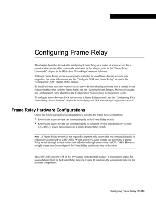
![IV-154 Wide-Area Networking Configuration Guide
Frame Relay Configuration Task List
FINAL DRAFT CISCO CONFIDENTIAL
Figure 28 Typical Frame Relay Configuration
The Frame Relay interface actually consists of one physical connection between the network server
and the switch that provides the service. This single physical connection provides direct connectivity
to each device on a network, such as a StrataCom FastPacket wide-area network (WAN).
Frame Relay Configuration Task List
There are required, basic steps you must follow to enable Frame Relay for your network. In addition,
you can customize Frame Relay for your particular network needs and monitor Frame Relay
connections. The following sections outline these tasks. The tasks in the first two sections are
required.
• Enable Frame Relay Encapsulation on an Interface
• Configure Dynamic or Static Address Mapping
• Configure the LMI
• Configure Frame Relay Switched Virtual Circuits
• Configure Frame Relay Traffic Shaping
• Customize Frame Relay for Your Network
• Monitor the Frame Relay Connections
See the “Frame Relay Configuration Examples” section at the end of this chapter for ideas of how
to configure Frame Relay on your network. See the “Frame Relay Commands” chapter in the
Wide-Area Networking Command Reference for information about the commands listed in the tasks.
Enable Frame Relay Encapsulation on an Interface
To set Frame Relay encapsulation at the interface level, perform the following tasks beginning in
global configuration mode:
1. This command is documented in the “Interface Commands” chapter in the Configuration Fundamentals Command
Reference.
Task Command
Specify the serial interface, and enter interface
configuration mode.
interface serial number1
Enable Frame Relay, and specify the encapsulation
method.
encapsulation frame-relay [ietf]
Router DSU/CSU
V.35
S2304
Public Frame
Relay network
4-wire T1
Router
V.35](data:image/gif;base64,R0lGODlhAQABAIAAAAAAAP///yH5BAEAAAAALAAAAAABAAEAAAIBRAA7)