Arduino_CSE ece ppt for working and principal of arduino.ppt
960649.pdf
1. 40 RD.5C.A2.05 DanfossA/S,11-2000
Presostatos diferenciales,
tipos MP 54, 55 y 55A
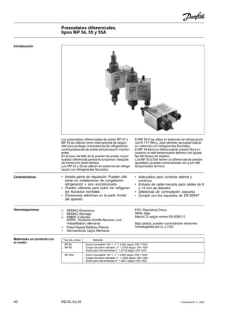
Los presostatos diferenciales de aceite MP 54 y
MP 55 se utilizan como interruptores de seguri-
dad para proteger compresores de refrigeración
contra presiones de aceite de lubricación insufici-
entes.
En el caso de fallo de la presión de aceite, el pre-
sostato diferencial parará el compresor después
de transcurrir cierto tiempo.
Los MP 54 y 55 se utilizan en sistemas de refrige-
ración con refrigerantes fluorados.
El MP 55 A se utiliza en sistemas de refrigeración
con R 717 (NH3), pero también se puede utilizar
en sistemas con refrigerantes fluorados.
El MP 54 tiene un diferencial de presión fijo e in-
corpora un relé temporizador térmico con ajuste
fijo del tiempo de disparo.
Los MP 55 y 55A tienen un diferencial de presión
ajustable y pueden suministrarse con y sin relé
temporizador térmico.
Introducción
• Amplia gama de regulación: Pueden utili-
zarse en instalaciones de congelación,
refrigeración y aire acondicionado.
• Pueden utilizarse para todos los refrigeran-
tes fluorados normales.
• Conexiones eléctricas en la parte frontal
del aparato.
Características • Adecuados para corriente alterna y
continua.
• Entrada de cable roscada para cables de 6
a 14 mm de diámetro
• Diferencial de conmutación pequeña
• Cumple con los requisitos de EN 60947
Homologaciones M DEMKO, Dinamarca
O NEMKO, Noruega
W FIMKO, Finlandia
DSRK, Deutsche-Schiffs-Revision und
-Klassifikation, Alemania
P Polski Rejestr Statków, Polonia
F Germanischer Lloyd, Alemania
EZU, República Checa
RINA, Italia
Marca CE según norma EN 60947-5
Bajo pedido, pueden suministrarse versiones
homologadas por UL y CSA.
Materiales en contacto con
el medio
Tipo de unidad Material
MP 54 Acero inoxidable 19/11, n° 1.4306 según DIN 17440
MP 55 Chapa de acero estirada, n° 1.0338 según DIN 1624
Acero para herramientas n° 1.0718 según DIN 1651
MP 55A Acero inoxidable 19/11, n° 1.4306 según DIN 17440
Chapa de acero estirada, n° 1.0338 según DIN 1624
Acero para herramientas n° 1.0401 según DIN 1652
2. DanfossA/S,11-2000 RD.5C.A2.05 41
Presostatos diferenciales, tipos MP 54, 55 y 55A
MP 54 Fijo 0.65 0.2 −1 → +12 02) B 060B0297
Fijo 0.65 0.2 −1 → +12 45 A 060B0166
Fijo 0.9 0.2 −1 → +12 60 A 060B0167
Fijo 0.65 0.2 −1 → +12 90 A 060B0168
Fijo 0.65 0.2 −1 → +12 120 A 060B01693)
MP 55 0.3 → 4.5 0.2 −1 → +12 45 A 060B0170 060B0133
0.3 → 4.5 0.2 −1 → +12 60 A 060B0171 060B0134 060B0188
0.3 → 4.5 0.2 −1 → +12 60 A 060B01781)
0.3 → 4.5 0.2 −1 → +12 90 A 060B0172
0.3 → 4.5 0.2 −1 → +12 120 A 060B0173 060B0136
0.3 → 4.5 0.2 −1 → +12 02) B 060B0299 060B0295
0.65 → 4.5 0.4 −1 → +12 02) C 060B02944)
Tensión de control
230 V ó 115 V, c.a. o c.c.
Variación de tensión admisible
+10 →−15%
Presión de trabajo máxima
PB = 17 bar
Presión de prueba máxima
p' = 22 bar
Compensación de temperatura
El relé temporizador tiene compensación de
temperatura en la gama −40 a 60°C
Entrada de cable roscada
Pg 13.5
Diámetro del cable
6 → 14 mm
Datos técnicos Temperatura máxima de los fuelles
100 °C
Protección
IP 20 según IEC 529
Cargas de los contactos
Tipo A:
En los contactos M-S de salida del relé
temporizador:
AC15:2 A, 250 V
DC13: 0.2 A, 250 V
Tipo B sin relé temporizador
AC15: 0.1 A, 250 V
DC13: 12 W, 125 V
Tipo C sin relé temporizador
AC1:10 A, 250 V
AC3: 4 A, 250V
DC13: 12 W, 125 V
Pedidos
N° de código
Conexión
abocardada
Carga de los
contactos
(ver datos
técnicos)
Diferencial
de
conmutación
máxima
∆p bar
∆p bar
Diferencial
Tipo
Para refrigerantes fluorados
Gama de
funcionamiento,
lado de baja
presión
bar
1 m tubo
capilar
1/4" soldar
ODF
1/4"/6 mm
Conector por
anillo de
corte
(cutting ring)
6 mm
Tiempo de
apertura del
relé tem-
porizador
s
Para refrigerantes fluorados y R 717 (NH3)
N° de código
Conexión
Carga de los
contactos
(ver datos
técnicos)
Diferencial de
conmutación
máxima
∆p bar
Diferencial
Tipo ∅ 6,5 /
∅ 10 mm
manguito
soldado
Conector por
anillo de corte
(cutting ring)
6 mm
Gama de
funcionamiento,
lado de baja
presión
bar
Tiempo de
apertura del
relé tem-
porizador
s
∆p bar
MP 55A 0.3 → 4.5 0.2 −1 → +12 45 A 060B0174 060B0182
0.3 → 4.5 0.2 −1 → +12 60 A 060B0175 060B0183
0.3 → 4.5 0.2 −1 → +12 60 A 060B0179 1)
0.3 → 4.5 0.2 −1 → +12 90 A 060B0176 060B0184
0.3 → 4.5 0.2 −1 → +12 120 A 060B0177 060B0185
0.3 → 4.5 0.2 −1 → +12 0 2) B 060B0298 2) 060B0296
1 )Con luz piloto de funcionamiento que permanece encendida durante el funcionamiento normal.
Nota: si la luz piloto se apaga, el compresor no debe seguir funcionando un tiempo superior al de apertura del relé.
2 )Las versiones sin relé temporizador son para aplicaciones en las que se necesita un relé temporizador externo, quizá
con un tiempo de apertura distinto del especificado.
3 )El 60B069 cumple las especificaciones Copeland. Pueden suministrarse versiones homologadas por UL.
4 )Homologado según la norma EN 6097-4, -5.
3. Danfoss 9/96
Design The operation of the pressure control is
conditional only on the differential pressure, i.e.
the difference in pressure between the two
counteracting bellows, whereas it is independent
of the absolute pressure acting on both bellows.
The MP 55 and 55A can be set for different
differential pressures by the setting disc (3).The
set differential pressure can be read from the
internal scale.
The MP 54 has a fixed differential and has no
pressure setting disc.The factory-set differential
pressure is stamped on the front plate of the
control.
MP 55
Terminology Differential range
The pressure difference between LP and OIL
connections within which the control can be set
to operate.
Scale reading
The differential between the oil pump pressure
and the pressure in the crankcase that exists at
the moment the contact system cuts in current
to the time relay on falling oil pressure.
Operating range
The pressure range on the LP connection within
which the control can operate.
Contact differential
The pressure rise above the set differential
pressure (scale reading) necessary to cut off
current to the time relay.
Release time
The period for which the differential pressure
control allows the compressor to run with too low
an oil pressure during start-up and operation.
If there is no oil pressure on starting, or if the oil
pressure falls below the set pressure during
operation, the compressor will stop after the
release time has elapsed.
The electrical circuit is divided into two completely
separate circuits, a safety circuit and an
operational circuit.
Function The timer (e) in the safety circuit is activated
when the effective lubricating oil pressure, the oil
differential pressure (the difference between the
oil pump pressure and suction pressure), is lower
than the set value.
The timer is deactivated when the oil differential
pressure is more than the set value plus the
contact differential.
1. Connection to pressure side of
lubrication system, OIL
2. Connection to suction side of
refrigeration plant, LP
3. Setting disc
4. Reset buttom
5. Test device
Electrical diagram
Differential pressure controls, type MP 54, 55 and 55A
Catalogue RK.00.H5.02 - Page 314
4. Danfoss 9/96
The two diagrams below explain the terms "oil
differential pressure" and "contact differential",
both have to be considered when using oil
differential pressure controls.
Function
(continued)
The first diagram shows the function of the
differential control during start; the second shows
the function of the control during operation.
Pos. A: Normal start-up
The lubricating oil pressure is built up during start to the set/
fixed differential plus the contact differential, before the
timer cuts out (in this example, after 45 seconds). At point A
contactsT1-T2 open and timer (e) is stopped, i.e. normal
lubricating oil conditions for the compressor have been
established.
Pos. B: The lubricating oil pressure does not reach the set/
fixed differential plus the contact differential before the timer
period elapses. At point B the timer cuts out operational
circuit L-M and the compressor stops.
If a signal source is connected to terminal S, it will be
activated. Restart can only be performed after about
2 minutes by activation of the reset button, provided the
cause of the fault has been determined.
Pos. C: The lubricating oil pressure falls during operation
to a value lower than the set/fixed differential.
At point C, safety circuitT1-T2 cuts in and the timer is
activated.
Pos. D: The lubricating oil pressure reaches the set/fixed
differential plus the contact differential before the timer
period elapses.
At point D, safety circuitT1-T2 cuts out and the timer is
stopped, i.e. normal lubricating oil conditions for the
compressor have been established.
Pos. E: The lubricating oil pressure falls to a value lower
than the set/fixed differential during operation.
At point E, safety circuitT1-T2 cuts in and the timer is
activated.
Pos. F: The lubricating oil pressure remains lower than the
set/fixed differential. At point F the timer cuts out operational
circuit L-M and the compressor stops.
If a signal source is connected to terminal S, it will be
activated. Restart can only be performed after about 2
minutes by activation of the reset button, provided the
cause of the fault has been determined.
After start-up
It is important that a function check should be made to
ensure that the differential pressure control is operating as
it should.This check can be made by pressing the test
device (inside the unit on the left hand side).
When the test device is pressed down and held in this
position the compressor motor should stop after the release
time determined by the time relay has elapsed.
During operation
On start-up
Differential pressure controls, type MP 54, 55 and 55A
Catalogue RK.00.H5.02 - Page 315
5. Danfoss 9/96
Dimensions and weight
MP 54, 55
Weight
MP 55A approx. 0.8 kg
Differential pressure controls, type MP 54, 55 and 55A
Catalogue RK.00.H5.02 - Page 316