SlideShare a Scribd company logo
1 of 17
Download to read offline
GDP80DC, GDP90DC, GDP100DC, GDP100DCS, GDP120DC (GDP190DC,
GDP210DC, GDP230DC, GDP230DCS, GDP250DC, GDP280DC) (E876);
GDP130EC, GDP140EC, GDP160EC (GDP300EC, GDP330EC, GDP360EC)
(E877)
SERVICE MANUAL CONTENTS
SECTION
PART
NUMBER
YRM
NUMBER
REV
DATE
OPERATOR'S CAB........................................................................................................ 550033400 0100 YRM 1390 11/13
CAB HEATER................................................................................................................. 550033398 0100 YRM 1459 08/12
FRAME............................................................................................................................ 550035500 0100 YRM 1496 06/11
CUMMINS ENGINE FAULT CODE GUIDE.................................................................... 524211827 0600 YRM 1101 07/14
MULTIPLE ALIGNED COOLING SYSTEM.................................................................... 524300813 0700 YRM 1350 05/12
APC200 FAULT CODE GUIDE...................................................................................... 550022606 1300 YRM 1435 02/12
ZF TRANSMISSION OPERATION AND DIAGNOSTICS............................................... 550035502 1300 YRM 1455 09/13
TRANSMISSION REPAIR (ZF-WG161)......................................................................... 550035503 1300 YRM 1456 08/12
TRANSMISSION REPAIR DANA SPICER..................................................................... 550041025 1300 YRM 1536 08/11
TRANSMISSION OPERATION AND DIAGNOSTICS TE-10 WITH FULL FLOW
RELIEF VALVE.......................................................................................................... 550041030 1300 YRM 1537 03/12
DIFFERENTIAL............................................................................................................... 524150779 1400 YRM 0046 08/12
PLANETARY DRIVE AXLE (WET SYSTEM)................................................................. 524150780 1400 YRM 0944 08/12
PLANETARY DRIVE AXLE (DRY SYSTEM)................................................................. 524150781 1400 YRM 0945 08/11
STEERING SYSTEM...................................................................................................... 550035504 1600 YRM 1479 08/12
DRY BRAKE SYSTEM................................................................................................... 550036815 1800 YRM 1477 05/12
BRAKE AND HYDRAULIC COOLING SYSTEM........................................................... 550035505 1800 YRM 1498 03/13
HYDRAULIC SYSTEM.................................................................................................... 550035506 1900 YRM 1478 11/14
HYDRAULIC CONTROL SYSTEM................................................................................. 550035498 2200 YRM 1481 08/12
ELECTRICAL SYSTEM.................................................................................................. 550035507 2200 YRM 1499 04/11
MAST AND CARRIAGES............................................................................................... 524203754 4000 YRM 1062 08/12
2-STAGE MAST.............................................................................................................. 550088524 4000 YRM 1647 05/14
METRIC AND INCH (SAE) FASTENERS....................................................................... 524150797 8000 YRM 0231 10/13
ASSEMBLY GUIDE........................................................................................................ 524230692 8000 YRM 1181 12/14
PERIODIC MAINTENANCE............................................................................................ 550035509 8000 YRM 1475 08/12
DIAGRAMS..................................................................................................................... 550035508 8000 YRM 1500 06/11
CAPACITIES AND SPECIFICATIONS........................................................................... 550035510 8000 YRM 1501 07/13
Service information for Cummins diesel engines can be ordered through the Hyster Literature Distribution Center.
PART NO. 550035493 (12/14)
General
This YRM describes the functions of the cab and the
replacement instructions for the cab components. See
Figure 1. Some of the described components are
options that may not be present on each cab. The
operation of the various switches and controls can be
found in the Operating Manual.
The description and repair instructions for the heater
assembly are in Cab Heater (Prior to Oct. 2008)
0100YRM1458 for lift trucks built prior to October,
2008, and in Cab Heater 0100YRM1459 for lift trucks
built after October, 2008.
The remove and replace instructions for the cab as an
assembly are in the frame YRM specific to each
model lift truck.
Information on systems that are related to the cab are
in YRM for the Electrical System, Hydraulic System,
Brake System, Steering System and Diagrams
specific to each model lift truck.
Before making any repairs to the lift truck, complete
the following procedures:
1. Place the lift truck on a solid, level surface.
2. Lower the mast completely and tilt forward.
3. Place the shift lever in NEUTRAL.
4. Apply the parking brake.
5. Shut down the engine.
0100 YRM 1390 General
1
1. HEATER SECTION
2. INCHING PEDAL
3. BRAKE PEDAL
4. ACCELERATOR PEDAL
5. STEERING COLUMN
6. FRONT, REAR, AND TOP WINDOWS
7. FRONT, REAR, AND TOP WIPER ASSEMBLIES
8. INTEGRATED OVERHEAD GUARD
9. OPERATOR'S CONSOLE, CONTROLS, AND
ARMREST
10. AIR CONDITIONING CONDENSER, DRYER,
AND FAN ASSEMBLY (OPTIONAL)
11. SEAT
Figure 1. Operator's Cab
Description of Operation 0100 YRM 1390
2
Description of Operation
CAB STRUCTURE
The cab frame is a welded structure. The overhead
guard is an integral part of the cab frame. See Fig-
ure 1. In order to maintain maximum overhead protec-
tion, changes to the cab frame and integrated over-
head guard are not allowed. There are two cab op-
tions: an open cab and a closed cab. The closed cab
features windows and wipers, doors, a heater, and
optional air conditioning. Both cab types feature inte-
rior components.
CAB TILT SYSTEM
On lift trucks with a cab tilt system, the cab can tilt to
the right-hand side, providing service access to the
engine compartment and components under the cab.
The cab tilt system consists of a cab support frame,
cab tilt cylinder, cab tilt hand pump assembly, cab
latches, and an optional electrical cab tilt pump. See
Figure 2.
The cab is attached to the lift truck in the lowered po-
sition by the cab support pivots on the right-hand
frame channel, the two cab latches on the left-hand
frame channel, and the cab tilt cylinder.
Hydraulic pressure is required to unlock the cab
latches and extend the cab tilt cylinder. The cab can
be raised by rotating the cab tilt hand pump direc-
tional valve clockwise and operating the cab tilt hand
pump. See Figure 3. To lower the cab from the raised
position, rotate the cab tilt hand pump directional
valve counterclockwise and operating the cab tilt hand
pump. The cab tilt cylinder retracts to lower the cab.
The optional electrical cab tilt pump is push-button op-
erated. See Raising and Lowering Cab, Raise Cab,
Figure 8.
NOTE: If the optional electrical cab tilt pump is inop-
erable, the cab can be raised or lowered by using the
manually operated cab tilt hand pump.
A. PULL DIRECTION OF THE TILT LATCH RE-
LEASE
1. CAB SUPPORT FRAME
2. CAB TILT HAND PUMP
3. CAB LATCH
4. CAB TILT CYLINDER
Figure 2. Cab Tilt System
A. LOWER
B. RAISE
1. PUMP LEVER CONNECTION
2. PUMP DIRECTIONAL VALVE
Figure 3. Cab Tilt Hand Pump
0100 YRM 1390 Description of Operation
3
When the cab has been raised to the partially open
position, the safety latch will engage with a retainer
plate that is welded to the frame. To raise or lower the
cab after the safety latch has engaged, pull and hold
the tilt latch release and raise or lower the cab until
the safety latch has passed the retainer plate.
Just before the fully open position is reached, move-
ment becomes gravity-controlled by the weight of the
cab. The cab is in the fully open position when the
cab tilt cylinder is fully extended.
Cab Tilt System, Raise
When the directional valve is in the raise position, the
pump push port and pump pull port are connected to
each other. See Figure 4.
Hydraulic pressure is transferred to the cab latches
and both the piston and rod side of the cab tilt cylin-
der. Hydraulic oil extruded at the rod side enters the
piston side of the cylinder through the directional
valve in the hand pump. The end of stroke is deter-
mined by a retaining ring in the cab tilt cylinder.
Cab Tilt System, Lower
When the directional valve is in the lower position, the
pump push port is connected to the pump reservoir
through a reservoir check valve. The reservoir check
valve retains enough pressure to keep the cab locks
open. The pump pull port is connected to the hand
pump. While the hand pump provides sufficient pres-
sure, the cylinder check valve will raise to allow the oil
at the piston side of the cylinder to return to the reser-
voir. The cylinder cannot lower when there is insuffi-
cient pressure at the pull connection.
When the piston has reached the free fall area, the oil
at the piston side will escape to the rod side and the
cab will drop under the influence of its own weight.
When the cab drops, the oil in the cab lock cylinders
is pushed out through the reservoir check valve. After
the cab has dropped, the cab is locked into position
by the cab latches.
Description of Operation 0100 YRM 1390
4
1. ROD AREA
2. CAB TILT CYLINDER
3. FREE FALL INTERCONNECTION
4. CHECK VALVE
5. PULL
6. ELECTRIC CAB TILT PUMP (OPTIONAL)
7. RESERVOIR
8. RELIEF VALVE
9. CAB TILT HAND PUMP
10. RESERVOIR CHECK VALVE
11. LOWER
12. PUMP DIRECTIONAL VALVE
13. RAISE
14. LATCH
15. PUSH
Figure 4. Cab Tilt System
0100 YRM 1390 Description of Operation
5
Oil Filling for Cab Tilt System
CAUTION
When oil is added to the cab tilt system, place an
oil absorbing material around the fill cap before
lowering the cab. Excess oil may bleed out of the
relief valve, which is located in the fill cap.
NOTE: If the oil level is low, the cab will not tilt/raise
completely.
NOTE: If the cab is lowered, perform Step 1. If the
cab is raised, go to Step 2.
1. Tilt/Raise raise the cab until it locks in the partially
open position. Refer to the section Raising and
Lowering Cab.
2. Lower the cab until it locks in the partially open
position. Refer to the section Raising and Lower-
ing Cab.
3. Place the pump lever connection in the fully down
position to create easy access to the fill cap. See
Figure 5.
1. FILL CAP
2. PUMP LEVER CONNECTION
Figure 5. Hand Pump
4. Remove the fill cap. See Figure 5.
5. Add hydraulic oil through the filler opening until
the level is within 30 to 35 mm (1.18 to 1.38 in.) of
the top of the reservoir. See Figure 6. For your lift
truck, refer to the appropriate Periodic Mainte-
nance YRMfor the correct hydraulic oil specifica-
tion.
Figure 6. Cab Tilt Label
6. Install the fill cap. See Figure 5.
7. Tilt/raise the cab and make sure the maximum til-
ted/raised (fully opened) position can be reached.
Refer to the section Raising and Lowering Cab.
8. If necessary, repeat Step 1 through Step 7.
9. Lower the cab until it is in the fully lowered posi-
tion and completely latched. Refer to the section
Raising and Lowering Cab.
Oil Filling for Cab Tilt System 0100 YRM 1390
6
Raising and Lowering Cab
RAISE CAB
WARNING
Make sure no one is under the cab when tilting/
raising or lowering the cab, or serious personal
injury may occur.
WARNING
Before doing any work under the cab, always
make sure the cab is fully tilted/raised, or if parti-
ally open, is locked with the tilt latch, or serious
personal injury may occur.
CAUTION
Cab damage may occur if the mast is not com-
pletely tilted forward.
1. Tilt the mast fully forward.
2. Remove all unsecured items from the cab.
3. Close and securely latch the left-hand and right-
hand cab doors.
4. Clear all obstacles from the right-hand side of the
lift truck. Provide a minimum of 2 m (7 ft) clear-
ance space.
5. Use the pump lever to turn the pump directional
valve clockwise to the "Tilt/Raise" position. See
Figure 7.
6. Operate the pump with the pump lever (or push-
button, if equipped with an electric pump), until
the cab locks in the partially open position. See
Figure 8.
NOTE: Just before the fully open position is reached,
movement becomes gravity-controlled by the weight
of the cab.
7. Pull the tilt latch release and continue to tilt/raise
the cab to the fully open position. See Figure 8.
NOTE: If the cab will not fully tilt/raise, lower the cab
until the cab locks in the partially open position, and
check the oil level. Refer to the section Oil Filling for
Cab Tilt System.
A. LOWER B. RAISE
1. PUMP LEVER CONNECTION
2. PUMP DIRECTIONAL VALVE
Figure 7. Pump and Direction Valve
1. CAB
2. FRAME
3. TILT LATCH RELEASE KNOB
4. ELECTRIC CAB TILT PUSH-BUTTON (OP-
TIONAL)
5. PUMP LEVER
Figure 8. Pump Lever and Tilt Latch Release Knob
0100 YRM 1390 Raising and Lowering Cab
7
LOWER CAB
WARNING
Make sure no one is under the cab when raising
or lowering the cab, or serious personal injury
may occur.
WARNING
Before doing any work under the cab, always
make sure the cab is fully tilted/raised, or if parti-
ally open, is locked with the tilt latch, or serious
personal injury may occur.
CAUTION
Cab damage may occur if the mast is not com-
pletely tilted forward.
1. Make sure all foreign items/tools are removed
from under the cab.
2. Use the pump lever to turn the pump directional
valve counterclockwise to the "Lower" position.
See Figure 7.
3. Operate the pump with the pump lever (or push-
button, if equipped), until the cab locks in the par-
tially open position. See Figure 8.
4. Pull the tilt latch release knob and continue to
lower the cab until the cab is in the fully lowered
and latched position.
Cab Door Assembly
CAB DOOR
Remove
1. Open the sliding windows.
2. Attach a lift strap at the left-hand and right-hand
side of the sliding windows inside the sliding win-
dow frame. Place a cushion between the sliding
window frame and the lift straps (left-hand and
right-hand sides) to prevent damage.
3. Position the cab door at a 90° angle to the frame,
so the cab door can be lifted out the hinges.
CAUTION
Use caution when lifting the cab door to avoid
damage to the cab frame.
4. Lift the cab door out of the cab door hinges. See
Figure 9.
5. Move the cab door away from the lift truck and
place it on the ground.
6. Close the sliding windows.
Install
1. Open the sliding windows.
2. Attach a lift strap to the left-hand and right-hand
side of the sliding windows inside the sliding win-
dow frame. Place a cushion between the sliding
window frame and the lift straps (left-hand and
right-hand sides) to prevent damage.
3. Raise the cab door and place it in position above
the hinges.
4. Slowly lower the cab door until the cab door is
seated on the hinges.
5. Remove the lift strap.
6. Make sure the cab door is opening, closing, and
moving properly on the hinges.
7. Make sure the locking system functions properly.
NOTE: Adjust one hinge at a time.
8. If necessary, adjust the hinge location when the
door is closed. Door clearance must be evenly
divided around the door and door opening of the
cab.
9. Loosen the three capscrews and use a nylon
hammer to adjust the hinge. Retighten the cap-
screws.
10. If necessary, adjust the door striker pin. Refer to
the section Door Striker Pin Adjustment.
Cab Door Assembly 0100 YRM 1390
8
A. VIEW TURNED 90° COUNTERCLOCKWISE
1. DOOR HINGE
2. DOOR PUSH-BUTTON
3. DOOR RELEASE
4. DOOR LATCH
5. DOOR HANDLE
Figure 9. Cab Door
DOOR HINGE
Remove
1. Remove the cab door. See the section Cab
DoorRemove.
2. Mark the location of the two hinges on the cab
frame.
3. Remove the six capscrews retaining the two
hinges to the cab frame and remove the two
hinges. See Figure 10.
Install
1. Position the two hinges to the cab frame as
marked and install the six capscrews to retain the
hinges to the cab frame.
2. Install the cab door. Refer to the section Cab
DoorInstall.
3. Make sure the locking system functions properly.
NOTE: Adjust one hinge at a time.
1. DOOR HINGE
2. CAPSCREW
3. CAB FRAME
Figure 10. Door Hinge
0100 YRM 1390 Cab Door Assembly
9
4. If necessary, adjust the hinge location when the
door is closed.
5. Loosen the three capscrews and use a nylon
hammer to adjust the hinge. Retighten the cap-
screws.
DOOR STRIKER PIN
Door Striker Pin Adjustment
1. Make sure the door hinges are correctly installed.
2. Loosen the securing nut that retains the door
striker pin to the cab frame. See Figure 11.
3. Place the door striker pin in the expected latching
position.
4. Push and hold the release button and close the
door with normal force so that the door is posi-
tioned correctly in the door opening of the cab.
5. Open the door with the release button still en-
gaged.
6. Carefully tighten the securing nut that retains the
door striker pin to the cab frame.
7. Close the door and make sure the door is cor-
rectly seated against the door seals.
8. If necessary, repeat Step 1 through Step 7.
1. CAB FRAME
2. SECURING NUT
3. DOOR STRIKER PIN
Figure 11. Door Striker Pin
DOOR LATCH
Remove
1. Remove the capscrew and washer that retain the
plastic cover to the door latch. See Figure 12.
2. Remove the two capscrews that retain the door
latch to the door frame.
3. Disconnect the connector rod from the door latch
attached to the door release.
Install
1. Connect the connector rod to the door latch at-
tached to the door release.
2. Install the two capscrews to retain the door latch
to the door frame.
3. Install the capscrew and washer that retain the
plastic cover to the door latch.
4. Make sure the locking system functions correctly.
1. CAPSCREW
2. WASHER
3. PLASTIC COVER
4. CAPSCREW
5. DOOR LATCH
6. CAB DOOR
7. CONNECTOR ROD
Figure 12. Door Latch
Cab Door Assembly 0100 YRM 1390
10
Thank you very much for
your reading. Please Click
Here. Then Get COMPLETE
MANUAL. NO WAITING
NOTE:
If there is no response to
click on the link above,
please download the PDF
document first and then
click on it.
DOOR HANDLE
Remove
1. Remove the door latch. Refer to the section Door
LatchRemove.
2. Remove the plastic plug at the inside of the door
frame. See Figure 13.
3. Remove the capscrew and washer that retain the
door handle, through the hole from the plastic
plug.
4. Remove the large nut and washer that retain the
door handle on the release button side of the door
handle.
5. Remove the door handle and two rubber cush-
ions.
Install
1. Position the door handle and two rubber cushions
on the door. See Figure 13.
2. Install the washer and large nut on the release
button side of the door handle.
1. WASHER
2. CAPSCREW
3. PLASTIC PLUG
4. CAB DOOR
5. RUBBER CUSHION (LARGE)
6. DOOR HANDLE
7. RUBBER CUSHION (SMALL)
Figure 13. Door Handle
3. Install the washer and capscrew through the hole
from the plastic plug.
4. Install the plastic plug at the inside of the door
frame.
5. Install the latch. Refer to the section Door
LatchInstall.
6. Make sure the locking system functions correctly.
DOOR RELEASE
Remove
1. Remove the door latch. Refer to the section Door
LatchRemove.
2. Remove the capscrew that retains the door re-
lease inside the bar located at the inside of the
door frame. See Figure 15.
3. Remove the connector rod and door release from
inside the bar.
1. CAPSCREW
2. DOOR RELEASE
3. CONNECTOR ROD
4. CAB DOOR
Figure 14. Door Release
0100 YRM 1390 Cab Door Assembly
11
4. Disconnect the connector rod from the door re-
lease.
Install
1. Connect the connector rod to the door release.
See Figure 14.
2. Install the connector and door release inside the
bar, located at the inside of the door frame.
3. Install the capscrew that retains the door release
inside the bar.
4. Install the door latch. Refer to the section Door
LatchInstall.
DOOR PUSH BUTTON
Remove
1. Remove the three plastic caps from the nuts loca-
ted at the inside of the door frame. See Figure 15.
2. Remove the three nuts, washers, and capscrews
that retain the door holder (push button), washer,
and seal to the door frame.
Install
1. Install the three capscrews, washers, and nuts
that retain the door holder (push button), washer,
and seal to the door frame. Hand tighten the nuts.
See Figure 15.
2. Position the cab door in the locking system.
3. Tighten the three nuts.
4. Make sure the door holder is positioned properly
by placing the door in the lock system. Adjust the
door holder (push button) as needed.
5. Install the three plastic caps to the nuts located at
the inside of the door frame.
1. CAB DOOR
2. WASHER
3. SEAL
4. DOOR HOLDER (PUSH BUTTON)
5. WASHER
6. NUT
7. CAPSCREW
Figure 15. Door Push Button
Cab Tilt System
ELECTRIC TILT PUMP
Remove
1. Tilt/raise the cab to the fully open position. Refer
to the section Raising and Lowering Cab.
2. Disconnect the electrical connector, located at the
left-hand panel, from the cab tilt push-button. See
Raising and Lowering Cab, Raise Cab, Figure 8.
3. Remove the two capscrews and washers that re-
tain the left-hand panel to the frame and remove
the left-hand panel.
4. Disconnect the electrical connector from the elec-
trical tilt pump.
5. Tag and disconnect the two hydraulic hoses from
the electrical tilt pump and place plugs on the
hose ends.
6. Remove the two nuts that retain the bracket with
the electrical tilt pump to the frame.
7. Remove the bracket with the electrical tilt pump
from the frame.
8. Remove the two capscrews that retain the electri-
cal tilt pump to the bracket.
Cab Tilt System 0100 YRM 1390
12
9. Remove the electrical tilt pump from the bracket.
Install
1. Position the electrical tilt pump on the bracket.
2. Install the two capscrews that retain the electrical
tilt pump on the bracket.
3. Position the bracket with the electrical tilt pump on
the frame.
4. Install the two nuts that retain the bracket with the
electrical tilt pump to the frame.
5. Remove the plugs and connect the two hoses to
the electrical tilt pump.
6. Connect the electrical connector to the electrical
tilt pump.
7. Position the left-hand panel on the frame and in-
stall the two capscrews and washers to retain the
panel to the frame.
8. Connect the electrical connector to the cab tilt
push-button. See Raising and Lowering Cab,
Raise Cab, Figure 8.
9. Lower the cab to the fully lowered and latched po-
sition. Refer to the section Raising and Lowering
Cab.
10. Operate the electric tilt pump to check for leaks
and to remove air from the cab tilt system.
11. Check the hydraulic oil level. Refer to the section
Oil Filling for Cab Tilt System.
12. Operate the cab tilt system to check for correct
operation.
HAND PUMP
Remove
1. Tilt/raise the cab to the fully open position. Refer
to the section Raising and Lowering Cab.
2. If equipped, disconnect the electrical connector
located at the left-hand panel, from the cab tilt
push-button. See Raising and Lowering Cab,
Raise Cab, Figure 8.
3. Remove the two capscrews and washers that re-
tain the left-hand panel to the frame and remove
the left-hand panel.
4. Remove the two capscrews and washers that re-
tain the hand pump to the frame. See Figure 16.
NOTE: Keep the hydraulic hose connection locations
from the hand pump facing upward to avoid spilling
hydraulic oil.
5. Tag and disconnect the three hydraulic hoses and
place plugs on the three hose ends. See Fig-
ure 16.
Install
1. Remove the plugs from the three hose ends and
connect the three hydraulic hoses to the hand
pump. See Figure 16.
2. Position the hand pump on the frame and install
the two capscrews and washers that retain the
hand pump to the frame. See Figure 16.
3. Position the left-hand panel to the frame and in-
stall the two capscrews and washers to retain the
left-hand panel to the frame.
4. If equipped, connect the electrical connector to
the cab tilt push-button. See Raising and Lower-
ing Cab, Raise Cab, Figure 8.
5. Lower the cab to the fully lowered and latched po-
sition. Refer to the section Raising and Lowering
Cab.
6. Remove the fill cap of the hand pump and fill the
reservoir with hydraulic oil. Refer to the section
Oil Filling for Cab Tilt System.
7. Make sure the cab tilt system functions correctly.
0100 YRM 1390 Cab Tilt System
13
A. 180 DEGREES TURNED
1. FRAME
2. HAND PUMP
3. HYDRAULIC HOSE
4. WASHER
5. CAPSCREW
Figure 16. Hand Pump
Cab Tilt System 0100 YRM 1390
14
CAB TILT CYLINDER
Remove
1. Tilt/raise the cab until it locks in the partially open
position. Refer to the section Raising and Lower-
ing Cab.
2. Place wooden blocks between the frame and the
cab to prevent the cab from suddenly lowering.
3. Tag and disconnect the two hydraulic hoses from
the cab tilt cylinder and install caps on the hy-
draulic fittings and plugs in the hydraulic hoses.
See Figure 18.
4. Remove the snap ring from the pin that retains
the cab tilt cylinder to the frame. See Figure 17.
5. Remove the snap ring from the pin that retains
the cab tilt cylinder to the cab tilt frame.
6. Remove the cab tilt cylinder from the pins and re-
move the cab tilt cylinder from under the frame.
Disassemble
1. Place the cab tilt cylinder in a horizontal position
with the fittings pointing downward in a vise with
soft jaws.
2. Place a drain pan under the fittings.
3. Remove the caps from the fittings and drain the
hydraulic oil from the cab tilt cylinder.
4. Remove the wiper from the cylinder shell. See
Figure 18.
5. Press the gland inside the cylinder shell until the
gland retaining ring is free.
6. Remove the gland retaining ring.
CAUTION
Be careful not to damage the finished surface of
the piston rod when removing the piston rod as-
sembly from the cylinder shell in a horizontal po-
sition.
7. Remove the piston rod assembly from the cylin-
der shell by pulling it out of the cylinder shell.
CAUTION
Be careful not to damage the grooves when re-
moving O-rings, sleeve, U-cup, and retaining
rings.
8. Remove the shaft retaining ring (10,Figure 18)
that retains the piston to the piston rod.
9. Remove the piston from the piston rod.
1. CAB TILT FRAME
2. SNAP RING
3. CAB TILT CYLINDER
4. PIN
5. FRAME
Figure 17. Cab Tilt Cylinder
0100 YRM 1390 Cab Tilt System
15

More Related Content

What's hot

Bt 50 en repair manual
Bt 50 en repair manualBt 50 en repair manual
Bt 50 en repair manualpacho916
 
Yamaha outboard f60 ceht service repair manual sn1000001
Yamaha outboard f60 ceht service repair manual sn1000001Yamaha outboard f60 ceht service repair manual sn1000001
Yamaha outboard f60 ceht service repair manual sn1000001明 浩
 
Caterpillar cat gc20 k forklift lift trucks service repair manual snat82c 000...
Caterpillar cat gc20 k forklift lift trucks service repair manual snat82c 000...Caterpillar cat gc20 k forklift lift trucks service repair manual snat82c 000...
Caterpillar cat gc20 k forklift lift trucks service repair manual snat82c 000...jkskjdkm
 
Hyster f003 (h3.00 js europe) forklift service repair manual
Hyster f003 (h3.00 js europe) forklift service repair manualHyster f003 (h3.00 js europe) forklift service repair manual
Hyster f003 (h3.00 js europe) forklift service repair manualfjjsekfksmem
 
Hyster c177 (h2.50 xl europe) forklift service repair manual
Hyster c177 (h2.50 xl europe) forklift service repair manualHyster c177 (h2.50 xl europe) forklift service repair manual
Hyster c177 (h2.50 xl europe) forklift service repair manualfjskefkksem
 
Catálogo de peças retro escavadeira case 580 l serie2 (r1) brz
Catálogo  de peças retro escavadeira case 580 l serie2  (r1) brzCatálogo  de peças retro escavadeira case 580 l serie2  (r1) brz
Catálogo de peças retro escavadeira case 580 l serie2 (r1) brzJoel Nunes
 
Hmc l4 kb9 sm 20090824 (1)
Hmc l4 kb9 sm 20090824 (1)Hmc l4 kb9 sm 20090824 (1)
Hmc l4 kb9 sm 20090824 (1)Artem Malitskiy
 
Jcb t4 f 444 elec engine (4 cyl) service repair manual
Jcb t4 f 444 elec engine (4 cyl) service repair manualJcb t4 f 444 elec engine (4 cyl) service repair manual
Jcb t4 f 444 elec engine (4 cyl) service repair manualfusefjsekkemm
 
Vnx.su laguna-2000-электросхемы-техническая-нота-8157a
Vnx.su laguna-2000-электросхемы-техническая-нота-8157aVnx.su laguna-2000-электросхемы-техническая-нота-8157a
Vnx.su laguna-2000-электросхемы-техническая-нота-8157areno-rez
 
Caterpillar cat c13 industrial engine (prefix jr9) service repair manual (jr9...
Caterpillar cat c13 industrial engine (prefix jr9) service repair manual (jr9...Caterpillar cat c13 industrial engine (prefix jr9) service repair manual (jr9...
Caterpillar cat c13 industrial engine (prefix jr9) service repair manual (jr9...ifkkdmdmdm
 
2 cargador fronta 950 h cat
2 cargador fronta 950 h cat2 cargador fronta 950 h cat
2 cargador fronta 950 h catraymond linares
 
Manual de serviço cargotod cabecote
Manual de serviço cargotod cabecoteManual de serviço cargotod cabecote
Manual de serviço cargotod cabecoteThiago Huari
 
Yale d809 glc035 vx lift truck service repair manual
Yale d809 glc035 vx lift truck service repair manualYale d809 glc035 vx lift truck service repair manual
Yale d809 glc035 vx lift truck service repair manualjksjekmd
 
2006 lexus is250 service repair manual
2006 lexus is250 service repair manual2006 lexus is250 service repair manual
2006 lexus is250 service repair manualofpsdjksemmds
 
Komatsu SAA6D114E-2 Diesel Engine Service Repair Manual
Komatsu SAA6D114E-2 Diesel Engine Service Repair ManualKomatsu SAA6D114E-2 Diesel Engine Service Repair Manual
Komatsu SAA6D114E-2 Diesel Engine Service Repair Manualufjjsejfkemem
 

What's hot (20)

Bt 50 en repair manual
Bt 50 en repair manualBt 50 en repair manual
Bt 50 en repair manual
 
Yamaha outboard f60 ceht service repair manual sn1000001
Yamaha outboard f60 ceht service repair manual sn1000001Yamaha outboard f60 ceht service repair manual sn1000001
Yamaha outboard f60 ceht service repair manual sn1000001
 
Caterpillar cat gc20 k forklift lift trucks service repair manual snat82c 000...
Caterpillar cat gc20 k forklift lift trucks service repair manual snat82c 000...Caterpillar cat gc20 k forklift lift trucks service repair manual snat82c 000...
Caterpillar cat gc20 k forklift lift trucks service repair manual snat82c 000...
 
Hyster f003 (h3.00 js europe) forklift service repair manual
Hyster f003 (h3.00 js europe) forklift service repair manualHyster f003 (h3.00 js europe) forklift service repair manual
Hyster f003 (h3.00 js europe) forklift service repair manual
 
Hyster c177 (h2.50 xl europe) forklift service repair manual
Hyster c177 (h2.50 xl europe) forklift service repair manualHyster c177 (h2.50 xl europe) forklift service repair manual
Hyster c177 (h2.50 xl europe) forklift service repair manual
 
Catálogo de peças retro escavadeira case 580 l serie2 (r1) brz
Catálogo  de peças retro escavadeira case 580 l serie2  (r1) brzCatálogo  de peças retro escavadeira case 580 l serie2  (r1) brz
Catálogo de peças retro escavadeira case 580 l serie2 (r1) brz
 
Modefer
ModeferModefer
Modefer
 
Hmc l4 kb9 sm 20090824 (1)
Hmc l4 kb9 sm 20090824 (1)Hmc l4 kb9 sm 20090824 (1)
Hmc l4 kb9 sm 20090824 (1)
 
Bt 50 en
Bt 50 enBt 50 en
Bt 50 en
 
Jcb t4 f 444 elec engine (4 cyl) service repair manual
Jcb t4 f 444 elec engine (4 cyl) service repair manualJcb t4 f 444 elec engine (4 cyl) service repair manual
Jcb t4 f 444 elec engine (4 cyl) service repair manual
 
Vnx.su laguna-2000-электросхемы-техническая-нота-8157a
Vnx.su laguna-2000-электросхемы-техническая-нота-8157aVnx.su laguna-2000-электросхемы-техническая-нота-8157a
Vnx.su laguna-2000-электросхемы-техническая-нота-8157a
 
Caterpillar cat c13 industrial engine (prefix jr9) service repair manual (jr9...
Caterpillar cat c13 industrial engine (prefix jr9) service repair manual (jr9...Caterpillar cat c13 industrial engine (prefix jr9) service repair manual (jr9...
Caterpillar cat c13 industrial engine (prefix jr9) service repair manual (jr9...
 
MF4283
MF4283MF4283
MF4283
 
2 cargador fronta 950 h cat
2 cargador fronta 950 h cat2 cargador fronta 950 h cat
2 cargador fronta 950 h cat
 
Manual de serviço cargotod cabecote
Manual de serviço cargotod cabecoteManual de serviço cargotod cabecote
Manual de serviço cargotod cabecote
 
Tabela de parede linha diesel
Tabela de parede linha dieselTabela de parede linha diesel
Tabela de parede linha diesel
 
Yale d809 glc035 vx lift truck service repair manual
Yale d809 glc035 vx lift truck service repair manualYale d809 glc035 vx lift truck service repair manual
Yale d809 glc035 vx lift truck service repair manual
 
2006 lexus is250 service repair manual
2006 lexus is250 service repair manual2006 lexus is250 service repair manual
2006 lexus is250 service repair manual
 
Komatsu SAA6D114E-2 Diesel Engine Service Repair Manual
Komatsu SAA6D114E-2 Diesel Engine Service Repair ManualKomatsu SAA6D114E-2 Diesel Engine Service Repair Manual
Komatsu SAA6D114E-2 Diesel Engine Service Repair Manual
 
Zf error codes (1)
Zf error codes (1)Zf error codes (1)
Zf error codes (1)
 

More from fjjskkefksme

John deere 664 row crop headers service repair manual (tm4530)
John deere 664 row crop headers service repair manual (tm4530)John deere 664 row crop headers service repair manual (tm4530)
John deere 664 row crop headers service repair manual (tm4530)fjjskkefksme
 
John deere 665 r row crop headers service repair manual (tm4530)
John deere 665 r row crop headers service repair manual (tm4530)John deere 665 r row crop headers service repair manual (tm4530)
John deere 665 r row crop headers service repair manual (tm4530)fjjskkefksme
 
John deere 666 row crop headers service repair manual (tm4530)
John deere 666 row crop headers service repair manual (tm4530)John deere 666 row crop headers service repair manual (tm4530)
John deere 666 row crop headers service repair manual (tm4530)fjjskkefksme
 
John deere 666 r row crop headers service repair manual (tm4530)
John deere 666 r row crop headers service repair manual (tm4530)John deere 666 r row crop headers service repair manual (tm4530)
John deere 666 r row crop headers service repair manual (tm4530)fjjskkefksme
 
John deere 7200 front fold max emerge 2 drawn conservation planters service r...
John deere 7200 front fold max emerge 2 drawn conservation planters service r...John deere 7200 front fold max emerge 2 drawn conservation planters service r...
John deere 7200 front fold max emerge 2 drawn conservation planters service r...fjjskkefksme
 
John deere fg18 swing to tree disk saw felling head service repair manual (tm...
John deere fg18 swing to tree disk saw felling head service repair manual (tm...John deere fg18 swing to tree disk saw felling head service repair manual (tm...
John deere fg18 swing to tree disk saw felling head service repair manual (tm...fjjskkefksme
 
John deere fs series heads swing to tree disc saw heads service repair manual...
John deere fs series heads swing to tree disc saw heads service repair manual...John deere fs series heads swing to tree disc saw heads service repair manual...
John deere fs series heads swing to tree disc saw heads service repair manual...fjjskkefksme
 
Caterpillar cat d350 e articulated truck (prefix 9lr) service repair manual (...
Caterpillar cat d350 e articulated truck (prefix 9lr) service repair manual (...Caterpillar cat d350 e articulated truck (prefix 9lr) service repair manual (...
Caterpillar cat d350 e articulated truck (prefix 9lr) service repair manual (...fjjskkefksme
 
Caterpillar cat d350 d articulated truck (prefix 9rf) service repair manual (...
Caterpillar cat d350 d articulated truck (prefix 9rf) service repair manual (...Caterpillar cat d350 d articulated truck (prefix 9rf) service repair manual (...
Caterpillar cat d350 d articulated truck (prefix 9rf) service repair manual (...fjjskkefksme
 
Caterpillar cat d350 d articulated truck (prefix 3aj) service repair manual (...
Caterpillar cat d350 d articulated truck (prefix 3aj) service repair manual (...Caterpillar cat d350 d articulated truck (prefix 3aj) service repair manual (...
Caterpillar cat d350 d articulated truck (prefix 3aj) service repair manual (...fjjskkefksme
 
Caterpillar cat d350 d articulated truck (prefix 1hk) service repair manual (...
Caterpillar cat d350 d articulated truck (prefix 1hk) service repair manual (...Caterpillar cat d350 d articulated truck (prefix 1hk) service repair manual (...
Caterpillar cat d350 d articulated truck (prefix 1hk) service repair manual (...fjjskkefksme
 
Caterpillar cat d250 e ii articulated truck (prefix 4ps) service repair manua...
Caterpillar cat d250 e ii articulated truck (prefix 4ps) service repair manua...Caterpillar cat d250 e ii articulated truck (prefix 4ps) service repair manua...
Caterpillar cat d250 e ii articulated truck (prefix 4ps) service repair manua...fjjskkefksme
 
Caterpillar cat d250 e articulated truck (prefix 5tn) service repair manual (...
Caterpillar cat d250 e articulated truck (prefix 5tn) service repair manual (...Caterpillar cat d250 e articulated truck (prefix 5tn) service repair manual (...
Caterpillar cat d250 e articulated truck (prefix 5tn) service repair manual (...fjjskkefksme
 
Caterpillar cat d250 d articulated truck (prefix 9mg) service repair manual (...
Caterpillar cat d250 d articulated truck (prefix 9mg) service repair manual (...Caterpillar cat d250 d articulated truck (prefix 9mg) service repair manual (...
Caterpillar cat d250 d articulated truck (prefix 9mg) service repair manual (...fjjskkefksme
 
Caterpillar cat d250 d articulated truck (prefix 6ng) service repair manual (...
Caterpillar cat d250 d articulated truck (prefix 6ng) service repair manual (...Caterpillar cat d250 d articulated truck (prefix 6ng) service repair manual (...
Caterpillar cat d250 d articulated truck (prefix 6ng) service repair manual (...fjjskkefksme
 
Caterpillar cat d250 b articulated dump truck (prefix 5wd) service repair man...
Caterpillar cat d250 b articulated dump truck (prefix 5wd) service repair man...Caterpillar cat d250 b articulated dump truck (prefix 5wd) service repair man...
Caterpillar cat d250 b articulated dump truck (prefix 5wd) service repair man...fjjskkefksme
 
Caterpillar cat d44 b articulated dump truck (prefix 8sd) service repair manu...
Caterpillar cat d44 b articulated dump truck (prefix 8sd) service repair manu...Caterpillar cat d44 b articulated dump truck (prefix 8sd) service repair manu...
Caterpillar cat d44 b articulated dump truck (prefix 8sd) service repair manu...fjjskkefksme
 
Caterpillar cat d35 hp articulated dump truck (prefix 3fd) service repair man...
Caterpillar cat d35 hp articulated dump truck (prefix 3fd) service repair man...Caterpillar cat d35 hp articulated dump truck (prefix 3fd) service repair man...
Caterpillar cat d35 hp articulated dump truck (prefix 3fd) service repair man...fjjskkefksme
 
Caterpillar cat d35 c articulated dump truck (prefix 2gd) service repair manu...
Caterpillar cat d35 c articulated dump truck (prefix 2gd) service repair manu...Caterpillar cat d35 c articulated dump truck (prefix 2gd) service repair manu...
Caterpillar cat d35 c articulated dump truck (prefix 2gd) service repair manu...fjjskkefksme
 
Caterpillar cat d30 d articulated truck (prefix 9rf) service repair manual (9...
Caterpillar cat d30 d articulated truck (prefix 9rf) service repair manual (9...Caterpillar cat d30 d articulated truck (prefix 9rf) service repair manual (9...
Caterpillar cat d30 d articulated truck (prefix 9rf) service repair manual (9...fjjskkefksme
 

More from fjjskkefksme (20)

John deere 664 row crop headers service repair manual (tm4530)
John deere 664 row crop headers service repair manual (tm4530)John deere 664 row crop headers service repair manual (tm4530)
John deere 664 row crop headers service repair manual (tm4530)
 
John deere 665 r row crop headers service repair manual (tm4530)
John deere 665 r row crop headers service repair manual (tm4530)John deere 665 r row crop headers service repair manual (tm4530)
John deere 665 r row crop headers service repair manual (tm4530)
 
John deere 666 row crop headers service repair manual (tm4530)
John deere 666 row crop headers service repair manual (tm4530)John deere 666 row crop headers service repair manual (tm4530)
John deere 666 row crop headers service repair manual (tm4530)
 
John deere 666 r row crop headers service repair manual (tm4530)
John deere 666 r row crop headers service repair manual (tm4530)John deere 666 r row crop headers service repair manual (tm4530)
John deere 666 r row crop headers service repair manual (tm4530)
 
John deere 7200 front fold max emerge 2 drawn conservation planters service r...
John deere 7200 front fold max emerge 2 drawn conservation planters service r...John deere 7200 front fold max emerge 2 drawn conservation planters service r...
John deere 7200 front fold max emerge 2 drawn conservation planters service r...
 
John deere fg18 swing to tree disk saw felling head service repair manual (tm...
John deere fg18 swing to tree disk saw felling head service repair manual (tm...John deere fg18 swing to tree disk saw felling head service repair manual (tm...
John deere fg18 swing to tree disk saw felling head service repair manual (tm...
 
John deere fs series heads swing to tree disc saw heads service repair manual...
John deere fs series heads swing to tree disc saw heads service repair manual...John deere fs series heads swing to tree disc saw heads service repair manual...
John deere fs series heads swing to tree disc saw heads service repair manual...
 
Caterpillar cat d350 e articulated truck (prefix 9lr) service repair manual (...
Caterpillar cat d350 e articulated truck (prefix 9lr) service repair manual (...Caterpillar cat d350 e articulated truck (prefix 9lr) service repair manual (...
Caterpillar cat d350 e articulated truck (prefix 9lr) service repair manual (...
 
Caterpillar cat d350 d articulated truck (prefix 9rf) service repair manual (...
Caterpillar cat d350 d articulated truck (prefix 9rf) service repair manual (...Caterpillar cat d350 d articulated truck (prefix 9rf) service repair manual (...
Caterpillar cat d350 d articulated truck (prefix 9rf) service repair manual (...
 
Caterpillar cat d350 d articulated truck (prefix 3aj) service repair manual (...
Caterpillar cat d350 d articulated truck (prefix 3aj) service repair manual (...Caterpillar cat d350 d articulated truck (prefix 3aj) service repair manual (...
Caterpillar cat d350 d articulated truck (prefix 3aj) service repair manual (...
 
Caterpillar cat d350 d articulated truck (prefix 1hk) service repair manual (...
Caterpillar cat d350 d articulated truck (prefix 1hk) service repair manual (...Caterpillar cat d350 d articulated truck (prefix 1hk) service repair manual (...
Caterpillar cat d350 d articulated truck (prefix 1hk) service repair manual (...
 
Caterpillar cat d250 e ii articulated truck (prefix 4ps) service repair manua...
Caterpillar cat d250 e ii articulated truck (prefix 4ps) service repair manua...Caterpillar cat d250 e ii articulated truck (prefix 4ps) service repair manua...
Caterpillar cat d250 e ii articulated truck (prefix 4ps) service repair manua...
 
Caterpillar cat d250 e articulated truck (prefix 5tn) service repair manual (...
Caterpillar cat d250 e articulated truck (prefix 5tn) service repair manual (...Caterpillar cat d250 e articulated truck (prefix 5tn) service repair manual (...
Caterpillar cat d250 e articulated truck (prefix 5tn) service repair manual (...
 
Caterpillar cat d250 d articulated truck (prefix 9mg) service repair manual (...
Caterpillar cat d250 d articulated truck (prefix 9mg) service repair manual (...Caterpillar cat d250 d articulated truck (prefix 9mg) service repair manual (...
Caterpillar cat d250 d articulated truck (prefix 9mg) service repair manual (...
 
Caterpillar cat d250 d articulated truck (prefix 6ng) service repair manual (...
Caterpillar cat d250 d articulated truck (prefix 6ng) service repair manual (...Caterpillar cat d250 d articulated truck (prefix 6ng) service repair manual (...
Caterpillar cat d250 d articulated truck (prefix 6ng) service repair manual (...
 
Caterpillar cat d250 b articulated dump truck (prefix 5wd) service repair man...
Caterpillar cat d250 b articulated dump truck (prefix 5wd) service repair man...Caterpillar cat d250 b articulated dump truck (prefix 5wd) service repair man...
Caterpillar cat d250 b articulated dump truck (prefix 5wd) service repair man...
 
Caterpillar cat d44 b articulated dump truck (prefix 8sd) service repair manu...
Caterpillar cat d44 b articulated dump truck (prefix 8sd) service repair manu...Caterpillar cat d44 b articulated dump truck (prefix 8sd) service repair manu...
Caterpillar cat d44 b articulated dump truck (prefix 8sd) service repair manu...
 
Caterpillar cat d35 hp articulated dump truck (prefix 3fd) service repair man...
Caterpillar cat d35 hp articulated dump truck (prefix 3fd) service repair man...Caterpillar cat d35 hp articulated dump truck (prefix 3fd) service repair man...
Caterpillar cat d35 hp articulated dump truck (prefix 3fd) service repair man...
 
Caterpillar cat d35 c articulated dump truck (prefix 2gd) service repair manu...
Caterpillar cat d35 c articulated dump truck (prefix 2gd) service repair manu...Caterpillar cat d35 c articulated dump truck (prefix 2gd) service repair manu...
Caterpillar cat d35 c articulated dump truck (prefix 2gd) service repair manu...
 
Caterpillar cat d30 d articulated truck (prefix 9rf) service repair manual (9...
Caterpillar cat d30 d articulated truck (prefix 9rf) service repair manual (9...Caterpillar cat d30 d articulated truck (prefix 9rf) service repair manual (9...
Caterpillar cat d30 d articulated truck (prefix 9rf) service repair manual (9...
 

Recently uploaded

如何办理爱尔兰都柏林大学毕业证(UCD毕业证) 成绩单原版一比一
如何办理爱尔兰都柏林大学毕业证(UCD毕业证) 成绩单原版一比一如何办理爱尔兰都柏林大学毕业证(UCD毕业证) 成绩单原版一比一
如何办理爱尔兰都柏林大学毕业证(UCD毕业证) 成绩单原版一比一mjyguplun
 
꧁༒☬ 7042364481 (Call Girl) In Dwarka Delhi Escort Service In Delhi Ncr☬༒꧂
꧁༒☬ 7042364481 (Call Girl) In Dwarka Delhi Escort Service In Delhi Ncr☬༒꧂꧁༒☬ 7042364481 (Call Girl) In Dwarka Delhi Escort Service In Delhi Ncr☬༒꧂
꧁༒☬ 7042364481 (Call Girl) In Dwarka Delhi Escort Service In Delhi Ncr☬༒꧂Hot Call Girls In Sector 58 (Noida)
 
FULL ENJOY - 9953040155 Call Girls in Sector 61 | Noida
FULL ENJOY - 9953040155 Call Girls in Sector 61 | NoidaFULL ENJOY - 9953040155 Call Girls in Sector 61 | Noida
FULL ENJOY - 9953040155 Call Girls in Sector 61 | NoidaMalviyaNagarCallGirl
 
(办理学位证)墨尔本大学毕业证(Unimelb毕业证书)成绩单留信学历认证原版一模一样
(办理学位证)墨尔本大学毕业证(Unimelb毕业证书)成绩单留信学历认证原版一模一样(办理学位证)墨尔本大学毕业证(Unimelb毕业证书)成绩单留信学历认证原版一模一样
(办理学位证)墨尔本大学毕业证(Unimelb毕业证书)成绩单留信学历认证原版一模一样whjjkkk
 
call girls in G.T.B. Nagar (DELHI) 🔝 >༒9953330565🔝 genuine Escort Service 🔝✔️✔️
call girls in  G.T.B. Nagar (DELHI) 🔝 >༒9953330565🔝 genuine Escort Service 🔝✔️✔️call girls in  G.T.B. Nagar (DELHI) 🔝 >༒9953330565🔝 genuine Escort Service 🔝✔️✔️
call girls in G.T.B. Nagar (DELHI) 🔝 >༒9953330565🔝 genuine Escort Service 🔝✔️✔️9953056974 Low Rate Call Girls In Saket, Delhi NCR
 
Call Girl Service Global Village Dubai +971509430017 Independent Call Girls G...
Call Girl Service Global Village Dubai +971509430017 Independent Call Girls G...Call Girl Service Global Village Dubai +971509430017 Independent Call Girls G...
Call Girl Service Global Village Dubai +971509430017 Independent Call Girls G...kexey39068
 
定制昆士兰大学毕业证(本硕)UQ学位证书原版一比一
定制昆士兰大学毕业证(本硕)UQ学位证书原版一比一定制昆士兰大学毕业证(本硕)UQ学位证书原版一比一
定制昆士兰大学毕业证(本硕)UQ学位证书原版一比一fjjhfuubb
 
UNIT-III-TRANSMISSION SYSTEMS REAR AXLES
UNIT-III-TRANSMISSION SYSTEMS REAR AXLESUNIT-III-TRANSMISSION SYSTEMS REAR AXLES
UNIT-III-TRANSMISSION SYSTEMS REAR AXLESDineshKumar4165
 
Digamma / CertiCon Company Presentation
Digamma / CertiCon Company  PresentationDigamma / CertiCon Company  Presentation
Digamma / CertiCon Company PresentationMihajloManjak
 
Dubai Call Girls Services Call 09900000000
Dubai Call Girls Services Call 09900000000Dubai Call Girls Services Call 09900000000
Dubai Call Girls Services Call 09900000000Komal Khan
 
VIP Kolkata Call Girl Kasba 👉 8250192130 Available With Room
VIP Kolkata Call Girl Kasba 👉 8250192130  Available With RoomVIP Kolkata Call Girl Kasba 👉 8250192130  Available With Room
VIP Kolkata Call Girl Kasba 👉 8250192130 Available With Roomdivyansh0kumar0
 
What Could Cause A VW Tiguan's Radiator Fan To Stop Working
What Could Cause A VW Tiguan's Radiator Fan To Stop WorkingWhat Could Cause A VW Tiguan's Radiator Fan To Stop Working
What Could Cause A VW Tiguan's Radiator Fan To Stop WorkingEscondido German Auto
 
UNIT-IV-STEERING, BRAKES AND SUSPENSION SYSTEMS.pptx
UNIT-IV-STEERING, BRAKES AND SUSPENSION SYSTEMS.pptxUNIT-IV-STEERING, BRAKES AND SUSPENSION SYSTEMS.pptx
UNIT-IV-STEERING, BRAKES AND SUSPENSION SYSTEMS.pptxDineshKumar4165
 
原版1:1复刻俄亥俄州立大学毕业证OSU毕业证留信学历认证
原版1:1复刻俄亥俄州立大学毕业证OSU毕业证留信学历认证原版1:1复刻俄亥俄州立大学毕业证OSU毕业证留信学历认证
原版1:1复刻俄亥俄州立大学毕业证OSU毕业证留信学历认证jdkhjh
 
BLUE VEHICLES the kids picture show 2024
BLUE VEHICLES the kids picture show 2024BLUE VEHICLES the kids picture show 2024
BLUE VEHICLES the kids picture show 2024AHOhOops1
 
John Deere 300 3029 4039 4045 6059 6068 Engine Operation and Service Manual
John Deere 300 3029 4039 4045 6059 6068 Engine Operation and Service ManualJohn Deere 300 3029 4039 4045 6059 6068 Engine Operation and Service Manual
John Deere 300 3029 4039 4045 6059 6068 Engine Operation and Service ManualExcavator
 
Digamma - CertiCon Team Skills and Qualifications
Digamma - CertiCon Team Skills and QualificationsDigamma - CertiCon Team Skills and Qualifications
Digamma - CertiCon Team Skills and QualificationsMihajloManjak
 
2024 TOP 10 most fuel-efficient vehicles according to the US agency
2024 TOP 10 most fuel-efficient vehicles according to the US agency2024 TOP 10 most fuel-efficient vehicles according to the US agency
2024 TOP 10 most fuel-efficient vehicles according to the US agencyHyundai Motor Group
 
call girls in Jama Masjid (DELHI) 🔝 >༒9953330565🔝 genuine Escort Service 🔝✔️✔️
call girls in Jama Masjid (DELHI) 🔝 >༒9953330565🔝 genuine Escort Service 🔝✔️✔️call girls in Jama Masjid (DELHI) 🔝 >༒9953330565🔝 genuine Escort Service 🔝✔️✔️
call girls in Jama Masjid (DELHI) 🔝 >༒9953330565🔝 genuine Escort Service 🔝✔️✔️9953056974 Low Rate Call Girls In Saket, Delhi NCR
 

Recently uploaded (20)

如何办理爱尔兰都柏林大学毕业证(UCD毕业证) 成绩单原版一比一
如何办理爱尔兰都柏林大学毕业证(UCD毕业证) 成绩单原版一比一如何办理爱尔兰都柏林大学毕业证(UCD毕业证) 成绩单原版一比一
如何办理爱尔兰都柏林大学毕业证(UCD毕业证) 成绩单原版一比一
 
꧁༒☬ 7042364481 (Call Girl) In Dwarka Delhi Escort Service In Delhi Ncr☬༒꧂
꧁༒☬ 7042364481 (Call Girl) In Dwarka Delhi Escort Service In Delhi Ncr☬༒꧂꧁༒☬ 7042364481 (Call Girl) In Dwarka Delhi Escort Service In Delhi Ncr☬༒꧂
꧁༒☬ 7042364481 (Call Girl) In Dwarka Delhi Escort Service In Delhi Ncr☬༒꧂
 
FULL ENJOY - 9953040155 Call Girls in Sector 61 | Noida
FULL ENJOY - 9953040155 Call Girls in Sector 61 | NoidaFULL ENJOY - 9953040155 Call Girls in Sector 61 | Noida
FULL ENJOY - 9953040155 Call Girls in Sector 61 | Noida
 
(办理学位证)墨尔本大学毕业证(Unimelb毕业证书)成绩单留信学历认证原版一模一样
(办理学位证)墨尔本大学毕业证(Unimelb毕业证书)成绩单留信学历认证原版一模一样(办理学位证)墨尔本大学毕业证(Unimelb毕业证书)成绩单留信学历认证原版一模一样
(办理学位证)墨尔本大学毕业证(Unimelb毕业证书)成绩单留信学历认证原版一模一样
 
call girls in G.T.B. Nagar (DELHI) 🔝 >༒9953330565🔝 genuine Escort Service 🔝✔️✔️
call girls in  G.T.B. Nagar (DELHI) 🔝 >༒9953330565🔝 genuine Escort Service 🔝✔️✔️call girls in  G.T.B. Nagar (DELHI) 🔝 >༒9953330565🔝 genuine Escort Service 🔝✔️✔️
call girls in G.T.B. Nagar (DELHI) 🔝 >༒9953330565🔝 genuine Escort Service 🔝✔️✔️
 
Call Girl Service Global Village Dubai +971509430017 Independent Call Girls G...
Call Girl Service Global Village Dubai +971509430017 Independent Call Girls G...Call Girl Service Global Village Dubai +971509430017 Independent Call Girls G...
Call Girl Service Global Village Dubai +971509430017 Independent Call Girls G...
 
定制昆士兰大学毕业证(本硕)UQ学位证书原版一比一
定制昆士兰大学毕业证(本硕)UQ学位证书原版一比一定制昆士兰大学毕业证(本硕)UQ学位证书原版一比一
定制昆士兰大学毕业证(本硕)UQ学位证书原版一比一
 
UNIT-III-TRANSMISSION SYSTEMS REAR AXLES
UNIT-III-TRANSMISSION SYSTEMS REAR AXLESUNIT-III-TRANSMISSION SYSTEMS REAR AXLES
UNIT-III-TRANSMISSION SYSTEMS REAR AXLES
 
Digamma / CertiCon Company Presentation
Digamma / CertiCon Company  PresentationDigamma / CertiCon Company  Presentation
Digamma / CertiCon Company Presentation
 
Dubai Call Girls Services Call 09900000000
Dubai Call Girls Services Call 09900000000Dubai Call Girls Services Call 09900000000
Dubai Call Girls Services Call 09900000000
 
VIP Kolkata Call Girl Kasba 👉 8250192130 Available With Room
VIP Kolkata Call Girl Kasba 👉 8250192130  Available With RoomVIP Kolkata Call Girl Kasba 👉 8250192130  Available With Room
VIP Kolkata Call Girl Kasba 👉 8250192130 Available With Room
 
What Could Cause A VW Tiguan's Radiator Fan To Stop Working
What Could Cause A VW Tiguan's Radiator Fan To Stop WorkingWhat Could Cause A VW Tiguan's Radiator Fan To Stop Working
What Could Cause A VW Tiguan's Radiator Fan To Stop Working
 
UNIT-IV-STEERING, BRAKES AND SUSPENSION SYSTEMS.pptx
UNIT-IV-STEERING, BRAKES AND SUSPENSION SYSTEMS.pptxUNIT-IV-STEERING, BRAKES AND SUSPENSION SYSTEMS.pptx
UNIT-IV-STEERING, BRAKES AND SUSPENSION SYSTEMS.pptx
 
原版1:1复刻俄亥俄州立大学毕业证OSU毕业证留信学历认证
原版1:1复刻俄亥俄州立大学毕业证OSU毕业证留信学历认证原版1:1复刻俄亥俄州立大学毕业证OSU毕业证留信学历认证
原版1:1复刻俄亥俄州立大学毕业证OSU毕业证留信学历认证
 
BLUE VEHICLES the kids picture show 2024
BLUE VEHICLES the kids picture show 2024BLUE VEHICLES the kids picture show 2024
BLUE VEHICLES the kids picture show 2024
 
John Deere 300 3029 4039 4045 6059 6068 Engine Operation and Service Manual
John Deere 300 3029 4039 4045 6059 6068 Engine Operation and Service ManualJohn Deere 300 3029 4039 4045 6059 6068 Engine Operation and Service Manual
John Deere 300 3029 4039 4045 6059 6068 Engine Operation and Service Manual
 
Digamma - CertiCon Team Skills and Qualifications
Digamma - CertiCon Team Skills and QualificationsDigamma - CertiCon Team Skills and Qualifications
Digamma - CertiCon Team Skills and Qualifications
 
Hot Sexy call girls in Pira Garhi🔝 9953056974 🔝 escort Service
Hot Sexy call girls in Pira Garhi🔝 9953056974 🔝 escort ServiceHot Sexy call girls in Pira Garhi🔝 9953056974 🔝 escort Service
Hot Sexy call girls in Pira Garhi🔝 9953056974 🔝 escort Service
 
2024 TOP 10 most fuel-efficient vehicles according to the US agency
2024 TOP 10 most fuel-efficient vehicles according to the US agency2024 TOP 10 most fuel-efficient vehicles according to the US agency
2024 TOP 10 most fuel-efficient vehicles according to the US agency
 
call girls in Jama Masjid (DELHI) 🔝 >༒9953330565🔝 genuine Escort Service 🔝✔️✔️
call girls in Jama Masjid (DELHI) 🔝 >༒9953330565🔝 genuine Escort Service 🔝✔️✔️call girls in Jama Masjid (DELHI) 🔝 >༒9953330565🔝 genuine Escort Service 🔝✔️✔️
call girls in Jama Masjid (DELHI) 🔝 >༒9953330565🔝 genuine Escort Service 🔝✔️✔️
 

Yale (e877) gdp360 ec lift truck service repair manual

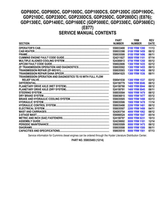
  • 1. GDP80DC, GDP90DC, GDP100DC, GDP100DCS, GDP120DC (GDP190DC, GDP210DC, GDP230DC, GDP230DCS, GDP250DC, GDP280DC) (E876); GDP130EC, GDP140EC, GDP160EC (GDP300EC, GDP330EC, GDP360EC) (E877) SERVICE MANUAL CONTENTS SECTION PART NUMBER YRM NUMBER REV DATE OPERATOR'S CAB........................................................................................................ 550033400 0100 YRM 1390 11/13 CAB HEATER................................................................................................................. 550033398 0100 YRM 1459 08/12 FRAME............................................................................................................................ 550035500 0100 YRM 1496 06/11 CUMMINS ENGINE FAULT CODE GUIDE.................................................................... 524211827 0600 YRM 1101 07/14 MULTIPLE ALIGNED COOLING SYSTEM.................................................................... 524300813 0700 YRM 1350 05/12 APC200 FAULT CODE GUIDE...................................................................................... 550022606 1300 YRM 1435 02/12 ZF TRANSMISSION OPERATION AND DIAGNOSTICS............................................... 550035502 1300 YRM 1455 09/13 TRANSMISSION REPAIR (ZF-WG161)......................................................................... 550035503 1300 YRM 1456 08/12 TRANSMISSION REPAIR DANA SPICER..................................................................... 550041025 1300 YRM 1536 08/11 TRANSMISSION OPERATION AND DIAGNOSTICS TE-10 WITH FULL FLOW RELIEF VALVE.......................................................................................................... 550041030 1300 YRM 1537 03/12 DIFFERENTIAL............................................................................................................... 524150779 1400 YRM 0046 08/12 PLANETARY DRIVE AXLE (WET SYSTEM)................................................................. 524150780 1400 YRM 0944 08/12 PLANETARY DRIVE AXLE (DRY SYSTEM)................................................................. 524150781 1400 YRM 0945 08/11 STEERING SYSTEM...................................................................................................... 550035504 1600 YRM 1479 08/12 DRY BRAKE SYSTEM................................................................................................... 550036815 1800 YRM 1477 05/12 BRAKE AND HYDRAULIC COOLING SYSTEM........................................................... 550035505 1800 YRM 1498 03/13 HYDRAULIC SYSTEM.................................................................................................... 550035506 1900 YRM 1478 11/14 HYDRAULIC CONTROL SYSTEM................................................................................. 550035498 2200 YRM 1481 08/12 ELECTRICAL SYSTEM.................................................................................................. 550035507 2200 YRM 1499 04/11 MAST AND CARRIAGES............................................................................................... 524203754 4000 YRM 1062 08/12 2-STAGE MAST.............................................................................................................. 550088524 4000 YRM 1647 05/14 METRIC AND INCH (SAE) FASTENERS....................................................................... 524150797 8000 YRM 0231 10/13 ASSEMBLY GUIDE........................................................................................................ 524230692 8000 YRM 1181 12/14 PERIODIC MAINTENANCE............................................................................................ 550035509 8000 YRM 1475 08/12 DIAGRAMS..................................................................................................................... 550035508 8000 YRM 1500 06/11 CAPACITIES AND SPECIFICATIONS........................................................................... 550035510 8000 YRM 1501 07/13 Service information for Cummins diesel engines can be ordered through the Hyster Literature Distribution Center. PART NO. 550035493 (12/14)
  • 2. General This YRM describes the functions of the cab and the replacement instructions for the cab components. See Figure 1. Some of the described components are options that may not be present on each cab. The operation of the various switches and controls can be found in the Operating Manual. The description and repair instructions for the heater assembly are in Cab Heater (Prior to Oct. 2008) 0100YRM1458 for lift trucks built prior to October, 2008, and in Cab Heater 0100YRM1459 for lift trucks built after October, 2008. The remove and replace instructions for the cab as an assembly are in the frame YRM specific to each model lift truck. Information on systems that are related to the cab are in YRM for the Electrical System, Hydraulic System, Brake System, Steering System and Diagrams specific to each model lift truck. Before making any repairs to the lift truck, complete the following procedures: 1. Place the lift truck on a solid, level surface. 2. Lower the mast completely and tilt forward. 3. Place the shift lever in NEUTRAL. 4. Apply the parking brake. 5. Shut down the engine. 0100 YRM 1390 General 1
  • 3. 1. HEATER SECTION 2. INCHING PEDAL 3. BRAKE PEDAL 4. ACCELERATOR PEDAL 5. STEERING COLUMN 6. FRONT, REAR, AND TOP WINDOWS 7. FRONT, REAR, AND TOP WIPER ASSEMBLIES 8. INTEGRATED OVERHEAD GUARD 9. OPERATOR'S CONSOLE, CONTROLS, AND ARMREST 10. AIR CONDITIONING CONDENSER, DRYER, AND FAN ASSEMBLY (OPTIONAL) 11. SEAT Figure 1. Operator's Cab Description of Operation 0100 YRM 1390 2
  • 4. Description of Operation CAB STRUCTURE The cab frame is a welded structure. The overhead guard is an integral part of the cab frame. See Fig- ure 1. In order to maintain maximum overhead protec- tion, changes to the cab frame and integrated over- head guard are not allowed. There are two cab op- tions: an open cab and a closed cab. The closed cab features windows and wipers, doors, a heater, and optional air conditioning. Both cab types feature inte- rior components. CAB TILT SYSTEM On lift trucks with a cab tilt system, the cab can tilt to the right-hand side, providing service access to the engine compartment and components under the cab. The cab tilt system consists of a cab support frame, cab tilt cylinder, cab tilt hand pump assembly, cab latches, and an optional electrical cab tilt pump. See Figure 2. The cab is attached to the lift truck in the lowered po- sition by the cab support pivots on the right-hand frame channel, the two cab latches on the left-hand frame channel, and the cab tilt cylinder. Hydraulic pressure is required to unlock the cab latches and extend the cab tilt cylinder. The cab can be raised by rotating the cab tilt hand pump direc- tional valve clockwise and operating the cab tilt hand pump. See Figure 3. To lower the cab from the raised position, rotate the cab tilt hand pump directional valve counterclockwise and operating the cab tilt hand pump. The cab tilt cylinder retracts to lower the cab. The optional electrical cab tilt pump is push-button op- erated. See Raising and Lowering Cab, Raise Cab, Figure 8. NOTE: If the optional electrical cab tilt pump is inop- erable, the cab can be raised or lowered by using the manually operated cab tilt hand pump. A. PULL DIRECTION OF THE TILT LATCH RE- LEASE 1. CAB SUPPORT FRAME 2. CAB TILT HAND PUMP 3. CAB LATCH 4. CAB TILT CYLINDER Figure 2. Cab Tilt System A. LOWER B. RAISE 1. PUMP LEVER CONNECTION 2. PUMP DIRECTIONAL VALVE Figure 3. Cab Tilt Hand Pump 0100 YRM 1390 Description of Operation 3
  • 5. When the cab has been raised to the partially open position, the safety latch will engage with a retainer plate that is welded to the frame. To raise or lower the cab after the safety latch has engaged, pull and hold the tilt latch release and raise or lower the cab until the safety latch has passed the retainer plate. Just before the fully open position is reached, move- ment becomes gravity-controlled by the weight of the cab. The cab is in the fully open position when the cab tilt cylinder is fully extended. Cab Tilt System, Raise When the directional valve is in the raise position, the pump push port and pump pull port are connected to each other. See Figure 4. Hydraulic pressure is transferred to the cab latches and both the piston and rod side of the cab tilt cylin- der. Hydraulic oil extruded at the rod side enters the piston side of the cylinder through the directional valve in the hand pump. The end of stroke is deter- mined by a retaining ring in the cab tilt cylinder. Cab Tilt System, Lower When the directional valve is in the lower position, the pump push port is connected to the pump reservoir through a reservoir check valve. The reservoir check valve retains enough pressure to keep the cab locks open. The pump pull port is connected to the hand pump. While the hand pump provides sufficient pres- sure, the cylinder check valve will raise to allow the oil at the piston side of the cylinder to return to the reser- voir. The cylinder cannot lower when there is insuffi- cient pressure at the pull connection. When the piston has reached the free fall area, the oil at the piston side will escape to the rod side and the cab will drop under the influence of its own weight. When the cab drops, the oil in the cab lock cylinders is pushed out through the reservoir check valve. After the cab has dropped, the cab is locked into position by the cab latches. Description of Operation 0100 YRM 1390 4
  • 6. 1. ROD AREA 2. CAB TILT CYLINDER 3. FREE FALL INTERCONNECTION 4. CHECK VALVE 5. PULL 6. ELECTRIC CAB TILT PUMP (OPTIONAL) 7. RESERVOIR 8. RELIEF VALVE 9. CAB TILT HAND PUMP 10. RESERVOIR CHECK VALVE 11. LOWER 12. PUMP DIRECTIONAL VALVE 13. RAISE 14. LATCH 15. PUSH Figure 4. Cab Tilt System 0100 YRM 1390 Description of Operation 5
  • 7. Oil Filling for Cab Tilt System CAUTION When oil is added to the cab tilt system, place an oil absorbing material around the fill cap before lowering the cab. Excess oil may bleed out of the relief valve, which is located in the fill cap. NOTE: If the oil level is low, the cab will not tilt/raise completely. NOTE: If the cab is lowered, perform Step 1. If the cab is raised, go to Step 2. 1. Tilt/Raise raise the cab until it locks in the partially open position. Refer to the section Raising and Lowering Cab. 2. Lower the cab until it locks in the partially open position. Refer to the section Raising and Lower- ing Cab. 3. Place the pump lever connection in the fully down position to create easy access to the fill cap. See Figure 5. 1. FILL CAP 2. PUMP LEVER CONNECTION Figure 5. Hand Pump 4. Remove the fill cap. See Figure 5. 5. Add hydraulic oil through the filler opening until the level is within 30 to 35 mm (1.18 to 1.38 in.) of the top of the reservoir. See Figure 6. For your lift truck, refer to the appropriate Periodic Mainte- nance YRMfor the correct hydraulic oil specifica- tion. Figure 6. Cab Tilt Label 6. Install the fill cap. See Figure 5. 7. Tilt/raise the cab and make sure the maximum til- ted/raised (fully opened) position can be reached. Refer to the section Raising and Lowering Cab. 8. If necessary, repeat Step 1 through Step 7. 9. Lower the cab until it is in the fully lowered posi- tion and completely latched. Refer to the section Raising and Lowering Cab. Oil Filling for Cab Tilt System 0100 YRM 1390 6
  • 8. Raising and Lowering Cab RAISE CAB WARNING Make sure no one is under the cab when tilting/ raising or lowering the cab, or serious personal injury may occur. WARNING Before doing any work under the cab, always make sure the cab is fully tilted/raised, or if parti- ally open, is locked with the tilt latch, or serious personal injury may occur. CAUTION Cab damage may occur if the mast is not com- pletely tilted forward. 1. Tilt the mast fully forward. 2. Remove all unsecured items from the cab. 3. Close and securely latch the left-hand and right- hand cab doors. 4. Clear all obstacles from the right-hand side of the lift truck. Provide a minimum of 2 m (7 ft) clear- ance space. 5. Use the pump lever to turn the pump directional valve clockwise to the "Tilt/Raise" position. See Figure 7. 6. Operate the pump with the pump lever (or push- button, if equipped with an electric pump), until the cab locks in the partially open position. See Figure 8. NOTE: Just before the fully open position is reached, movement becomes gravity-controlled by the weight of the cab. 7. Pull the tilt latch release and continue to tilt/raise the cab to the fully open position. See Figure 8. NOTE: If the cab will not fully tilt/raise, lower the cab until the cab locks in the partially open position, and check the oil level. Refer to the section Oil Filling for Cab Tilt System. A. LOWER B. RAISE 1. PUMP LEVER CONNECTION 2. PUMP DIRECTIONAL VALVE Figure 7. Pump and Direction Valve 1. CAB 2. FRAME 3. TILT LATCH RELEASE KNOB 4. ELECTRIC CAB TILT PUSH-BUTTON (OP- TIONAL) 5. PUMP LEVER Figure 8. Pump Lever and Tilt Latch Release Knob 0100 YRM 1390 Raising and Lowering Cab 7
  • 9. LOWER CAB WARNING Make sure no one is under the cab when raising or lowering the cab, or serious personal injury may occur. WARNING Before doing any work under the cab, always make sure the cab is fully tilted/raised, or if parti- ally open, is locked with the tilt latch, or serious personal injury may occur. CAUTION Cab damage may occur if the mast is not com- pletely tilted forward. 1. Make sure all foreign items/tools are removed from under the cab. 2. Use the pump lever to turn the pump directional valve counterclockwise to the "Lower" position. See Figure 7. 3. Operate the pump with the pump lever (or push- button, if equipped), until the cab locks in the par- tially open position. See Figure 8. 4. Pull the tilt latch release knob and continue to lower the cab until the cab is in the fully lowered and latched position. Cab Door Assembly CAB DOOR Remove 1. Open the sliding windows. 2. Attach a lift strap at the left-hand and right-hand side of the sliding windows inside the sliding win- dow frame. Place a cushion between the sliding window frame and the lift straps (left-hand and right-hand sides) to prevent damage. 3. Position the cab door at a 90° angle to the frame, so the cab door can be lifted out the hinges. CAUTION Use caution when lifting the cab door to avoid damage to the cab frame. 4. Lift the cab door out of the cab door hinges. See Figure 9. 5. Move the cab door away from the lift truck and place it on the ground. 6. Close the sliding windows. Install 1. Open the sliding windows. 2. Attach a lift strap to the left-hand and right-hand side of the sliding windows inside the sliding win- dow frame. Place a cushion between the sliding window frame and the lift straps (left-hand and right-hand sides) to prevent damage. 3. Raise the cab door and place it in position above the hinges. 4. Slowly lower the cab door until the cab door is seated on the hinges. 5. Remove the lift strap. 6. Make sure the cab door is opening, closing, and moving properly on the hinges. 7. Make sure the locking system functions properly. NOTE: Adjust one hinge at a time. 8. If necessary, adjust the hinge location when the door is closed. Door clearance must be evenly divided around the door and door opening of the cab. 9. Loosen the three capscrews and use a nylon hammer to adjust the hinge. Retighten the cap- screws. 10. If necessary, adjust the door striker pin. Refer to the section Door Striker Pin Adjustment. Cab Door Assembly 0100 YRM 1390 8
  • 10. A. VIEW TURNED 90° COUNTERCLOCKWISE 1. DOOR HINGE 2. DOOR PUSH-BUTTON 3. DOOR RELEASE 4. DOOR LATCH 5. DOOR HANDLE Figure 9. Cab Door DOOR HINGE Remove 1. Remove the cab door. See the section Cab DoorRemove. 2. Mark the location of the two hinges on the cab frame. 3. Remove the six capscrews retaining the two hinges to the cab frame and remove the two hinges. See Figure 10. Install 1. Position the two hinges to the cab frame as marked and install the six capscrews to retain the hinges to the cab frame. 2. Install the cab door. Refer to the section Cab DoorInstall. 3. Make sure the locking system functions properly. NOTE: Adjust one hinge at a time. 1. DOOR HINGE 2. CAPSCREW 3. CAB FRAME Figure 10. Door Hinge 0100 YRM 1390 Cab Door Assembly 9
  • 11. 4. If necessary, adjust the hinge location when the door is closed. 5. Loosen the three capscrews and use a nylon hammer to adjust the hinge. Retighten the cap- screws. DOOR STRIKER PIN Door Striker Pin Adjustment 1. Make sure the door hinges are correctly installed. 2. Loosen the securing nut that retains the door striker pin to the cab frame. See Figure 11. 3. Place the door striker pin in the expected latching position. 4. Push and hold the release button and close the door with normal force so that the door is posi- tioned correctly in the door opening of the cab. 5. Open the door with the release button still en- gaged. 6. Carefully tighten the securing nut that retains the door striker pin to the cab frame. 7. Close the door and make sure the door is cor- rectly seated against the door seals. 8. If necessary, repeat Step 1 through Step 7. 1. CAB FRAME 2. SECURING NUT 3. DOOR STRIKER PIN Figure 11. Door Striker Pin DOOR LATCH Remove 1. Remove the capscrew and washer that retain the plastic cover to the door latch. See Figure 12. 2. Remove the two capscrews that retain the door latch to the door frame. 3. Disconnect the connector rod from the door latch attached to the door release. Install 1. Connect the connector rod to the door latch at- tached to the door release. 2. Install the two capscrews to retain the door latch to the door frame. 3. Install the capscrew and washer that retain the plastic cover to the door latch. 4. Make sure the locking system functions correctly. 1. CAPSCREW 2. WASHER 3. PLASTIC COVER 4. CAPSCREW 5. DOOR LATCH 6. CAB DOOR 7. CONNECTOR ROD Figure 12. Door Latch Cab Door Assembly 0100 YRM 1390 10
  • 12. Thank you very much for your reading. Please Click Here. Then Get COMPLETE MANUAL. NO WAITING NOTE: If there is no response to click on the link above, please download the PDF document first and then click on it.
  • 13. DOOR HANDLE Remove 1. Remove the door latch. Refer to the section Door LatchRemove. 2. Remove the plastic plug at the inside of the door frame. See Figure 13. 3. Remove the capscrew and washer that retain the door handle, through the hole from the plastic plug. 4. Remove the large nut and washer that retain the door handle on the release button side of the door handle. 5. Remove the door handle and two rubber cush- ions. Install 1. Position the door handle and two rubber cushions on the door. See Figure 13. 2. Install the washer and large nut on the release button side of the door handle. 1. WASHER 2. CAPSCREW 3. PLASTIC PLUG 4. CAB DOOR 5. RUBBER CUSHION (LARGE) 6. DOOR HANDLE 7. RUBBER CUSHION (SMALL) Figure 13. Door Handle 3. Install the washer and capscrew through the hole from the plastic plug. 4. Install the plastic plug at the inside of the door frame. 5. Install the latch. Refer to the section Door LatchInstall. 6. Make sure the locking system functions correctly. DOOR RELEASE Remove 1. Remove the door latch. Refer to the section Door LatchRemove. 2. Remove the capscrew that retains the door re- lease inside the bar located at the inside of the door frame. See Figure 15. 3. Remove the connector rod and door release from inside the bar. 1. CAPSCREW 2. DOOR RELEASE 3. CONNECTOR ROD 4. CAB DOOR Figure 14. Door Release 0100 YRM 1390 Cab Door Assembly 11
  • 14. 4. Disconnect the connector rod from the door re- lease. Install 1. Connect the connector rod to the door release. See Figure 14. 2. Install the connector and door release inside the bar, located at the inside of the door frame. 3. Install the capscrew that retains the door release inside the bar. 4. Install the door latch. Refer to the section Door LatchInstall. DOOR PUSH BUTTON Remove 1. Remove the three plastic caps from the nuts loca- ted at the inside of the door frame. See Figure 15. 2. Remove the three nuts, washers, and capscrews that retain the door holder (push button), washer, and seal to the door frame. Install 1. Install the three capscrews, washers, and nuts that retain the door holder (push button), washer, and seal to the door frame. Hand tighten the nuts. See Figure 15. 2. Position the cab door in the locking system. 3. Tighten the three nuts. 4. Make sure the door holder is positioned properly by placing the door in the lock system. Adjust the door holder (push button) as needed. 5. Install the three plastic caps to the nuts located at the inside of the door frame. 1. CAB DOOR 2. WASHER 3. SEAL 4. DOOR HOLDER (PUSH BUTTON) 5. WASHER 6. NUT 7. CAPSCREW Figure 15. Door Push Button Cab Tilt System ELECTRIC TILT PUMP Remove 1. Tilt/raise the cab to the fully open position. Refer to the section Raising and Lowering Cab. 2. Disconnect the electrical connector, located at the left-hand panel, from the cab tilt push-button. See Raising and Lowering Cab, Raise Cab, Figure 8. 3. Remove the two capscrews and washers that re- tain the left-hand panel to the frame and remove the left-hand panel. 4. Disconnect the electrical connector from the elec- trical tilt pump. 5. Tag and disconnect the two hydraulic hoses from the electrical tilt pump and place plugs on the hose ends. 6. Remove the two nuts that retain the bracket with the electrical tilt pump to the frame. 7. Remove the bracket with the electrical tilt pump from the frame. 8. Remove the two capscrews that retain the electri- cal tilt pump to the bracket. Cab Tilt System 0100 YRM 1390 12
  • 15. 9. Remove the electrical tilt pump from the bracket. Install 1. Position the electrical tilt pump on the bracket. 2. Install the two capscrews that retain the electrical tilt pump on the bracket. 3. Position the bracket with the electrical tilt pump on the frame. 4. Install the two nuts that retain the bracket with the electrical tilt pump to the frame. 5. Remove the plugs and connect the two hoses to the electrical tilt pump. 6. Connect the electrical connector to the electrical tilt pump. 7. Position the left-hand panel on the frame and in- stall the two capscrews and washers to retain the panel to the frame. 8. Connect the electrical connector to the cab tilt push-button. See Raising and Lowering Cab, Raise Cab, Figure 8. 9. Lower the cab to the fully lowered and latched po- sition. Refer to the section Raising and Lowering Cab. 10. Operate the electric tilt pump to check for leaks and to remove air from the cab tilt system. 11. Check the hydraulic oil level. Refer to the section Oil Filling for Cab Tilt System. 12. Operate the cab tilt system to check for correct operation. HAND PUMP Remove 1. Tilt/raise the cab to the fully open position. Refer to the section Raising and Lowering Cab. 2. If equipped, disconnect the electrical connector located at the left-hand panel, from the cab tilt push-button. See Raising and Lowering Cab, Raise Cab, Figure 8. 3. Remove the two capscrews and washers that re- tain the left-hand panel to the frame and remove the left-hand panel. 4. Remove the two capscrews and washers that re- tain the hand pump to the frame. See Figure 16. NOTE: Keep the hydraulic hose connection locations from the hand pump facing upward to avoid spilling hydraulic oil. 5. Tag and disconnect the three hydraulic hoses and place plugs on the three hose ends. See Fig- ure 16. Install 1. Remove the plugs from the three hose ends and connect the three hydraulic hoses to the hand pump. See Figure 16. 2. Position the hand pump on the frame and install the two capscrews and washers that retain the hand pump to the frame. See Figure 16. 3. Position the left-hand panel to the frame and in- stall the two capscrews and washers to retain the left-hand panel to the frame. 4. If equipped, connect the electrical connector to the cab tilt push-button. See Raising and Lower- ing Cab, Raise Cab, Figure 8. 5. Lower the cab to the fully lowered and latched po- sition. Refer to the section Raising and Lowering Cab. 6. Remove the fill cap of the hand pump and fill the reservoir with hydraulic oil. Refer to the section Oil Filling for Cab Tilt System. 7. Make sure the cab tilt system functions correctly. 0100 YRM 1390 Cab Tilt System 13
  • 16. A. 180 DEGREES TURNED 1. FRAME 2. HAND PUMP 3. HYDRAULIC HOSE 4. WASHER 5. CAPSCREW Figure 16. Hand Pump Cab Tilt System 0100 YRM 1390 14
  • 17. CAB TILT CYLINDER Remove 1. Tilt/raise the cab until it locks in the partially open position. Refer to the section Raising and Lower- ing Cab. 2. Place wooden blocks between the frame and the cab to prevent the cab from suddenly lowering. 3. Tag and disconnect the two hydraulic hoses from the cab tilt cylinder and install caps on the hy- draulic fittings and plugs in the hydraulic hoses. See Figure 18. 4. Remove the snap ring from the pin that retains the cab tilt cylinder to the frame. See Figure 17. 5. Remove the snap ring from the pin that retains the cab tilt cylinder to the cab tilt frame. 6. Remove the cab tilt cylinder from the pins and re- move the cab tilt cylinder from under the frame. Disassemble 1. Place the cab tilt cylinder in a horizontal position with the fittings pointing downward in a vise with soft jaws. 2. Place a drain pan under the fittings. 3. Remove the caps from the fittings and drain the hydraulic oil from the cab tilt cylinder. 4. Remove the wiper from the cylinder shell. See Figure 18. 5. Press the gland inside the cylinder shell until the gland retaining ring is free. 6. Remove the gland retaining ring. CAUTION Be careful not to damage the finished surface of the piston rod when removing the piston rod as- sembly from the cylinder shell in a horizontal po- sition. 7. Remove the piston rod assembly from the cylin- der shell by pulling it out of the cylinder shell. CAUTION Be careful not to damage the grooves when re- moving O-rings, sleeve, U-cup, and retaining rings. 8. Remove the shaft retaining ring (10,Figure 18) that retains the piston to the piston rod. 9. Remove the piston from the piston rod. 1. CAB TILT FRAME 2. SNAP RING 3. CAB TILT CYLINDER 4. PIN 5. FRAME Figure 17. Cab Tilt Cylinder 0100 YRM 1390 Cab Tilt System 15