Unveiling the Soundscape Music for Psychedelic Experiences
6161103 4.9 further reduction of a force and couple system
1. 4.9 Further Reduction of a
Force and Couple System
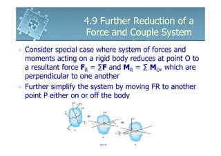
Consider special case where system of forces and
moments acting on a rigid body reduces at point O to
a resultant force FR = ∑F and MR = ∑ MO, which are
perpendicular to one another
Further simplify the system by moving FR to another
point P either on or off the body
2. 4.9 Further Reduction of a
Force and Couple System
Location of P, measured from point O, can be
determined provided FR and MR known
P must lie on the axis bb, which is perpendicular to
the line of action at FR and the aa axis
Distance d satisfies MRo = Frd or d = MRo/Fr
3. 4.9 Further Reduction of a
Force and Couple System
With FR located, it will produce the same resultant
effects on the body
If the system of forces are concurrent, coplanar or
parallel, it can be reduced to a single resultant force
acting
For simplified system, in each case, FR and MRo will
always be perpendicular to each other
4. 4.9 Further Reduction of a
Force and Couple System
Concurrent Force Systems
All the forces act at a point for which there is
no resultant couple moment, so that point P is
automatically specified
5. 4.9 Further Reduction of a
Force and Couple System
Coplanar Force Systems
May include couple moments directed perpendicular
to the plane of forces
Can be reduced to a single resultant force
When each force is moved to any point O in the x-y
plane, it produces a couple moment perpendicular to
the plane
6. 4.9 Further Reduction of a
Force and Couple System
Coplanar Force Systems
For resultant moment,
MRo = ∑M + ∑(r X F)
Resultant moment is perpendicular to resultant force
FR can be positioned a distance d from O to create
this same moment MRo about O
7. 4.9 Further Reduction of a
Force and Couple System
Parallel Force Systems
Include couple moments that are perpendicular to the
forces
Can be reduced to a single resultant force
When each force is moved to any point O in the x-y
plane, it produces a couple moment components only
x and y axes
8. 4.9 Further Reduction of a
Force and Couple System
Parallel Force Systems
For resultant moment,
MRo = ∑MO + ∑(r X F)
Resultant moment is perpendicular to resultant force
FR can be positioned a distance d from O to create
this same moment MRo about O
9. 4.9 Further Reduction of a
Force and Couple System
Three parallel forces acting on the stick can be
replaced a single resultant force FR acting at a
distance d from the grip
To be equivalent,
F R = F 1 + F2 + F3
To find distance d,
FRd = F1d1 + F2d2 +F3d3
10. 4.9 Further Reduction of a
Force and Couple System
Procedure for Analysis
Establish the x, y, z axes and locate the resultant
force an arbitrary distance away from the origin
of the coordinates
Force Summation
For coplanar force system, resolve each force
into x and y components
If the component is directed along the positive x
or y axis, it represent a positive scalar
If the component is directed along the negative x
or y axis, it represent a negative scalar
11. 4.9 Further Reduction of a
Force and Couple System
Procedure for Analysis
Force Summation
Resultant force = sum of all the forces in the
system
Moment Summation
Moment of the resultant moment about point O
= sum of all the couple moment in the system
plus the moments about point O of all the forces
in the system
Moment condition is used to find location of
resultant force from point O
12. 4.9 Further Reduction of a
Force and Couple System
Reduction to a Wrench
In general, the force and couple moment system
acting on a body will reduce to a single resultant
force and a couple moment at o that are not
perpendicular
FR will act at an angle θ from MRo
MRo can be resolved into one perpendicular M┴
and the other M║ parallel to line of action of FR
13. 4.9 Further Reduction of a
Force and Couple System
Reduction to a Wrench
M┴ can be eliminated by moving FR to point P
that lies on the axis bb, which is perpendicular to
both MRo and FR
To maintain equivalency of loading, for distance
from O to P, d = M┴/FR
When FR is applied at P, moment of FR tends to
cause rotation in the same direction as M┴
14. 4.9 Further Reduction of a
Force and Couple System
Reduction to a Wrench
Since M ║ is a free vector, it may be moved to P so that it
is collinear to FR
Combination of collinear force and couple moment is
called a wrench or screw
Axis of wrench has the same line of action as the force
Wrench tends to cause a translation and rotation about
this axis
15. 4.9 Further Reduction of a
Force and Couple System
Reduction to a Wrench
A general force and couple moment system
acting on a body can be reduced to a wrench
Axis of the wrench and the point through which
this axis passes can always be determined
16. 4.9 Further Reduction of a
Force and Couple System
Example 4.16
The beam AE is subjected to a system of coplanar
forces. Determine the magnitude, direction and
location on the beam of a resultant force which is
equivalent to the given system of forces measured
from E
17. 4.9 Further Reduction of a
Force and Couple System
Solution
Force Summation
+ → FRx = ΣFx ;
FRx = 500 cos 60o N + 100 N
= 350.0 N = 350.0 N →
+ → FRy = ΣFy ;
FRy = −500 sin 60o N + 200 N
= −233.0 N = 233.0 N ↓
18. 4.9 Further Reduction of a
Force and Couple System
Solution
For magnitude of resultant force
FR = ( FRx ) 2 + ( FRy ) 2 = (350.0) 2 + (233.0) 2
= 420.5 N
For direction of resultant force
FRy −1 233.0
−1
θ = tan F = tan 350.0
Rx
= 33.7 o
19. 4.9 Further Reduction of a
Force and Couple System
Solution
- Moment Summation
Summation of moments about point E,
M RE = ΣM E ;
233.0 N (d ) + 350 N (0) = (500 sin 60o N )(4m) + (500 cos 60o N )(0m)
− (100 N )(0.5m) − (200 N )(2.5m)
1182.1
d= = 5.07m
233.0
20. 4.9 Further Reduction of a
Force and Couple System
Example 4.17
The jib crane is subjected to three coplanar
forces. Replace this loading by an equivalent
resultant force and specify
where the resultant’s line of
action intersects the column
AB and boom BC.
21. 4.9 Further Reduction of a
Force and Couple System
Solution
Force Summation
+ → FRx = ΣFx ;
3 − 1.75kN
FRx = −2.5kN
5
= −3.25kN = 3.25kN ←
+ → FRy = ΣFy ;
4 − 0.6kN
FRy = −2.5 N
5
= −2.60kN = 2.60 N ↓
22. 4.9 Further Reduction of a
Force and Couple System
Solution
For magnitude of resultant force
FR = (FRx)2 + (FRy)2 = (3.25)2 + (2.60)2
= 4.16kN
For direction of resultant force
−1 FRy −1 2.60
θ = tan
= tan
FRx 3.25
= 38.7o
23. 4.9 Further Reduction of a
Force and Couple System
Solution
Moment Summation
Method 1
Summation of moments about point A,
M RA = ΣM A ;
3.25kN ( y ) + 2.60kN (0)
= 1.75kn(1m) − 0.6kN (0.6m)
3 ( 2.2m) − 2.50kN 4 (1.6m)
+ 2.50kN
5 5
y = 0.458m
24. 4.9 Further Reduction of a
Force and Couple System
Solution
Principle of Transmissibility
M RA = ΣM A ;
3.25kN (2.2m) − 2.60kN ( x)
= 1.75kn(1m) − 0.6kN (0.6m)
3 4
+ 2.50kN (2.2m) − 2.50kN (1.6m)
5 5
x = 2.177m
25. 4.9 Further Reduction of a
Force and Couple System
Solution
Method 2
Take moments about point A,
M RA = ΣM A ;
3.25kN ( y ) − 2.60kN ( x)
= 1.75kn(1m) − 0.6kN (0.6m)
3 4
+ 2.50kN (2.2m) − 2.50kN (1.6m)
5 5
3.25 y − 2.60 x = 1.49
26. 4.9 Further Reduction of a
Force and Couple System
Solution
To find points of intersection, let
x = 0 then y = 0.458m
Along BC, set y = 2.2m then x =
2.177m
27. 4.9 Further Reduction of a
Force and Couple System
Example 4.18
The slab is subjected to four parallel forces.
Determine the magnitude and direction of the
resultant force equivalent to the given force
system and locate its point of application on
the slab.
28. 4.9 Further Reduction of a
Force and Couple System
Solution
Force Summation
+ ↑ FR = ΣF ;
FR = −600 N + 100 N − 400 N − 500 N
= −1400 N = 1400 N ↓
29. 4.9 Further Reduction of a
Force and Couple System
Solution
Moment Summation
M Rx = ΣM x ;
− 1400 N ( y ) = 600 N (0) + 100 N (5m) − 400 N (10m) − 500 N (0)
− 1400 y = −3500
y = 2.50m
M Ry = ΣM y ;
1400 N ( x) = 600 N (8m) − 100 N (6m) + 400 N (0) + 500 N (0)
1400 x = 4200
x = 3.00m
30. 4.9 Further Reduction of a
Force and Couple System
Solution
A force of FR = 1400N placed at point P (3.00m,
2.50m) on the slab is equivalent to the parallel force
system acting on the slab
31. 4.9 Further Reduction of a
Force and Couple System
Example 4.19
Three parallel bolting forces act
on the rim of the circular cover
plate. Determine the magnitude
and direction of a resultant
force equivalent to the given
force system and locate its
point of application, P on the
cover plate.
32. 4.9 Further Reduction of a
Force and Couple System
Solution
Force Summation
r r
FR = ΣF ;
r r r r
FR = −300k − 200k − 150k
r
= {−650k }N
33. 4.9 Further Reduction of a
Force and Couple System
Solution
Moment Summation
r r
M Ro = ΣM O ;
r r r r r r r r
r XFR = rA X (−300k ) + rB X (−200k ) + rC X (−150k )
r r r r r r r
( xi + yj ) X (−650k ) = (0.8i ) X (−300k ) + (−0.8 j ) X (−20k )
r r r
+ (−0.8 sin 45 i + 0.8 cos 45 j ) X (−150k )
o o
r r r r r r
650 xj − 650 yj = 240 j + 160i − 84.85 j − 84.85i
Equating i and j components,
650 x = 240 − 84.85
− 650 y = 160 − 84.85
34. 4.9 Further Reduction of a
Force and Couple System
Solution
Solving, x = 0.239m and y = -0.116m
Negative value of y indicates that the +ve direction is
wrongly assumed
Using right hand rule,
M Ry = ΣM y ;
650 x = 300 N (0.8m) − 150 N (0.8 sin 45o m)
M Rx = ΣM x ;
− 650 x = 200 N (0.8m) − 150 N (0.8 cos 45o m)