Floatless Relay Controls Water Level
•
1 like•4,906 views

This document describes the operation of a floatless relay used to automatically control water levels. It contains diagrams and explanations of different models of floatless relays and their connections. The relays use electrodes at different water level points to control pumps for water supply and discharge operations. Alarms and indicator lights signal various water level conditions.

Recommended
More Related Content
What's hot
What's hot (20)
Viewers also liked
Viewers also liked (8)
More from Eko Kiswanto
More from Eko Kiswanto (20)
Recently uploaded
Recently uploaded (20)
Floatless Relay Controls Water Level
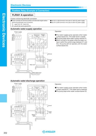
- 1. Electronic Devices Floatless Relay (Example of Connection) Electronic Devices FLR501 A operation Caution concerning electrode connection ●Check carefully the terminal symbols and electrode lengths before ●Use 0V to 100V terminal in the case of 100V AC power supply. performing electrode circuit connection. ●Use 0V to 200V terminal in the case of 200V AC power supply. E1 : upper limit, E2 : lower limit, E3 : ground (be sure to ground E3) Automatic water-supply operation Power supply Operation circuit breaker Molded case Electronic Power relay ●The water-supply pump operates when water circuit × surface leaves E2. (The water level is raised) ●The pump stops when water surface reaches E1. ●When turning on the power while the water sur- face is within the control range (between E1 and E2), the pump will not operate until the water surface leaves E2. Ground Electromagnetic switch Control range Water tank Water supply source Automatic water-discharge operation Power supply Operation circuit breaker Molded case Electronic Power relay ●The water-supply pump operates when water circuit × surface reaches E1. (The water level is lowered) ●The pump stops when water surface leaves E2. Ground Electromagnetic switch Control range Water tank 202 D_10-電子機器.p65 Page 202 06.7.26, 10:20 am Adobe PageMaker 6.5J/PPC
- 2. Electronic Devices Floatless Relay (Example of Connection) Electronic Devices FLR502 A operation Caution concerning electrode connection ●Check carefully the terminal symbols and electrode lengths before ●Use 0V to 100V terminal in the case of 100V AC power supply. performing electrode circuit connection. ●Use 0V to 200V terminal in the case of 200V AC power supply. E1 : upper limit, E2 : lower limit, E3 : ground (be sure to ground E3) E4 : abnormal low-water supply alarm, E'1 : recovery, E'2 : lower limit Automatic water-supply operation combined with pump idle prevention Electronic Power Operation relay circuit ×1 Power supply Electronic Power Water tank relay circuit ●Water-supply pump operates when water surface circuit breaker ×2 Molded case leaves E2. (Water level is raised) ●The pump stops when water reaches E1. ●When turning on the power while the water sur- face is within the control range (between E1 and E2), the pump will not operate until the water surface leaves E2. Water supply source Alarm buzzer ●The pump stops and the alarm sounds when water surface leaves E'2. Electromagnetic switch Ground ●Normal water-supply operation resumes when water surface reaches E'1. Control ●Water-supply operation is performed normally range when the water surface of the water supply source Water tank is between E'1 and E'2 while the power is on. Water supply source Automatic water-supply operation combined with abnormal low-water supply alarm Electronic Power Operation relay circuit ×1 Power supply Electronic Power ●Water-supply pump operates when water surface relay circuit leaves E2. (Water level is raised) circuit breaker Molded case ×2 ●The pump stops when water reaches E1. ●When turning on the power while the water sur- face is within the control range (between E1 and E2), the pump will not operate until the water surface leaves E2. ●The pumps stops and the alarm sounds when the water surface leaves E4 for some reason. Alarm buzzer Electromagnetic switch Ground Control range Water tank Low-water supply Water supply source 203 D_10-電子機器.p65 Page 203 06.7.26, 10:20 am Adobe PageMaker 6.5J/PPC
- 3. Electronic Devices Floatless Relay (Example of Connection) Electronic Devices FLR503 A operation Caution concerning electrode connection ●Check carefully the terminal symbols and electrode lengths before ●Use 0V to 100V terminal in the case of 100V AC power supply. performing electrode circuit connection. ●Use 0V to 200V terminal in the case of 200V AC power supply. E1 : upper limit, E2 : lower limit, E3 : ground (be sure to ground E3) E4 : abnormal water increase alarm Automatic water-discharge operation combined with abnormal water increase alarm Electronic Power Operation relay circuit ×1 Power supply Power ●Water-discharge pump operates when water sur- Electronic relay circuit face reaches E1. (Water level is lowered) circuit breaker ×2 Molded case ●The pump stops when water surface leaves E2. ●The pumps stops and the alarm sounds when the water surface reaches E4 for some reason. Alarm buzzer Electromagnetic switch Ground Abnormal water increase Control range Water tank FLR505 A operation LCD and alarm Electronic Power Operation relay circuit ×1 Power supply Electronic Power ●The upper limit lamp lights and the alarm sounds relay circuit ×2 when the water surface reaches E1. circuit breaker Molded case ●The middle lamp flashes when the water surface is in the middle (between E1 and E2). ●The lower limit lamp lights and the alarm sounds when the water surface leaves E2. Upper limit lamp Lower limit lamp Alarm buzzer Middle lamp Ground Upper limit alarm Middle Water tank Lower limit alarm 204 D_10-電子機器.p65 Page 204 06.7.26, 10:20 am Adobe PageMaker 6.5J/PPC
- 4. Electronic Devices Floatless Relay (Example of Connection) Electronic Devices FLR204 A operation Caution concerning electrode connection ●Check carefully the terminal symbols and electrode lengths before ●Use B-C terminals instead of A-C terminals in the case of water-discharge operation. performing electrode circuit connection. ●Use 0V to 100V terminal in the case of 100V AC power supply. E1 : full tank alarm, E2 : upper limit, E3 : lower limit, E4 : low-water supply alarm ●Use 0V to 200V terminal in the case of 200V AC power supply. E5 : Ground (be sure to ground E5 terminal) Water-supply/water-discharge operation combined with full-tank/low-water supply alarm Power Electronic relay circuit ×1 Power Electronic relay circuit ×2 Electronic Power relay circuit ×3 Power supply circuit breaker Molded case Alarm buzzer Full-tank lamp supply lamp Electromagnetic switch Low-water Ground Full-tank Control range Low-water Water tank supply Water supply source Operation Water-supply operation ●Water-supply pump operates when water surface leaves E3. (Water level is raised) ●The pump stops when water surface reaches E2. ●When turning on the power while the water surface is between E2 and E3, the pump will not operate until the water surface leaves E3. ●Full-tank lamp lights and alarm sounds when water surface reaches E1 for some reason. ●Low-water supply lamp lights and alarm sounds when water surface leaves E4. Water-discharge operation ●Discharge pump operates when water surface reaches E2. (Water level is lowered) ●The pump stops when water surface leaves E3. ●Full-tank lamp lights and alarm sounds when water surface reaches E1 for some reason. ●Low-water supply lamp lights and alarm sounds when water surface leaves E4. 205 D_10-電子機器.p65 Page 205 06.7.26, 10:20 am Adobe PageMaker 6.5J/PPC
- 5. Electronic Devices Floatless Relay (Example of Connection) Electronic Devices FLR206 A operation Caution concerning electrode connection ●Check carefully the terminal symbols and electrode lengths before ●Use 0V to 100V terminal in the case of 100V AC power supply. performing electrode circuit connection. ●Use 0V to 200V terminal in the case of 200V AC power supply. Water supply source E1: upper limit alarm, E2: lower limit alarm recovery, E3: lower limit alarm, E8: ground (be sure to ground E8 terminal) Water tank E4: full-tank alarm, E5: upper limit, E6: lower limit, E7: low-water supply alarm, E8: ground (be sure to ground E8 terminal) Automatic water-supply operation with water-level display for water supply source and water tank as well as pump idle prevention Power Electronic relay circuit ×1 Power Electronic relay circuit ×2 Power Electronic relay circuit ×3 Power Electronic relay circuit ×4 Power Electronic relay circuit ×5 Power supply circuit breaker Molded case Water tank low alarm Water tank low lamp Water supply source Water tank full lamp Water supply source Water supply source Water supply source Water supply source lower limit alarm upper limit alarm lower limit lamp upper limit lamp full alarm Ground Electromagnetic switch Full-tank Control range Water tank Low-water supply Upper limit Water supply source Lower limit 206 D_10-電子機器.p65 Page 206 06.7.26, 10:20 am Adobe PageMaker 6.5J/PPC
- 6. Electronic Devices Floatless Relay (Example of Connection) Electronic Devices Operation Water supply source ●Lower limit lamp lights, alarm sounds and pump stops when water surface leaves E3. ●Lower limit lamp and alarm turn off and pump can be prepared for operation when water surface reaches E2. ●Upper limit lamp lights and alarm sounds when water surface reaches E1. Water tank ●Low-water supply lamp lights and alarm sounds when water surface leaves E7. ●Low-water supply lamp and alarm turn off when water surface reaches E7. ●Water-supply operates when water surface leaves E6. (Water level is raised) ●The pump stops when water surface reaches E5. ●Full tank lamp turns on and alarm sounds when water surface reaches E4 for some reason. 207 D_10-電子機器.p65 Page 207 06.7.26, 10:20 am Adobe PageMaker 6.5J/PPC
- 7. Electronic Devices Floatless Relay (Example of Connection) Electronic Devices 51F-G B Operation Caution concerning electrode connection ●Check carefully the terminal symbols and electrode lengths before ●Use 0V to 100V terminal in the case of 100V AC power supply. performing electrode circuit connection. ●Use 0V to 200V terminal in the case of 200V AC power supply. E1 : upper limit, E2 : lower limit, E3 : ground (be sure to ground E3 terminal) Automatic water-supply operation Power supply Operation circuit breaker Molded case Power Electronic relay ●Water-supply pump operates when water surface circuit × leaves E2. (Water level is raised) ●The pump stops when water reaches E1. ●When turning on the power while the water sur- face is within the control range (between E1 and E2), the pump will continue to operate until wa- ter surface reaches E1. Electromagnetic switch Ground Control range Water tank Water supply source Automatic water-supply operation Power supply Operation circuit breaker Molded case Electronic Power relay ●Water-discharge pump operates when water sur- circuit × face reaches E1. (Water level is lowered) ●The pump stops when water surface leaves E2. Electromagnetic switch Ground Control range Water tank 208 D_10-電子機器.p65 Page 208 06.7.26, 10:20 am Adobe PageMaker 6.5J/PPC
- 8. Electronic Devices Floatless Relay (Example of Connection) Electronic Devices 51F-G1 B operation Caution concerning electrode connection ●Check carefully the terminal symbols and electrode lengths before ●Use 0V to 100V terminal in the case of 100V AC power supply. performing electrode circuit connection. ●Use 0V to 200V terminal in the case of 200V AC power supply. E1 : upper limit, E2 : lower limit, E3 : ground (be sure to ground E3 terminal) E4 : abnormal low-water supply alarm, E'1 : recovery, E2' : lower limit Automatic water-supply operation combined with pump idle prevention Power Operation Electronic relay circuit ×1 Power supply Electronic Power Water tank relay ●Water-supply pump operates when water surface circuit breaker circuit ×2 Molded case leaves E2. (Water level is raised) ●The pump stops when water surface reaches E1. Water supply source ●The pump stops and alarm sounds when water surface leaves E'2. ●Normal water-supply operation resumes when water surface reaches E'1. Alarm buzzer ●Press the push-button to start pump in the case Electromagnetic switch water surface of water supply source does not Push button reach E'1 during start or after recovering from Ground switch power failure. Control range ●Do not press the push-button in the case low- water supply alarm sounds and the pump stops during normal operation. Water tank Water supply source Automatic water-supply operation combined with abnormal low-water supply alarm Power Operation Electronic relay circuit ×1 Power supply Electronic Power ●Water-supply pump operates when water surface relay circuit ×2 leaves E2. (Water level is raised) circuit breaker Molded case ●The pump stops when water surface reaches E1. ●The pump stops and alarm sounds when water surface leaves E4 for some reason. ●Press the push-button to start pump in the case water surface of water supply source does not reach E4 during start or after recovering from power failure. ●To stop the pump by releasing the push-button Alarm buzzer switch, press and hold the push-button switch until water surface reaches E4. Electromagnetic switch Push button Ground switch Control range Low-water supply Water tank Water supply source 209 D_10-電子機器.p65 Page 209 06.7.26, 10:20 am Adobe PageMaker 6.5J/PPC
- 9. Electronic Devices Floatless Relay (Example of Connection) Electronic Devices 51F-G2 B operation Caution concerning electrode connection ●Check carefully the terminal symbols and electrode lengths before ●Use 0V to 100V terminal in the case of 100V AC power supply. performing electrode circuit connection. ●Use 0V to 200V terminal in the case of 200V AC power supply. E1 : upper limit, E2 : lower limit, E3 : ground (be sure to ground E3 terminal) E4 : abnormal water increase alarm Automatic water-discharge operation combined with abnormal water increase alarm Electronic Power Operation relay circuit ×1 Power supply Electronic Power ●Water-discharge pump operates when water sur- relay circuit breaker circuit ×2 face reaches E1. (Water level is lowered) Molded case ●The pump stocks when water surface leaves E2. ●Alarm sounds when water surface reaches E4 for some reason. Alarm buzzer Electromagnetic switch Ground Abnormal water increase Control range Water tank 51F-I B operation LCD and alarm Electronic Power Operation relay circuit ×1 Power supply Electronic Power ●Upper limit lamp lights and alarm sounds when relay circuit ×2 water surface reaches E1. circuit breaker Molded case ●Middle lamp lights when water surface is in the middle (between E1 and E2). ●Lower limit lamp lights and alarm sounds when water surface leaves E2. Upper limit lamp Lower limit lamp Alarm buzzer Ground Middle lamp Upper limit alarm Middle Water tank Lower limit alarm 210 D_10-電子機器.p65 Page 210 06.7.26, 10:20 am Adobe PageMaker 6.5J/PPC
- 10. Electronic Devices Floatless Relay (Example of Connection) Electronic Devices FLRP301 (Compact Plug-In) A operation Automatic standard water-supply or water-discharge operation Power supply Operation circuit breaker Molded case Water-supply operation ●Water-supply pump operates when water surface Control circuit leaves E2. (Water level is raised) ●The pump stops when water surface reaches E1. ●When turning on the power while the water sur- face is between E1 and E2, the pump will not Water Water operate until the water surface leaves E2. discharge supply Electromagnetic switch Ground Water-discharge operation ●Water-discharge pump operates when water sur- face reaches E1. (Water level is lowered) Control ●The pump stops when water surface leaves E2. range Operation display Water-discharge opera- Water tank tion Water-supply operation LED Pump Tank LED Pump Tank Supplying Yellow OFF Normal Water supply Yellow ON water Discharging source Red ON Red OFF Normal water ※ For water-discharge operation, connect wire connected to terminal 1 to terminal 11. Automatic water-supply operation combined with pump idle prevention Operation Power supply Water tank circuit breaker ●Water-supply pump operates when water surface Molded case leaves E2. (Water level is raised) Control Control circuit circuit ●The pump stops when water surface reaches E1. ●When turning on the power while the water sur- face is within the control range (between E1 and E2), the pump will not operate until the water surface leaves E2. Alarm buzzer Water supply source Electromagnetic switch ●The pump stops and alarm sounds when water Ground surface leaves E'2. ●Normal water-supply operation resumes when Control water surface reaches E'1. range Operation display Water tank Water P1LED P2LED Pump Tank supply Alarm buzzer source Yellow Yellow OFF Decrease Insufficient ON Water supply source Yellow Red OFF Normal Insufficient ON Supplying Red Yellow ON water Normal OFF Red Red OFF Normal Normal OFF 211 D_10-電子機器.p65 Page 211 06.7.26, 10:20 am Adobe PageMaker 6.5J/PPC
- 11. Electronic Devices Floatless Relay (Example of Connection) Electronic Devices 51F-GPN (Compact Plug-In) B operation Automatic standard water-supply or water-discharge operation Power supply Operation circuit breaker Molded case Water-supply operation ●Water-supply pump operates when water surface leaves Control circuit E2. (Water level is raised) ●The pump stops when water surface reaches E1. ●The pump operates when the power is turned on while water surface is within the control range (between E1 Water Water and E2). The pump will not stop until water surface discharge supply reaches E1. Electromagnetic switch Ground Water-discharge operation ●Water-discharge pump operates when water surface Control reaches E1. (Water level is lowered) range ●The pump stops when water surface leaves E2. Water tank Operation display Water-supply operation Water-discharge operation LED Pump Tank LED Pump Tank Water supply source Supplying Yellow OFF Normal Yellow ON water Discharging Red OFF Normal Red ON water ※ For water-discharge operation, connect wire connected to terminal 1 to terminal 11. (long) (short) (middle) (long) (short) (middle) Bottom Bottom Red view Red view Yellow Yellow Electronic Electronic circuit circuit Yellow Yellow Red Red Water Water Water Water supply discharge supply discharge FLRP301 internal connection diagram 51F-GPN internal connection diagram 212 D_10-電子機器.p65 Page 212 06.7.26, 10:20 am Adobe PageMaker 6.5J/PPC