
Recommended
More Related Content
Similar to MEASURING INSTRUMENTS.ppt
Similar to MEASURING INSTRUMENTS.ppt (20)
More from dhanamalathieee
More from dhanamalathieee (6)
Recently uploaded
Recently uploaded (20)
MEASURING INSTRUMENTS.ppt
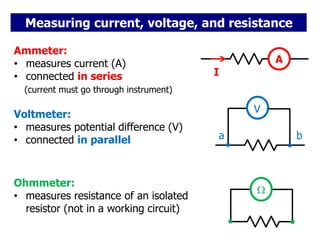
- 1. Measuring current, voltage, and resistance A Ammeter: • measures current (A) • connected in series (current must go through instrument) I V a b Voltmeter: • measures potential difference (V) • connected in parallel Ohmmeter: • measures resistance of an isolated resistor (not in a working circuit)
- 2. Effect of ammeter on circuit V R Measuring current in a simple circuit: A • connect ammeter in series Are we measuring the correct current? (the current in the circuit without ammeter)
- 3. • current without the ammeter would be V R . V I = R Measuring current in a simple circuit: . V I = R +r To minimize error, ammeter resistance r must be very small. (ideal ammeter would have zero resistance) • any ammeter has some resistance r. r • connect ammeter in series Are we measuring the correct current? (the current in the circuit without ammeter) • current in presence of ammeter is Effect of ammeter on circuit
- 4. Example: an ammeter of resistance 10 m is used to measure the current through a 10 resistor in series with a 3 V battery that has an internal resistance of 0.5 . What is the relative (percent) error caused by the ammeter? V=3 V R=10 r=0.5 Actual current without ammeter: V I = R +r 3 I = A 10+0.5 I=0.2857 A =285.7 mA You might see the symbol used instead of V.
- 5. V=3 V R=10 r=0.5 Current with ammeter: A V I = R +r+R 3 I = A 10+0.5+0.01 I=0.2854 A =285.4 mA RA 0.2857-0.2854 % Error = 100 0.2857 %Error =0.1%
- 6. Designing an ammeter http://hyperphysics.phy-astr.gsu.edu/hbase/magnetic/galvan.html#c1 Galvanometer: • current flows through a coil in a magnetic field • coil experiences a torque, connected needle deflects (see later chapters of this class)
- 7. Designing an ammeter • ammeter can be based on galvanometer (for electronic instrument, use electronic sensor instead, analysis still applies) • simplest case: send current directly through galvanometer, observe deflection of needle Needle deflection is proportional to current. Each galvanometer has a certain maximum current corresponding to full needle deflection. What if you need to measure a larger current? • use shunt resistor
- 8. Ammeter uses a galvanometer and a shunt, connected in parallel: A I Everything inside the green box is the ammeter. • Current I gets split into Ishunt and IG G RG RSHUNT IG ISHUNT I A B galvanometer
- 9. G RG RSHUNT IG ISHUNT I A B Shunt also reduces resistance of the ammeter: A G SHUNT 1 1 1 R R R G SHUNT A G SHUNT R R R R R
- 10. Web links: ammeter design, ammeter impact on circuit, clamp-on ammeter (based on principles we will soon be studying).
- 11. Effect of voltmeter on circuit Measuring voltage (potential difference) Vab in a simple circuit: • connect voltmeter in parallel Are we measuring the correct voltage? (the voltage in the circuit without voltmeter) =3 V R=10 r=0.5 V a b
- 12. • extra current changes voltage drop across r and thus Vab To minimize error, voltmeter resistance r must be very large. (ideal voltmeter would have infinite resistance) • voltmeter has some resistance RV • current IV flows through voltmeter Effect of voltmeter on circuit Measuring voltage (potential difference) Vab in a simple circuit: • connect voltmeter in parallel Are we measuring the correct voltage? (the voltage in the circuit without voltmeter) =3 V R=10 r=0.5 RV a b IV
- 13. • voltmeter must have a very large resistance • voltmeter can be made from galvanometer in series with a large resistance V G RG RSer Everything inside the blue box is the voltmeter. a b Vab a b Vab Homework hints: “the galvanometer reads 1A full scale” would mean a current of IG=1A would produce a full-scale deflection of the galvanometer needle. If you want the voltmeter shown to read 10V full scale, then the selected RSer must result in IG=1A when Vab=10V. Homework hints: “the galvanometer reads 1A full scale” would mean a current of IG=1A would produce a full-scale deflection of the galvanometer needle. If you want the voltmeter shown to read 10V full scale, then the selected RSer must result in IG=1A when Vab=10V. Designing a voltmeter
- 14. • Ohmmeter measures resistance of isolated resistor • Ohmmeter can be made from a galvanometer, a series resistance, and a battery (active device). G RG RSer R=? • Terminals of ohmmeter are connected to unknown resistor • battery causes current to flow and galvanometer to deflect • V=I (Rser + RG + R) solve for unknown R Measuring Instruments: Ohmmeter Everything inside the blue box is the ohmmeter. V
- 15. Alternatively: • separately measure current and voltage for resistor • Apply Ohm’s law Four-point probe: V A reference: http://hyperphysics.phy-astr.gsu.edu/hbase/magnetic/movcoil.html#c4