Rotary Gas Meters for Industrial and Commercial Applications
•
1 like•692 views

Rotary displacement gas meters can be employed across a wide range of applications, from residental through commercial and industrial. Their simple design provides predictable accuracy and long term durability.

Recommended
Recommended
More Related Content
More from Classic Controls, Inc.
More from Classic Controls, Inc. (20)
Recently uploaded
Recently uploaded (20)
Rotary Gas Meters for Industrial and Commercial Applications
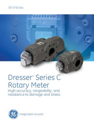
- 1. GE Oil & Gas Dresser* Series C Rotary Meter High accuracy, rangeability, and resistance to damage and stress
- 2. 2 Natural gas companies worldwide use GE’s Dresser rotary meters in commercial and industrial natural gas measurement applications. Our rotary meters are also used in both high flow residential applications and low volume transmission applications. Dresser Series C rotary meters are used at the well head gathering line, compressor stations, gas distribution systems, and end users such as chemical and processing plants. Meters of standard construction are used in the measurement of a variety of filtered and dry non-corrosive gases, including specialty gases. Positive Displacement Operating Principle Dresser rotary meters are designed to measure the volume of gases and gas mixtures with a high degree of accuracy. The rotary type positive displacement operating principle assures permanent, non-adjustable accuracy by using two precision machined dual-lobed impellers encased within a rigid measuring chamber. Unlike other meter types, measurement accuracy is not affected by changes in gas specific gravity, pressure, or fluctuating flow. Dresser rotary meters may be used from atmospheric pressure to 16 bar with highly accurate measurement over a wide operating range. Series C Rotary Meter Design Features ■ Compact size and lower weight ■ High performance rotor (impeller) profile for increased rangeability ■ Superior strength ensures reduced sensitivity to pipe stress ■ Decreased susceptibility to damage from pressure shocks ■ Simplified maintenance and repair ■ Multi-functional index Utilizing advancements in technology and materials, GE Oil & Gas’ innovative Dresser Series C Rotary Meter helps reduce installation and maintenance costs while improving measurement accuracy As shown in the picture, two contra-rotating impellers of two-lobe or “figure 8” design are encased within a rigid measuring chamber, with the inlet and outlet connections on opposite sides. Precision machined timing gears keep the impellers in correct relative position. Optimal operating clearances between the impellers, cylinder and headplates provide a continuous, non-contacting seal.
- 3. 3 Compact Size The compact and space saving Dresser Series C rotary meter is ideal for mounting in small meter stations or cabinets. Rotors The precision machined, high performance rotors are held in place with four main shaft bearings placed outside of the timing gears. This bearing placement strengthens the connection between the rotors and the timing gears. The sophisticated square profile impellers improve not only the accuracy, but also the rangeability of the meter by minimizing leakage between rotors and the body. This design also reduces the deflection of the rotor’s main shafts at high flow rate and elevated pressure where dynamic loading is most prevalent. This feature makes the meter less vulnerable to damage during start up and operation. Rugged Design The Dresser Series C rotary meter’s rugged design is less sensitive to stress from misaligned pipe or flanged connec- tions. Our compact meter body, thick flange connections, and stainless steel bearing support rings facilitate easy installation, and robust performance in the most demanding installations. The square rotors with rigid main shafts are also less susceptible to damage from rapid pressurization of the meter. Low Maintenance / Easy Repair Repair technicians can replace all major parts without special tools. This innovative Dresser measurement cartridge simplifies most main- tenance and repair activities. Technicians can remove the complete measurement mechanism (rotors, timing gears, and bearings) from the meter body in one piece. Whether you just clean the cartridge and re-install it, or replace the cartridge, major repairs are fast and easy. When regulations permit, users can also install a new prover-certified cartridge. Multi Functional Index Dresser Series C rotary meters utilize a magnetically coupled index. A “drive” magnet couples to the “follower” magnet of the index, which in turn drives the odometer on the meter index. The index can be removed or installed with just “one twist and a click”. The magnetic coupling allows for orienta- tion or exchange without decommissioning the meter. A single index is adaptable to all Series C meter sizes due to the gear reduction internal to the meter body. The gear reduction is used to turn the drive magnet at an output ratio common to all Series C meters. By using a common index, the design enables standardization, reduces inventory and maximizes modular flexibility. The Series C index also contains a pocket that can hold different types of Low Frequency (LF) pulse devices, such as reed switches, Wiegand sensors, or fraud detection/tamper indication devices.
- 4. 4 Twin Impeller Design Reduces Downstream Pulsation and Noise The figure-8 lobed impeller rotary meter design inherently creates pulsations as gas flows through the measurement chamber. This is a common and typical phenomenon with rotary meters. Resonance may affect the linearity of the calibration curve. The effect of such pulsa- tions increases with pressure and the resultant resonance may affect components such as pressure regulators within the metering station. Harmonics, or the shift in frequency created by pulsations, can limit the achievable Qmax as the pressure in the measuring chamber varies. Time ActualFlow 14% Time ActualFlow <2% Harmonics is simply a column of air being resonated at its fundamental or lowest frequency. The small pulsation produced by the rotary meter occurs as the flow media quickly changes pressure as the measuring element (impellers) rotate. The amplitude of the pulsation from the measurement cavity is directly proportional to the pressure drop across the meter and the speed of the rotating device. These resonance flow points tend to show up as a higher than expected nominal value on the performance curve. The Twin impeller principle, offered in the larger rotary meter sizes, divides the flow into two measuring chambers. The phase of each pair of impellers is shifted 45 degrees (180 degrees in terms of the sine wave) so that the pulsations are opposing and negligible, or eliminated. Dresser Twin rotary meters provide significantly improved accuracy over conventional rangeability make them ideal choices for reference or master meter applications. Reduced pulsations also significantly reduce ambient noise, making Twin rotary meters ideal for sound sensitive applications. For applications requiring serial communication, the Series C index is available with an encoder. The encoder uses three optical sensors to detect light passing through a specially designed slotted disc rotating within the index. The light detected passing through the disc is converted to a numeric value using Gray Code. The system offers high resolution and allows for instant flow calculation. The Series C index uses an 8 digit odometer and provides direct readings in cubic meters or cubic feet. The index is 100% sealed and is IP 65/IP 55 approved. Also, all Series C electronic devices are ATEX 94/9/EC approved.
- 5. 5 The Advantages of the Series C Meter ■ High accuracy and large rangeability (Qmax/Qmin ratio) ■ Lighter weight - aluminum body ■ Smaller overall dimensions, allowing compact metering stations ■ Low pressure drop ■ Low maintenance - lower Total Cost of Ownership (TCO) ■ Reduced sensitivity to installation stresses - robust meter body ■ Rigid design - reduced vulnerability to overloading and pressure shocks ■ No requirements for minimum inlet and outlet piping runs ■ Easy to view, single oil sight gauge ■ Complies with the requirements of EN, OIML, ISO, PTB, EEC, DVGW and other international and national regulations and guidelines in different countries Technical Data Applications Media: Clean and dry natural gas, town gas, propane, inert gases Industry: Commercial and Industrial gas supply, heating manufacturers, chemical industry Nominal pressure ratings ■ ANSI 150 and PN 10/16 Nominal diameters DN 40 – DN 150 (1-1⁄2”up to 6”) Measuring range From 1:30 to 1:160 (EN 12480) Flow rates 0,5 m3 /h up to 1000 m3 /h Repeatability 0,1 % Measuring accuracy 0,2 Q max to Q max : ± 1 % or better Q min to 0,2 Q max : ± 2 % or better Temperature range Standard: -25°C to +55°C, Material ■ Hard Coat, Anodized Aluminium Alloy Body and Rotors ■ High Grade Steel Alloy Shafts and Timing Gears ■ Ductile Iron Approvals The Dresser Series C meter is designed in accordance with harmonized standards (e.g., EN 12480 and OIML draft R137-1), normative documents (e.g., OIML R32). Type approvals and initial verification include MID CE-085 Directive 2004/22/EC and PED Directive 97/23/EC by conformity testing bodies such as NMi and PTB. Intrinsic Safety certified in accordance with IEC 60079-0, IEC 60079-11 and IEC 60079-26. Our facility is ISO 9001 certified by Lloyd’s Register and quality system approved to Directives 90/384/EEC and 93/68/EEC. Verification and Calibration Dresser Series C meters are each supplied with a calibration certificate. The initial verification and calibration are carried out at the GE Energy factory on an NMi and/or PTB approved calibration bench. As an option, Twin-Impeller rotary meters can be provided with a high pressure calibration from a certified test facility.
- 6. 6 Oil level sight gaugeInstallation ■ The Dresser Series C design permits very compact M&R stations without sacrificing the meter’s accuracy ■ All Series C meters are designed for outdoor installation. The Index is IP 65 approved ■ Gas pipes must be clean and free from foreign impurities such as sand, dirt, welding debris and other particles, as well as liquid ■ Generally it is recommended that a gas filter be installed upstream of the rotary meter, with a 160 μ filtration size ■ Check the flow direction of the meter against the required installation. Preferably, horizontal flow is left to right and vertical flow is top inlet, bottom outlet Standard Features The connector on the standard mechanical index is fitted for two LF outputs and one tamper contact. An HF output is available upon request. The meters are also fitted with a number of pressure and temperature measur- ing connections at the inlet and outlet, suitable for easy connection of electronic gas volume conver- sion devices such as the Dresser Micro Corrector and for ease in differential monitoring. meter index P&T Ports The Dresser Series C meter has been designed for rigorous natural gas measurement applications and able to withstand typical starting up operations with- out degradation of performance or quality. However, to ensure an extended lifetime, care must be given while pressurizing the meter to prevent excessive over-speeding and damaging the rotating parts. A single oil level indicator (sight gauge) is located directly below the index. The oil reservoir should be filled after the meter has been installed. A bottle with sufficient lubrication oil for the initial filling is supplied with every meter. The oil reservoir should be filled until the oil level reaches the middle of the sight glass. Meter with external bypass option. In the unlikely event of a flow blockage, gas supply is guaranteed. An electrical contact can be wired to activate an alarm.
- 7. 7 G-Rating Comparable USA Rating Q-max Rated Capacity (m3 /h) Rangeability 2 x Low Frequency Pulses (pulses/m3 ) G 10 8C 16 1:30 10 G 16 8C 25 1:50 10 G 25 15C 40 1:80 10 G 40 2M 65 1:100 10 G 65 3M 100 1:160 10 G 100 5M 160 1:160 1 G 160T 11M 250 1:160 1 G 160 11M 250 1:160 1 G 250 16M 400 1:160 1 G 400T - 4” 23M 650 1:160 1 G 400T - 6” 23M 650 1:160 1 G 650T 38M 1000 1:160 1 G-Rating Number of Bolts Flange Size Overall Flange to Flange Dimensions mm Height & Depth Overall Weight in Kg (Approx. Values) inch mm mm mm G 10 N.A.** 1½** 32** 121** 130** 190** 3.5 G 16 N.A** 1½** 32** 121** 130** 190** 3.5 G 25 N.A** 1½** 32** 121** 130** 210** 4 G16 4 1½ or 2 40 or 50 171 180 280 10 G25 4 1½ or 2 40 or 50 171 180 280 10 G 40 4 1½ & 2 40 & 50 171 180 280 10 G 65 4 2 50 171 180 280 10 G 100 4/8 3 80 171 200 280 13 G 160T 4/8 3 80 171 200 350 21 G 160 4/8 3 80 241 225 315 27 G 250 8 4 100 241 225 400 30 G 400T - 4” 8 4 100 241 225 510 43 G 400T - 6” 8 6 150 241 225 510 50 G 650T 8 6 150 241 285 680 61 Table 2 - Dimensions and Weights Table 1 - Measurement Ranges and Pulse Data Note: GxxxT=Twin sets of rotors ** Gas thread connection
- 8. GEA19570 Series C Rotary Meter Rev. 07.2012 GE Oil & Gas 16240 Port Northwest Dr., Suite 100 Houston, TX 77041 P: 832.590.2303 F: 832.590.2494 7051HS Vasserveld The Netherlands P: +31 (0) 31527 1100 F: +31 (0) 31527 1105 Visit us online at: www.ge.com/energy ©2012 General Electric Company All Rights Reserved *Denotes trademark of General Electric Company