Urban Water Quality Management
•
3 likes•690 views

Urban Water Quality Management - Domenico D'Alessandro Nov 2010

Recommended
More Related Content
More from Matthew Hahm
More from Matthew Hahm (8)
Urban Water Quality Management
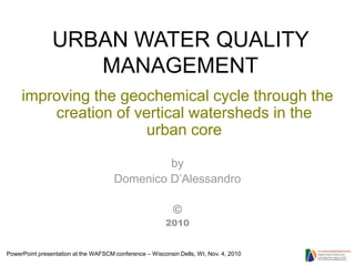
- 1. URBAN WATER QUALITY MANAGEMENT improving the geochemical cycle through the creation of vertical watersheds in the urban core by Domenico D’Alessandro © 2010 PowerPoint presentation at the WAFSCM conference – Wisconsin Dells, WI, Nov. 4, 2010
- 4. Chicago-Milwaukee area - Chicago has been using groundwater since at least 1864 and groundwater has been the sole source of drinking water for about 8.2 million people in the Great Lakes watershed. This long- term pumping has lowered groundwater levels by as much as 900 feet. This map shows contours of water-level declines, in feet, in the Chicago-Milwaukee area from 1864 to 1980. AQUIFER DECLINE MAP IN THE UNITED STATES source:The Water Campws
- 5. ELEVATED MERCURY ORGANIC TOXINS ELEVATED NUTRIENTS PESTICIDES COMBINED WATER PROBLEMS MAP ACID RAIN
- 6. carbon dioxide nitrogen oxide sulfur dioxide CHICAGO 2005 Data heat
- 7. We must define the ecology of the urban core area and treat it accordingly.
- 13. We must be able to create bio-diverse environments in the urban context where traditional methods of restoration ecology cannot be employed.
- 14. Chicago River looking west - 2004 Appending eco-panels to building facades that don’t have significant architectural Future site value of Trump building Direct architectural eco-link to the river Appending eco-structures to Floating platform ecosystem the seawall anchored to seawall
- 15. Chicago River Fish Hotel
- 16. VIEW STATION KIOSK ANCHORING UNITS FLOATING SUPPORT FRAME ISLAND FRAME FISH CRIB
- 17. 2005 2006 Installation as envisioned by Domenico D’Alessandro
- 18. B A PLACE FOR ALL I R D S I N S BIRDS AND E INSECTS R C REPTILES E T P S AND T AMPHIBIANS I L E A S M P H I FISH B I A N S F I S H M O L L MOLLUSKS U S K S
- 19. Vertical habitat creation along river walls will change the overall experience for boaters and paddlers.
- 21. Book and artisans fairs along river walk. The summer booths may be rented for periods at a time. The area above the booths demarcated by the gratings is open to allow airflow for Lower Wacker Drive.
- 26. A living wall system based on the use of tubular structures by cheremserrano arquitectos. Living wall system at Vancouver’s Aquarium, BC, Canada
- 27. Roof runoff is collected into four water storage tanks with a combined capacity of 12,000 gallons.
- 28. Ms •Bulk Density (ρb) ρb = Vb Ms •Particle Density (ρp) ρp = Vs •Porosity (φ) ρb φ = 1 − 100% φ = volume of pores volume of soil ρp Mw –Soil water content θm = Ms •Volumetric water Vw content (θv) θv = Vb soil water potential ψt = ψg + ψm + ψo Fraction available θfc − θv fd = water depleted (fd) θfc − θwp θv − θwp Fraction available fr = water remaining (fr) θfc − θwp
- 29. The sequence of destinations of rainwater (Shaxson, 2001 after FAO, 1995b) 1. Direct evaporation from wetted leaf surfaces. 2. Surface runoff/stormflow. 3. Direct evaporation from the soil surface. 4, 5, 6. Plant-available soil moisture within root-range of existing weeds, crops, trees. 7. Soil moisture within root-range of existing plants but held at tensions unavailable to them. 8. Soil moistures held at all tensions, but below root-depth of existing plants. 9. Water not captured by roots and small pores, moving to groundwater and streamflow. 10. Leakage to deep groundwater beneath catchment floor
- 32. Bio- Shaft Concept Green roof is pitched so the access water will flow into the bio-shaft. The bio-shaft comprises of a column of soil that allows for the establishment of a viable geochemical cycle. It may be designed to have a Bio-panels on façade variety of soil stratification of building provide and include perched water food and shelter for tables if desired. migratory birds. Interior green walls are fed by the bio-shaft. The Biofiltration of air roots of the plants provide a suitable environment for Ledge drains collect microbiological activity. the access water from The plants help purify the the eco-panels and the air and create a healthier water that slides down working environment. the façade during rain events and channel it into the bio-shaft. The interior walls may The filtered water is be a combination of captured in a cistern an plants, sculpture and recycled throughout the light shafts. building where needed.
- 33. •engineered vertical recharge system •above ground geochemical cycle •a variety of levels of saturation, and a healthy capillary action •zero runoff and a healthy live water resource •percolation process will not be compromised when infrastructure repair or update work is needed at ground level and will not succumb to all the various debris and chemical pollution of street runoff, in particular salinity from winter road maintenance. •help prevent overflows in already taxed water reclamation systems by extending the flow period •self-cleaning, CO2 absorbing cement •walls fitted with sensors that monitor environmental conditions and makes appropriate adjustments •plumbing system control climate and moisture regimes within the shaft •smaller interconnected components or be a stand alone structure that provides treatment of runoff from surrounding existing buildings. • extend green roof potential for creating habitat niches
- 34. HIGH ELEVATION NATURALIZED POND BUILDING ENVELOPE BIOSHAFT GREEN ROOF BIOSHAFT BUILDING ENVELOPE UTILITIES TUNNEL CONNECTION UNMDERGROUND PARKING DEBRIS HAZARDOUS HIGHLY PLUMES COMPACTED SUBSTRATE SUBWAY
- 35. GREEN ROOF AS A COHESIVE SUSTAINABLE HABITAT DESIGN FROM THE SKETCHBOOK OF DOMENICO D’ALESSANDRO
- 36. Filtration Tower Desalination stage of runoff water- inner core Filtration of leachate in middle core Planted areas in double-helix wings Tower composed of prefabricated units.
- 37. Plant material selected to handle the leachate from the core and further neutralize the water before it is released into the adjoining landscape.
- 42. MILWAUKEE