EEG Acquisition Device to Control Wheelchair Using Thoughts

With the advancements in technology and health-care facilities, the number of senior citizens has increased and thus the number of elderly who find it difficult to walk. Hence there is a need for designing a wheelchair that is user friendly and involves fewer complexities. In this context, we propose a thought controlled wheelchair, which uses the captured signals from the brain and process it to control the wheelchair. This wheelchair can also be used by the physically challenged who depend on others for locomotion. Rehabilitation centers at hospitals can also make use of this wheelchair. In this paper, we explain the design and analysis of the thought-controlled wheelchair. In addition, we present some of the experiments that were carried out and the corresponding results in this paper. http://www.vivek-chan.in

Recommended
Recommended
More Related Content
What's hot
What's hot (20)
Viewers also liked
Similar to EEG Acquisition Device to Control Wheelchair Using Thoughts
Similar to EEG Acquisition Device to Control Wheelchair Using Thoughts (20)
More from Vivek chan
More from Vivek chan (20)
Recently uploaded
Recently uploaded (20)
EEG Acquisition Device to Control Wheelchair Using Thoughts
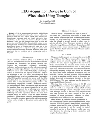
- 1. I. INTRODUCTION II.PROBLEM STATEMENT BRAIN Computer Interface (BCI) is a technique that provides direct interface between the human brain and the computer. BCI techniques are broadly classified into invasive and non-invasive techniques. Non-invasive techniques are becoming more popular and more research is being done on this topic. There are various non-invasive BCI techniques such as EEG, Electro-Oculography. EEG technique deploys an electrode cap that is placed on the user’s scalp for the acquisition of the EEG signal, which relates the scalp potential differences to various complex actions. Classification of the EEG signal has been made into several bands like alpha, beta, delta, theta and mu suppression, each corresponding to various states of being like relaxing, ranging over 8-14 Hz; concentrating, ranging over 13-30 Hz; deep sleep, from 0-4 Hz; meditating from 4-8 Hz; moving your hands or legs or just by imagining these motor actions respectively. As it is being non-invasive in nature, it has an advantage over traditional BMI, not being hazardous to health. With the advent of technology the EEG acquisition devices are made more compact, handy and wireless. Using the above mentioned technique, a simple thought controlled wheelchair system has been proposed in this paper. A section that briefly explains the various blocks included in the system is also added in this paper. III. Concept The study focus on the target selection of BCI 2D cursor using hybrid feature. As in most of the applications, 2D cursor control is used as a sequential control, which involves cursor control and target selection. The paper focuses on the latter, the target selection of the cursor using a hybrid feature from P300 potential and motor imagery. It has got an advantage of better performance compared to others, especially in case of subjects with poor performance. Paper proposes a wheelchair control methodology in which the motion of the chair is controlled based on the inputs from user (P300 brain signals), data obtained from obstacle avoidance sensors and by using localization algorithm. The brain signal processing is not fast enough to control wheelchair in real time so these signals are used to make long term decisions like choosing a distant destinations and complex obstacle avoidance. By: Vivek Chan 2012 Vivek_chan@live.com EEG Acquisition Device to Control Wheelchair Using Thoughts Abstract— With the advancements in technology and health-care facilities, the number of senior citizens has increased and thus the number of elderly who find it difficult to walk. Hence there is a need for designing a wheelchair that is user friendly and involves fewer complexities. In this context, we propose a thought controlled wheelchair, which uses the captured signals from the brain and process it to control the wheelchair. This wheelchair can also be used by the physically challenged who depend on others for locomotion. Rehabilitation centers at hospitals can also make use of this wheelchair. In this paper, we explain the design and analysis of the thought-controlled wheelchair. In addition, we present some of the experiments that were carried out and the corresponding results in this paper. The paper cited in presents how to control a cursor in 2D using EEG based BCI. The movements of the cursor on the computer screen are controlled based on the EEG scalp potentials. The EEG signal is mapped from the user head to the 2D cursor control. The horizontal motion is based on the mu beta rhythm and vertical motion is based on P300 potential respectively. The user can move the cursor horizontally to the right just by imagining his right hand motion and the same way the left hand motion imagination is mapped to move the cursor left. The user can move the cursor vertically upwards by focusing on one of the three UP buttons on the monitor and similarly downwards by focusing on the either of the three DOWN buttons. This same technique can be deployed in designing a BCI based wheelchair. There are nearly 7 billion people our world as in out of which there are a considerably large number of people who has at least one affliction. One of the most distressing one that anybody can have is paralysis of body parts. Paralysis can make the affected to seriously depend on others even for activities of daily living. This paper intends to unfold a solution for this problem. A wheelchair is designed using BCI technique so that a person with any extent of disability can operate the wheel chair to attain self-independence at least in activities of daily life.
- 2. IV. WHEELCHAIR SYSTEM DESIGN Fig.1Block Diagram of the Wheelchair System The system is broadly divided into four blocks, thought acquisition block, thought transmission block and thought processing block and motor control block each of which aims at acquisition of the EEG signal from user scalp and processing it for controlling a wheelchair. EEG scalp potentials obtained are amplified, digitized and transmitted to a processor and after processing the output of the processed signals are used to control the wheelchair. The four main blocks involved in the wheelchair system are briefly discussed below. A.Thought Acquisition Block filters. The high pass filter, removes the noise in the signal. Low pass filter extracts the signal frequencies of interest. As DC power supplies are used, one common problem to encounter is the 60 Hz power line signal. This 60 Hz power line signal will distort the EEG scalp potentials. Integration of a notch filter will filter out this undesirable power line signal. This block has been simulated and its details is been explained in the later sections of this paper. One of the disadvantages that can be considered about this system is that users with Slow Cortical Potentials (SCPs) cannot use this system. SCP is a state where the motor reflex of the patient is very slow and hence there is a delay between the mechanical input to the system and thereby a delay in the response of the system. Fig.3 Schematic Outlining various stages involved in thought acquisition block B.Thought Transmission block This block focuses on the transmission of the acquired EEG signal (thought) to a processor. It consists of 12-bit A/D converter for digitizing the EEG signal. The ATMega644 microcontroller is used for UART transmission. This microcontroller is having a 10-bit A/D converter peripheral, which cannot be used because of lesser resolutions. That is the reason we are using an external 12-bit A/D converter. The FTDI USB RS232 is an opto-coupler used for electrical isolation to prevent electrical hazards during the transmission of the digitized EEG signal to a DSP as shown in Fig.3. It is also used for converting the RS232 signals to USB signals so that this setup can be interfaced to a processor. Fig.4 Schematic outlining various stages involved in thought transmission block C.Thought Processing Block This block consists of processor which processes the signal that is transmitted from the thought acquisition block to processor through the thought transmission block. Electrodes non-invasively placed on head Thought capture and Identification Module Interfacing circuitry Amplification, Filtering, Digitizing Signal Processing Unit (Microprocessor) Microcontroller for Generating PWM and Direction signals Motor controller Module PMDC LEFT MOTOR PMDC RIGHT MOTOR This block primarily targets at the careful extraction of the EEG signal from the user scalp. It is made up of different blocks such as instrumentation amplifier, operational amplifier, high pass, low pass and notch filters. The purpose of the instrumentation amplifier is to extract the EEG signal. The extracted EEG signal is passed through the operational amplifier block for proper amplification, It is then, passed through the high pass, low pass and notch
- 3. D.Wheelchair Control System The wheelchair controller has the functionality of controlling the direction and speed of the wheelchair based on the output bits obtained from the signal processing block. Hercules motor driver is used in between the Arduino and the Permanent Magnet Direct Current (PMDC) motors. This module is used to control the motors in real time wheelchair. Two motors connected to the rear wheels of the wheelchair have to be controlled to define its motion. The PMDC motors can be controlled using Pulse Width Modulation (PWM) techniques that can be generated using the Arduino Board. The power wheelchair can be directionally controlled using suitable motor driver. Super Hercules 9V – 24V, 15A motor drivers are used to control the motors. These motor drivers can take up to 30A peak current load and can be operated up to 10 KHz PWM. The direction of the movement can be controlled using a separate pin on the motor driver which is used as direction pin. Hence the wheelchair can also be made to move in the reverse direction with the help of the direction pin on the motor controller. The control signals which include PWM and direction signals are given by Arduino board to Hercules motor driver. The motor driver acts as a switch between the input 5V signal and required 24V output signals. The wheelchair moves at considerably good speed when it is given 15 volts. So to avoid jerk or a sudden unwanted vibration when the wheel chair starts or stops or changes direction, the PWM signal is incremented or decremented according to the needs in linear steps rather that a sudden transition. V.THOUGHT PROCESSOR-WHEELCHAIR CONTROL SYSTEM INTERFACE The thought processing block detects the brain signals for focusing eye to the left, right, up or down and uses it to calculate a cursor location (co-ordinate of a point) by using the algorithm in [2]. This coordinate is the used to finds out the difference between newly calculated cursor location and present cursor location. The difference in the coordinate values of these locations is then used to find the angle between the line joining newly calculated location and present location with x axis as reference axis. The thought processing block outputs 3 bits of data, out of which bit 1 is set if the calculated change in abscissa and ordinate are both zero (indicative of stop gesture).If one the change in value is non-zero then bit 1 is cleared and the calculated angle is used to find the other two bits as explained in Fig. 3. The 3 bits of data which defines the identified gesture are shown in table 1. VI. EXPERIMENT The simulation of the EEG amplifier used in thought acquisition module is done using Multisim Simulation tool. The EEG Amplifier, shown in Fig.6 is designed based on the circuit shown in [1]. It consists of an instrumentation amplifier, operational amplifier and a voltage follower with a virtual ground set up. The gain of instrumentation amplifier is given by G = (49.4kohm/Rg) + 1. It is calibrated to have a gain of about 23 (using Rg = R1). Fig.5 Diagrammatic representation of calculated angle and corresponding gesture TABLE I THE OUTPUT OF THOUGHT PROCESSING BLOCK SL NO. IDENTIFIED GESTURE BIT 1 BIT 1 BIT 3 1 Stop 0 X X The gain of the operational amplifier, used for post amplification purpose, is given by (-R2/R1). It is designed to have a gain of around 65 (using appropriate R2 and R3). Thus the overall circuit gain is about 1500, approximately. Two First Order high pass filters are integrated; one each after instrumentation amplifier and operational Amplifier (OP- AMP). A first order low pass filter is integrated along with the operational amplifier. We have used AD620 as an instrumentation amplifier; it is used for pre amplification purpose, with a nominal gain of about 23. This stage of amplification is mainly aimed at the EEG signal extraction, whose value ranges in micro volts, without being distorted. The instrumentation amplifier provides high input impedance to the EEG electrodes. The idea behind infinite input impedance is to assure zero attenuation of EEG signal across electrodes. The voltage follower along with a virtual ground set up with CA3140 collectively known as virtual ground. Virtual ground is coupled with the instrumentation amplifier to provide a DC offset. Virtual grounds are used to cope up with the problem of dual power supplies. The DC offset provided by the virtual ground to the pre amplification stage is treated as the reference with respect to which the single power supply is seen as a dual power supply. 2 Left 1 0 0 3 Right 1 0 1 4 Forward 1 1 0 5 Backward 1 0 0
- 4. Fig.6.Schematic of the circuit simulated in the Multisim. CA3140 is used as an OP-AMP, for post amplification purposes, with an approximate gain of around 65. This stage of amplification is aimed at maximum gain.A high pass filter is coupled in between pre and post amplification stages and another is coupled after post amplification stage, both with a cut-off 0.13 Hz. Each of these high pass filters prevents the low frequency noise being carried to the later stage. EEG signals of interest range to a maximum of 48 Hz. A low pass filter with a bandwidth of 48 Hz is integrated along with the OP-AMP to extract the frequencies of interest. The next part of the simulation involves the Proteus simulation tool for building and testing the microcontroller Part of the system as show in Fig. 3. The circuit shown in the Fig.8 is the simulation schematics of the microcontroller for ADC conversion and UART transmission. ATmega644 microcontroller used. It is an 8-bit Atmel Microcontroller with 64K Bytes in-System Programmable Flash and 10-bit ADC. For simulation purpose, we have used the internal A/D peripheral block instead of an external 12-bit ADC. The input sine wave is given through analog pin A1 and expected output is taken through digital pin D1. The digital output is verified through the Oscilloscope, which is connected to the microcontroller as shown in the Fig.6. VII. RESULT The bode plots of the amplifier setup are shown in Fig 8a and 8b. These plots show the frequency response of the circuit in Fig.6, with its lower cut-off, 4Hz and upper cut-off, 48Hz. Frequencies in between lower and upper cut-off refer to the pass band of the amplifier. Fig.7 Schematic of the circuit simulated for UART transmssion Frequencies outside the pass band got a gain less than one third of the maximum gain, 1500, of the amplifier. A maximum gain of about 1500 is observed for central frequencies of the pass band. Fig. 8a shows the plot without the notch filter. The small lobe on the right side of the bode plot in Fig. 8b, refers to the 60Hz notch of the notch filter. The waveforms (1) and (2) shown in Fig.9a are the input and output waveforms of the first stage of amplification in the circuit shown earlier in Fig. 6.For an input signal (1) of a frequency well within the pass band of the amplifier, the output signal after first stage of amplification is observed to have a gain of about 23. This output waveform is observed with a dc offset of 2.5 volts. The (3) and (4) output waveforms shown in Fig. 7b are the input and output waveforms of the post amplification stage of the same circuit. U1 AD620AN 3 2 6 7 1 8 54 R1 2.2kΩ VCC 5V VCC 5V VCC 5V VCC 5V VCC 5V C1 1uF U2 CA3140E 3 2 4 7 6 51 8 R3 1MΩ 1MΩ Key=A 50% R6 1MΩ R7 10kΩ C3 440nF R2 2.2kΩ U3 CA3140E 3 2 4 7 6 51 8 R4 15kΩ R8 15kΩ R9 1MΩ VCC VCC 10 VCC6 VCC 2 1 VCC 0 C2 6.8nF V1 30mVrms 60 Hz 0° 0 3 11 13 12 4 R10 9.8MΩ R11 9.8MΩ R12 4.9MΩ C4 270pF C5 270pF C6 540pF R13 50kΩ Key=A 50% VCC 5V VCC 5V U4 CA3130E 3 2 4 7 6 51 8 U5 CA3130E 3 2 4 7 6 51 8 0 14 17 VCC VCC 16 0 7 18 15 0 9 8
- 5. Fig.8a Frequency response of the amplifier, without notch filter Fig.8b Frequency response of the amplifier, with the notch filter Fig.9a Output waveform after first stage of amplification Fig.9b Output waveform after second stage of amplification For the input waveform (3) within the pass band frequency along with a DC offset, the post amplification stage is observed to have a gain of around 65. Fig.10 Output waveform of the UART transmission REFERENCES [1] http://people.ece.cornell.edu/land/courses.ece4760/FinalProjects/ s2012/cwm55/cwm55mj294/index.html [2] Yuanqing Li, Chuanchu Wang, Haihong Zhang and Cuntai Guan, “An EEG-based BCI System for 2D Cursor Control,” IEEE International Joint Conference on Neural Networks, 2008. [3] Jinyi Long, Yuanqing Li*, Tianyou Yu, and Zhenghui Gu, “Target Selection With Hybrid Feature for BCI-Based 2-D Cursor Control,” IEEE Trans. Biomedical Engineering. January 2012. [4] Brice Rebsamen, Chee Leong Teo, Qiang Zeng, and Marcelo H.Ang Jr., Etienne Burdet, Cuntai Guan and Haihong Zhang, Christian Laugier, “Controlling a wheelchair indoors using thought,” published by IEEE Computer Society 2007. [5] www.atmel.com/Images/doc2593.pdf - United States [6] http://www.100people.org/statistics_100stats.php?section=statistic