Thermon RSX 15-2 Heat Tracing Cable - Spec Sheet
•
0 likes•1,488 views

Thermon RSX 15-2 Heat Tracing Cable

Recommended
Recommended
More Related Content
What's hot
What's hot (20)
Viewers also liked
Similar to Thermon RSX 15-2 Heat Tracing Cable - Spec Sheet
Similar to Thermon RSX 15-2 Heat Tracing Cable - Spec Sheet (20)
More from Thorne & Derrick UK
More from Thorne & Derrick UK (20)
Recently uploaded
Recently uploaded (20)
Thermon RSX 15-2 Heat Tracing Cable - Spec Sheet
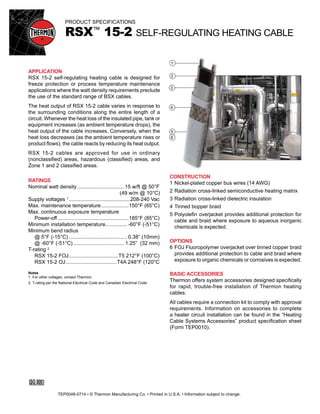
- 1. PRODUCT SPECIFICATIONS RSX™ 15-2 SELF-REGULATING HEATING CABLE CONSTRUCTION 1 Nickel-plated copper bus wires (14 AWG) 2 Radiation cross-linked semiconductive heating matrix 3 Radiation cross-linked dielectric insulation 4 Tinned bopper braid 5 Polyolefin overjacket provides additional protection for cable and braid where exposure to aqueous inorganic chemicals is expected. OPTIONS 6 FOJ Fluoropolymer overjacket over tinned copper braid provides additional protection to cable and braid where exposure to organic chemicals or corrosives is expected. BASIC ACCESSORIES Thermon offers system accessories designed specifically for rapid, trouble-free installation of Thermon heating cables. All cables require a connection kit to comply with approval requirements. Information on accessories to complete a heater circuit installation can be found in the “Heating Cable Systems Accessories” product specification sheet (Form TEP0010). APPLICATION RSX 15-2 self-regulating heating cable is designed for freeze protection or process temperature maintenance applications where the watt density requirements preclude the use of the standard range of BSX cables. The heat output of RSX 15-2 cable varies in response to the surrounding conditions along the entire length of a circuit. Whenever the heat loss of the insulated pipe, tank or equipment increases (as ambient temperature drops), the heat output of the cable increases. Conversely, when the heat loss decreases (as the ambient temperature rises or product flows), the cable reacts by reducing its heat output. RSX 15-2 cables are approved for use in ordinary (nonclassified) areas, hazardous (classified) areas, and Zone 1 and 2 classified areas. RATINGS Nominal watt density................................. 15 w/ft @ 50°F (49 w/m @ 10°C) Supply voltages 1...........................................208-240 Vac Max. maintenance temperature....................150°F (65°C) Max. continuous exposure temperature Power-off..................................................185°F (85°C) Minimum installation temperature............... -60°F (-51°C) Minimum bend radius @ 5°F (-15°C)......................................... 0.38” (10mm) @ -60°F (-51°C).................................... 1.25” (32 mm) T-rating 2 RSX 15-2 FOJ...................................T5 212°F (100°C) RSX 15-2 OJ....................................T4A 248°F (120°C Notes 1 . For other voltages, contact Thermon. 2. T-rating per the National Electrical Code and Canadian Electrical Code. 1 2 3 4 5 6 Tel: +44 (0)191 490 1547 Fax: +44 (0)191 477 5371 Email: northernsales@thorneandderrick.co.uk Website: www.heattracing.co.uk www.thorneanderrick.co.uk TEP0048-0714 • © Thermon Manufacturing Co. • Printed in U.S.A. • Information subject to change.
- 2. PRODUCT SPECIFICATIONS RSX™ 15-2 SELF-REGULATING HEATING CABLE POWER OUTPUT CURVES 1 The power outputs shown apply to cable installed on insulated metallic pipe (using the procedures outlined in IEEE 515) at the service voltages stated below. For use on other service voltages, contact Thermon. CIRCUIT BREAKER SIZING 2 Maximum circuit lengths for various circuit breaker amperages are shown below. Breaker sizing should be based on the National Electrical Code, Canadian Electrical Code or any other applicable code. The National Electrical Code and Canadian Electrical Code require ground-fault protection of equipment for each branch circuit supplying electric heating equipment. Check local codes for ground-fault protection requirements. 240 Vac Service Voltage Max. Circuit Length 3 vs. Breaker Size ft (m)) Catalog Number Start-Up Temperature °F (°C) 20A 30a 40a RSX 15-2 50 (10) 205 (63) 320 (98) 380 (116) 0 (-18) 145 (45) 225 (70) 315 (97) -20 (-29) 130 (40) 200 (62) 280 (86) -40 (-40) 120 (36) 180 (55) 250 (77) Catalog Number 240 Vac Nominal Power Output at 50°F (10°C) w/ft (m) RSX 15-2 15 (49) 18 (59) 16 (52) 14 (46) 12 (39) 8 (26) CERTIFICATIONS/APPROVALS FM Approvals Ordinary Locations Hazardous (Classified) Locations Class I, Division 2, Groups B, C and D Class II, Division 2, Groups F and G Class III, Divisions 1 and 2 Class I, Zones 1 and 2, AEx e II (requires FOJ) Underwriters Laboratories Inc. Ordinary Locations Hazardous (Classified) Locations Class I, Division 2, Groups A, B, C and D Class II, Division 2, Groups F and G Class III, Divisions 1 and 2 Canadian Standards Association Ordinary Locations Hazardous (Classified) Locations Class I, Division 1, Groups A, B, C and D Class II, Division 1, Groups E, F and G Class I, Division 2, Groups A, B, C and D Class II, Division 2, Groups E, F and G Ex e II Nominal Watts per Foot (w/m) 10 (33) Pipe Temperature °F (°C) 4 (13) 30 (-1) 50 (10) 70 (21) 90 (32) 110 (43) 130 (54) 150 (66) RSX 15-2 6 (20) Notes 1. For more precise power output values as a function of pipe temperature, refer to CompuTrace®. 2. Based on the trip current characteristic of Type QOB or Type QO equipment protection devices. For devices with other trip current characteristics, contact Thermon. 3. The maximum circuit length is for one continuous length of cable, not the sum of segments of cable. Refer to CompuTrace® design software or contact Thermon for current loading of segments. Tel: +44 (0)191 490 1547 Fax: +44 (0)191 477 5371 Email: northernsales@thorneandderrick.co.uk Website: www.heattracing.co.uk www.thorneanderrick.co.uk