
Recommended
Recommended
More Related Content
Similar to Structural Grid Dimensioning and Documentation for Large Scale Steel Roof Building
Similar to Structural Grid Dimensioning and Documentation for Large Scale Steel Roof Building (20)
Recently uploaded
Recently uploaded (20)
Structural Grid Dimensioning and Documentation for Large Scale Steel Roof Building
- 17. LETTERBOX BY OTHERS - 10 BOXES 4 merino st SIGNAGE PLATE - FULL HEIGHT AND WIDTH STREET ADDRESS SIGNAGE 1 2 3 4 5 6 7 8 9 10 1340 490 PROPRIETARY SCREENING - THE FENCE DEPOT OR APPROVED EQUIVALENT REFER TO SCHEDULE 1500 AUSTRALIA POST GUIDELINES NOMINATE THAT THE ELEVATION OF AN APERTURE ABOVE GROUND LEVEL FOR A GROUP MAIL BOXES MUST BE BETWEEN 600mm AND 1600mm 910 1600 200 SCN-01 4800 2400 2400 SCN-01 RL LEVEL 1 25800 1100 200 BAL-01 PROPRIETARY SCREENING - OXWORKS BALUSTRADE SYSTEM OR APPROVED EQUIVALENT REFER TO SCHEDULE 200MM OVERHANG BELOW THE SLAB LEVEL RL LEVEL 1 25800 1800 SCN-02 200 1460 200 A12.02 9 A12.02 10 A12.02 8 SCN-03 FG D E1.8 A12.02 26 1280 850 400 TYP. 400X200 RENDER BLOCKWORK 6270 400 EQ 400 EQ 400 200 X 400MM BLOCK COLUMN FEN-01 FEN-01 SCN-03 SCN-03 SCN-03 50 GATE 1240 850 200 1500 SCN-03 1500 400 ALUMINIUM BATTEN GATE 400 1500 EQ SCN-03 SCN-03 50 1500 EQ 200 200 6270 400 400 EQ EQ 6270 50 FEN-01 1800 FEN-01 1800 HIGH TIMBER PALLING FENCE TYP. 400X 200 RENDERED BLOCKWORK 1500 RL LEVEL 1 25800 BAL-02 1100 200 VARIES 6 A12.02 CL-01 - JAMES HARDIE STRIA CLADDING hello upper ground 2 1 4 3 6 5 10 9 900 600 LOCATION: MOUNTING HEIGHT TO BE CONFIRMED ON SITE ALUMINIUM POWDERCOATED SIGN WITH CONTRASTING BLACK DIAGRAM AND TEXT MOUNTED TO BLOCKWORK WALL USING PROPRIETARY MASONRY SUITABLE FIXINGS ALL FIXINGS TO BE STAINLESS STEEL 7 8 * FEN-01 1800 75 PROPRIETARY TIMBER PALING FENCE- TIMBER QUEENSLAND OR APPROVED EQUIVALENT REFER TO SCHEDULE RL GROUND LEVEL 22800 PROPRIETARY SCREENING - THE FENCE DEPOT OR APPROVED EQUIVALENT REFER TO SCHEDULE 1800 1500 1100 CL-01 CLADDING PINE RAIL WITH NATURAL STAIN CL-01 CLADDING 150 75MM STUD WALL 30 AWN BAL-01 BAL-02 BD CL-01 CL-02 COL CL DP EG FEN-01 FEN-02 FEN-03 MRS SCN-01 SCN-02 SCN-03 SSH WS AWNING OVER DOOR PROPRIETARY ALUMINIUM BALUSTRADE CL-01 WALL BALUSTRADE PWD SHARED ZONE BOLLARD FC PLANK CLADDING PAINTED FC GABLE END COLUMN REFER TO STRUCTURAL ENGINEER'S DRAWINGS CLOTHES LINE DOWNPIPE EAVES GUTTER PROPRIETARY UNPAINTED TIMBER OVERLAPPED PALING FENCE PROPRIETARY ALUMINIUM POWDERCOATED RAILING FENCE PROPRIETARYALUMINIUM POWDERCOATED RAILING FENCE METAL ROOF SHEETING PROPRIETARY ALUMINIUM POWDERCOATED SCREEN TYPE 1 PROPRIETARY ALUMINIUM POWDERCOATED SCREEN TYPE 1 BIN STORE ALUMINIUM POWDERCOATED SCREEN SHADE/PRIVACY SCREENING TO WINDOWS WHEEL STOPS REFER TO SPECIFICATION AND SCHEDULE EXTERNAL LEGEND 1 : 50 FEN- 02 - POWDERCOATED ALUMINIUM 1 : 50 SCN-01 ALUMINIUM SCREEN 1 : 50 BAL-01 FRAMED ALUMINIUM 1 : 50 SCN - 02 - FRAMED ALUMINIUM SCREEN 1 : 50 BIN STORE FLOOR PLAN REFER 1 : 50 A12.02 BIN STORE ELEVATION 2 8 8 REFER 1 : 50 A12.02 BIN STORE ELEVATION 1 9 9 REFER 1 : 50 A12.02 BIN STORE ELEVATON 3 10 10 FALL FALL FALL FALL 1 : 50 BAL-02 -WALL BALUSTRADE REFER 1 : 20 SIGNAGE DETAIL - WAYFINDING 23 23 1 : 50 FEN - 01- TIMBER PALING FENCE 1 : 50 FEN -03 - POWDERCOATED ALUMINIUM 1 : 50 SCN 03 - FRAMED ALUMINIUM PROPRIETARY BATTEN SYSTEM ULLRICH ULLTRA BATTEN UBEC5050 OR APPROVED EQUIVALENT - ALUMINIUM SCREENING REFER TO SCHEDULE PROPRIETARY BATTEN SYSTEM ULLRICH ULLTRA BATTEN UBEC2550 OR APPROVED EQUIVALENT - ALUMINIUM SCREENING REFER TO SCHEDULE PROPRIETARY BATTEN SYSTEM ULLRICH ULLTRA BATTEN UBEC5050 OR APPROVED EQUIVALENT - ALUMINIUM SCREENING REFER TO SCHEDULE 1 : 50 BAL-02 SECTION
- 18. SHR A13.02 2 1 3 4 SHR 910 900 B01 TRH01 FW HW DR WM L D 7.4 W 7.1 900 500 IW03 DR 150 600 900 2100 FFL CEILING CL02 BENCH 900 1200 CC HOBLESS SHOWER HOBLESS SHOWER TIL-01 SUPPLY AND INSTALL DRYER MOUNT SUPPORT WC01 SH01 EW02 WC01 B01 CL02 TRH 700 TRH01 FRAMELESS TOUGHENED GLASS SHOWER SCREEN CC AS AS SHN MI IW01 IW01 CL02 SUPPLY AND INSTALL DRYER MOUNT SUPPORT CC 150 600 900 2100 FFL CEILING 1200 TIL-01 LT DR WM HW IW01 CL02 CC B01 LT SHR A13.02 8 7 9 10 970 TRH01 900 FW 1:80 FALL HW DR WM WC01 SH01 500 20090 1530 1610 900 IW03 700 FRAMELESS TOUGHENED GLASS SHOWER SCREEN CC CL02 WC01 SH01 IW03 HOBLESS SHOWER AS AS CC CL02 B01 150 600 900 2000 FFL CEILING 1200 SH01 MI B01 HW EW02 EW02 AS AS CC CL02 SUPPLY AND INSTALL BRACKET SUPPORT FOR DRYER B01 HW DR WM 900 IW01 IW01 EW02 DR 150 600 900 2000 FFL CEILING 1200 AS AS CC CL02 TR TRH01 800 TIL-01 EW02 150 1200 900 2100 FFL CEILING WC01 CC B01 SH01 FRAMELESS TOUGHENED GLASS SHOWER SCREEN SH01 EW02 CC SH01 TR WC01 TRH01 TIL-01 IW01 150 900 2100 FFL CEILING CC 800 TR TRH01 WC01 IW01 TIL-01 CC MI B01 B SHR A13.02 11 12 13 14 SHR 900 SHR 900 CLEAR 2030 B01 FW 1:80 FALL TRH01 TR 2050 500 ADJUSTABLE SHELF BASIN WITH MIXER TYPE 1 BASIN WITH MIXER TYPE 2 BENCH TOP CORNICE AS SPECIFIED COAT HOOK COOK TOP DRYER DISH WASHER 600mm GRAB/SHOWER RAIL HOT WATER UNIT KICK BOARD - AS SPECIFIED LAUNDRY TUB MIRROR MICROWAVE OPEN SHELF WALL OVEN RANGE HOOD REFIGERATOR AS B01 B02 BT CC CH CT DR DW GR HW KB LT MI MV OS OV RH REF FIXTURE LEGEND: SHOWER CURTAIN TRACK STRIP/LINEAR DRAIN SHOWER SHOWER AND TAPWARE TYPE 1 SHOWER AND TAPWARE TYPE 2 SHOWER NICHE (350MMX 350MM) SINK COVED SKIRTING - MATCH FLOOR TILES TOILET ROLL HOLDER STANDARD TOILET ROLL HOLDER SEMI RECESSED WATER CLOSET STANDARD WATER CLOSET AMBULANT WASHING MACHINE SCT SDR SHR SH01 SH02 SHN SK ST01 TRH01 THR02 WC01 WC02 WM NOTES: • REFER TO CONTRACT TECHNICAL SPECIFICATIONS • ALL JOINERY DIMENSIONED FROM FINISHED FACE OF WALL • DRAWINGS TO BE READ IN CONJUNCTION WITH CONTRACT DRAWINGS AND CONFORM TO QUEENSLAND GOVERNMENT SOCIAL HOUSING GUIDELINES REINFORCEMENT OF BATHROOM WALL PARTITIONS (RW): PROVIDE NOGGINGS AND 12mm THICK PLYWOOD OR APPROVED EQUIVALENT WITHIN THE DEPTH OF THE STUD WHERE REQUIRED TO FACILTATE WALL REINFORCING FOR POTENTIAL GOLD AND PLATINUM LEVEL GRABRAILS. CIRCULATION SPACE CLEAR CIRCULATION SPACE - AS PER QUEENSLAND GOVERMENT DESIGN STANDARD FOR SOCIAL HOUSING 1 : 50 BATHROOM PLAN (UNIT-07) REFER 1 : 50 A13.02 BATHROOM (UNIT-07) - ELEV. 1 1 1 REFER 1 : 50 A13.02 BATHROOM (UNIT-07) - ELEV. 2 2 2 REFER 1 : 50 A13.02 BATHROOM (UNIT-07) - ELEV. 3 3 3 REFER 1 : 50 A13.02 BATHROOM (UNIT-07) - ELEV. 4 4 4 1 : 50 BATHROOM PLAN (UNIT-09) REFER 1 : 50 A13.02 BATHROOM (UNIT-09) - ELEV. 1 7 7 REFER 1 : 50 A13.02 BATHROOM (UNIT-09) - ELEV 2 8 8 REFER 1 : 50 A13.02 BATHROOM (UNIT-09) - ELEV 3 9 9 REFER 1 : 50 A13.02 BATHROOM (UNIT-09) - ELEV 4 10 10 REFER 1 : 50 A13.02 BATHROOM (UNIT-10) ELEV 1 11 11 REFER 1 : 50 A13.02 BATHROOM (UNIT-10) ELEV 2 12 12 REFER 1 : 50 A13.02 BATHROOM (UNIT-10) ELEV 3 13 13 REFER 1 : 50 A13.02 BATHROOM (UNIT-10) ELEV 4 14 14 1 : 50 BATHROOM (UNIT-10)
- 19. KB SK AS AS AS AS AS AS AS IW02 IW02 AS VOID VOID TIL-01 BROOM CUPBOARD - MINIMUM 600mm BR CC P EQ EQ EQ 600 620 600 1595 470 750 250 600 1000 50mm RECESSED KB AS AS AS ALLOCATION FOR FRIDGE TIL-01 KB IW02 200 900 FFL CEILING 900 1500 CC 2400 IW02 900 480 1920 EQ EQ EQ EQ 615 320 50mm RECESSED KB AS VOID AS AS AS AS AS VOID AS AS TIL-01 IW02 IW02 KB AS 200 900 FFL CEILING 900 1500 BR CC 2400 P 610 480 950 600 600 620 330 50mm RECESSED KB IW02 TIL-01 ALLOCATION FOR FRIDGE AS AS KB CC CC 900 530 1030 590 AS 50mm RECESSED KB A14.02 6 5 REF SK CT ALL KITCHEN JOINERY: 20mm BENCH OVERHANG DOUBLE BULLNOSE EDGE REFER TO TYPICAL DETAIL 900 2390 620 3950 595 1020 600 620 615 2860 A14.02 8 KITCHEN 7 3080 REF 600 P CT SK MW/O BR 600 620 640 1400 900 1540 610 ADJUSTABLE SHELF BASIN WITH MIXER TYPE 1 BASIN WITH MIXER TYPE 2 BENCH TOP CORNICE AS SPECIFIED COAT HOOK COOK TOP DRYER DISH WASHER 600mm GRAB/SHOWER RAIL HOT WATER UNIT KICK BOARD - AS SPECIFIED LAUNDRY TUB MIRROR MICROWAVE OPEN SHELF WALL OVEN RANGE HOOD REFIGERATOR AS B01 B02 BT CC CH CT DR DW GR HW KB LT MI MV OS OV RH REF FIXTURE LEGEND: SHOWER CURTAIN TRACK STRIP/LINEAR DRAIN SHOWER SHOWER AND TAPWARE TYPE 1 SHOWER AND TAPWARE TYPE 2 SHOWER NICHE (350MMX 350MM) SINK COVED SKIRTING - MATCH FLOOR TILES TOILET ROLL HOLDER STANDARD TOILET ROLL HOLDER SEMI RECESSED WATER CLOSET STANDARD WATER CLOSET AMBULANT WASHING MACHINE SCT SDR SHR SH01 SH02 SHN SK ST01 TRH01 THR02 WC01 WC02 WM NOTES: • REFER TO CONTRACT TECHNICAL SPECIFICATIONS • ALL JOINERY DIMENSIONED FROM FINISHED FACE OF WALL • DRAWINGS TO BE READ IN CONJUNCTION WITH CONTRACT DRAWINGS AND CONFORM TO QUEENSLAND GOVERNMENT SOCIAL HOUSING GUIDELINES KITCHEN P REF A14.02 9 4 615 CT SK MW/O BR 895 1550 600 600 4340 1900 600 3150 A13.02 7 P REF A14.02 13 10 1790 KITCHEN BRM CT SK MW/O 600 900 3960 620 620 1140 600 600 3020 REF P A14.02 15 14 2960 CT SK MW/O 620 600 615 1730 3620 900 1400 610 ALL KITCHEN JOINERY: 20mm BENCH OVERHANG DOUBLE BULLNOSE EDGE REFER TO TYPICAL DETAIL VOID AS AS AS AS AS VOID VOID AS AS TIL-01 KB 595 CC CC 570 1000 IW01 IW02 600 600 900 460 770 250 200 RL LEVEL 1 25800 200 900 FFL CEILING AS TIL-01 AS KB 900 1500 2400 BR IW02 IW02 600 550 950 440 AS 600 330 50mm RECESSED KB ALLOCATION FOR FRIDGE AS AS AS AS 200 900 FFL CEILING 900 1500 2400 BR IW02 IW02 CC 600 900 530 1270 610 KB TIL-01 330 EQ EQ EQ 50mm RECESSED KB KB AS AS AS VOID VOID AS AS AS AS AS AS SKT TIL-01 320 600 1160 600 600 1440 EQ EQ EQ 470 750 250 200 50mm RECESSED KB ALLOCATION FOR FRIDGE AS AS AS SK CT TIL-01 IW01 IW01 CC 900 430 990 595 700 EQ EQ EQ EQ EQ EQ EQ EQ 2020 50mm RECESSED KB VOID VOID AS AS AS AS AS AS AS 200 900 FFL CEILING 900 1500 2400 595 470 870 410 600 620 270 790 450 690 315 EQ EQ EQ EQ 50mm RECESSED KB KITCHEN REQUIREMENTS RBC - WORK SURFACES: REMOVEABLE BASE CABNET AS - ADJUSTABLE SELVING AND SUPPORT - ADJUST TO SUITABLE HEIGHT FOR INTENDED TENNANT - REFER TO SOCIAL HOUSING DESIGN GUIDELINES REFER 1 : 50 A14.02 KITCHEN (UNIT-05 & 06) ELEV. 1 5 5 REFER 1 : 50 A12.01 KITCHEN (UNIT-05 & 06) ELEV. 2 6 6 REFER 1 : 50 A12.01 KITCHEN (UNIT-08) ELEV. 2 7 7 REFER 1 : 50 A14.02 KITCHEN (UNIT-08) ELEV. 1 8 8 1 : 50 KITCHEN PLAN (UNIT-05 & 06) 1 : 50 KITCHEN PLAN (UNIT-08) 1 : 50 KITCHEN PLAN (UNIT-07) 1 : 50 KITCHEN PLAN (UNIT-09) 1 : 50 KITCHEN PLAN (UNIT-10) REFER 1 : 50 A14.02 KITCHEN (UNIT-07) ELEV. 1 4 4 REFER 1 : 50 A14.02 KITCHEN (UNIT-07) ELEV. 2 9 9 REFER 1 : 50 A14.02 KITCHEN (UNIT-09) ELEV 1 10 10 REFER 1 : 50 A14.02 KITCHEN (UNIT-09) ELEV 2 13 13 REFER 1 : 50 A14.02 KITCHEN (UNIT-10) ELEV 1 14 14 REFER 1 : 50 A14.02 KITCHEN (UNIT-10) ELEV 2 15 15 MW/O P BRM
- 20. OS AS TIL-01 1450 850 FFL LT 850 LT 906 DR WM OS A14.03 5 6 LINE OF OS BR LT L WM DR A14.03 7 8 LINE OF OS LT LT OS TIL-01 900 WM DR A14.03 21 20 ROBE LINEN HANGING ROD 1110 600 400 890 AS AS AS KB 1110 600 400 890 AS AS KB AS AS AS AS 200 1800 FFL HANGING ROD A14.03 23 24 W/D A14.03 18 LINE OF OS LT 1500 2295 WM OS LT 200 1600 FFL 500 1000 TIL-01 AS 740 DR 850 OS AS 600 50mm RECESSED KB ADJUSTABLE SHELF BASIN WITH MIXER TYPE 1 BASIN WITH MIXER TYPE 2 BENCH TOP CORNICE AS SPECIFIED COAT HOOK COOK TOP DRYER DISH WASHER 600mm GRAB/SHOWER RAIL HOT WATER UNIT KICK BOARD - AS SPECIFIED LAUNDRY TUB MIRROR MICROWAVE OPEN SHELF WALL OVEN RANGE HOOD REFIGERATOR AS B01 B02 BT CC CH CT DR DW GR HW KB LT MI MV OS OV RH REF FIXTURE LEGEND: SHOWER CURTAIN TRACK STRIP/LINEAR DRAIN SHOWER SHOWER AND TAPWARE TYPE 1 SHOWER AND TAPWARE TYPE 2 SHOWER NICHE (350MMX 350MM) SINK COVED SKIRTING - MATCH FLOOR TILES TOILET ROLL HOLDER STANDARD TOILET ROLL HOLDER SEMI RECESSED WATER CLOSET STANDARD WATER CLOSET AMBULANT WASHING MACHINE SCT SDR SHR SH01 SH02 SHN SK ST01 TRH01 THR02 WC01 WC02 WM NOTES: • REFER TO CONTRACT TECHNICAL SPECIFICATIONS • ALL JOINERY DIMENSIONED FROM FINISHED FACE OF WALL • DRAWINGS TO BE READ IN CONJUNCTION WITH CONTRACT DRAWINGS AND CONFORM TO QUEENSLAND GOVERNMENT SOCIAL HOUSING GUIDELINES A14.03 2 1 ROBE L HANGING ROD 890 890 1790 EQ EQ AS AS AS 890 890 1780 HANGING ROD KB KB AS AS AS AS AS AS 890 880 AS AS 200 1800 FFL 550 AS AS 50mm RECESSED KB A14.03 11 12 560 LINEN HANGING ROD 700 1190 630 AS AS AS AS AS AS LINEN 630 1190 700 HANGING ROD KB KB AS AS TYP. MELAMINE BOARD AND SELVES - REFER TO SPECIFICATIONS 200 1800 FFL AS 560 50mm RECESSED KB A14.03 18 17 BR HW 654 641 680 601 EC HW 641 654 601 2100 FFL EC HW BR 2100mm HIGH MELAMINE BOARD BACKING - NO TOP BOARD A14.03 26 600 14 690 AS AS AS AS KB 50mm RECESSED KB AS AS KB 550 AS 50mm RECESSED KB ROBE A14.03 29 30 LINEN HANGING ROD 1290 450 880 900 AS AS KB 900 880 450 1290 AS AS AS AS AS AS HANGING ROD AS AS AS AS 200 1800 FFL KB 550 50mm RECESSED KB OS 200 1500 FFL 850 550 LT 1500 EQ EQ 300 A14.03 32 33 550 900 900 HANGING ROD AS AS AS 200 1800 FFL 550 KB 50mm RECESSED KB AS AS AS AS KB 900 900 HANGING ROD AS AS AS AS KB 620 REFER 1 : 50 A14.03 LDRY (UNIT-03) - ELEV 1. 5 5 REFER 1 : 50 A14.03 LDRY (UNIT-03) - ELEV 2 6 6 1 : 50 LDRY (UNIT-03) 1 : 50 LDRY PLAN (UNIT-04) REFER 1 : 50 A13.01 LDRY (UNIT-04) - ELEV 1 7 7 1 : 50 LINEN & ROBE CPBD (UNIT-09) REFER 1 : 50 A14.03 LINEN CPBD (UNIT-09) ELEV. 1 21 21 1 : 50 LDRY PLAN (UNIT-10) REFER 1 : 50 A14.03 LDRY (UNIT-10) ELEV 1. 23 23 REFER 1 : 50 A14.03 LDRY (UNIT-10) 2. 24 24 1 : 50 ROBE PLAN 1-6,9,10 REFER 1 : 50 A14.03 ROBE (UNIT 1-6,9-10) ELEV. 1 1 1 REFER 1 : 50 A14.03 ROBE (UNIT 1-6,9,10) ELEV. 2 2 2 1 : 50 ROBE& LINEN (UNIT 7,8 MIRRORED) REFER 1 : 50 A14.03 ROBE& LINEN (UNIT 7,8 MIRRORED) ELEV. 1 11 11 REFER 1 : 50 A13.02 ROBE& LINEN (UNIT 7,8 MIRRORED) ELEV. 2 12 12 1 : 50 BROOM, HOTWATER & EC CPBD (UNIT 10) REFER 1 : 50 A14.03 BROOM CPBD (UNIT 10) ELEV. 1 17 17 REFER 1 : 50 A14.03 BROOM CPBD (UNIT 10) ELEV. 2 18 18 1 : 50 LINEN CPBD( UNIT 7, 8) 1 : 50 LINEN CPBD (UNIT 7,8) ELEV.2 REFER 1 : 50 A14.03 LINEN & ROBE CPBD (UNIT -09) ELEV. 2 20 20 1 : 50 LINEN & ROBE CPBD (UNIT 10) REFER 1 : 50 A14.03 LINEN & ROBE CBPD ( UNIT 10 ) ELEV. 1 29 29 REFER 1 : 50 A14.03 LINEN & ROBE CBPD (UNIT 10) ELEV. 2 30 30 REFER 1 : 50 A14.03 LDRY (UNIT- 04) - ELEV 2 8 8 1 : 50 TYPICAL ROBE (UNIT 1, 2, 3, 4, 5 & 6) REFER 1 : 50 A14.03 WARDROBE ELEV. 2 32 32 REFER 1 : 50 A14.03 ROBE ELEV. 1 33 33 AS - ADJUSTABLE SELVING AND SUPPORT - ADJUST TO SUITABLE HEIGHT FOR INTENDED TENNANT - REFER TO SOCIAL HOUSING DESIGN GUIDELINES REFER 1 : 50 A13.02 LINEN CPBD (UNIT 7,8) ELEV. 1 14 14
- 23. SCALE (@ A1) CHECKED BY TITLE PROJECT NUMBER CLIENT PROJECT DRAWING NUMBER REV DRAWN BY DATE STATUS PURPOSE OF ISSUE CODE SUITABILITY DESCRIPTION 9/03/2022 8:25:34 PM renders 001 Blossum House RG RG A100.5 RG 03/02/22 Rev Description Date
- 24. SCALE (@ A1) CHECKED BY TITLE PROJECT NUMBER CLIENT PROJECT DRAWING NUMBER REV DRAWN BY DATE STATUS PURPOSE OF ISSUE CODE SUITABILITY DESCRIPTION 9/03/2022 8:25:50 PM renders 2 001 Blossum House RG RG A100.6 RG 03/02/22 Rev Description Date
- 25. 1 2 4 5 7 15 17 LIFT 18 3000 6651 10301 13301 5004 19 5000 20 5000 21 5000 22 5000 3500 WA-1 WA-1 SF-2 SF-1 CLM-01 WA-1 WA-1 WA-1 WA-1 WA-1 CLM-01 CLM-01 SF-1 LT 28544 13607 SCALE (@ A1) CHECKED BY TITLE PROJECT NUMBER CLIENT PROJECT DRAWING NUMBER REV DRAWN BY DATE STATUS PURPOSE OF ISSUE CODE SUITABILITY DESCRIPTION 1 : 100 9/03/2022 8:25:57 PM Lower Ground Plan 001 Blossum House RG RG A101 RG 02/13/22 1 : 100 lower ground 1 REFUSE Rev Description Date
- 26. 1 2 4 3000 5 7 7 15 15 5004 28504 5152 ELECTRONICS STORE CAFE DRIVEWAY MAIN ENTRANCE REAR ENTRANCE DRIVEWAY 17 91.86m2 24.96m2 18 19 19 20 20 21 21 22 22 SF-1 SF-2 SF-2 ? FEN- 01 SF-1 DR- 1 GT-1 DR- 1 WA-1 SF-1 WA-1 D-2 DRW-1 DR-02 SK-1 SK-1 CF-1 CF-1 REF WA-1 WA-1 BC-0 BC-0 LT SLD SLD SLD SLD SLD SLD SLD SLD SLD SLD OV/C OV/C OV/C OV/C OV/C GALLERY DRIVEWAY DWN UTL COMMS STAIRWELL A119 1 1 A129 A129 2 5 3 4 A130 2 A130 3 A130 1 4 A130 A117 1 A118 1 A120 2 FFL 150 1200 2100 900 CEILING FFL 150 1200 2100 900 CEILING SCALE (@ A1) CHECKED BY TITLE PROJECT NUMBER CLIENT PROJECT DRAWING NUMBER REV DRAWN BY DATE STATUS PURPOSE OF ISSUE CODE SUITABILITY DESCRIPTION 1 : 100 9/03/2022 8:26:20 PM Ground Plan 001 Blossum House RG RG A102 RG 02/23/22 1 : 100 Ground 1 Rev Description Date
- 27. chim ney 1 2 4 5 7 15 LIVING ROOM STUDY DINING KITCHEN BATH L'DRY MBATH W/C BEDROOM 1 BEDROOM 2 MASTERBED LIFT Robe Robe Balcony STAIRWELL COMMS 9.40m2 5.36m2 13.40m2 17.63m2 11.81m2 8.51m2 6.71m2 8.82m2 16.63m2 8.82m2 11.41m2 42.40m2 32.40m2 5004 3000 17 3650 3652 UNIT 1 18 19 20 21 22 WA-1 WL-02 WA-1 WL-02 WL-02 UTL WA-1 WA-1 WL-02 WA-1 WA-1 WA-1 WA-1 BS1 MIR TRH TR GTR W/C LINEN ROBE LINEN W/D TRH TR W/C GTR BS1 MIR REF MO MO M/O CK BS1 MIR GTR TV W/C SF-2 Desk LINEN P 5525 3895 1098 1102 3222 4475 1837 1802 602 1096 1500 620 1702 722 WA-1 WL-02 WL-02 WL-02 WA-1 WL-02 L10 L10 L10 L10 L10 L10 L10 DR-02 L10 L10 L10 L10 LV-1 LV-1 LV-1 LV-1 LV-1 LV-1 L10 LV-1 L10 L10 LV-1 L10 L10 D-2 SLD-01 SLD-01 D-2 DR-02 SLD-01 SLD-01 SLD-01 SLD-01 SF-1 SLD-01 A127 5 6 8 7 A127 10 A127 4 3 2 1 12 13 A127 14 A127 15 A127 A128 1 2 3 4 5 A128 A128 7 9 8 6 10 A128 A128 11 14 13 - 12 A128 A128 16 18 17 19 20 A128 A117 1 5000 5000 5000 5000 3500 876 1164 734 300 3775 300 326 1500 1802 1500 1332 583 2825 3000 2832 1020 4000 1680 700 1754 700 248 700 325 700 700 275 325 700 4016 659 1725 700 574 700 1942 3541 659 700 655 1295 628 700 6 9 5 6 0 0 6 3 6 5 0 5 4 4 6 9 11 2 A132 SCALE (@ A1) CHECKED BY TITLE PROJECT NUMBER CLIENT PROJECT DRAWING NUMBER REV DRAWN BY DATE STATUS PURPOSE OF ISSUE CODE SUITABILITY DESCRIPTION 1 : 75 9/03/2022 8:34:51 PM Level 1 001 Blossum House RG Checker A103 RG 02/23/22 1 : 75 Level 1 1 Rev Description Date
- 28. - - 1 2 4 5 7 15 17 18 19 20 21 22 LIFT COMMS ROBE LINEN WA-1 WA-1 WA-1 WA-1 WA-1 L10 GTR BS1 MIR D-2 W/C SHR TR TRH REF P MW/O CK SNK 1 SK-1 BED 1 13.50m2 7.81m2 BATH 1 TRH W/C SHW UTL BS1 MIR LINEN ROBE BED 1 12.48m2 BED 2 12.48m2 ROBE LINEN CPBD DR W+ O/C ROBELINEN CPBD O/C DR W+ BED 2 11.45m2 DESK DESK DESK SNK 1 P REF CK MW /O CK DR-02 L10 L10 L10 WA-1 LV-1 L10 LV-1 LV-1 LV-1 LV-1 LV-1 LV-1 L10 LV-1 L10 LV-1 L10 L10 L10 L10 L10 L10 L10 L10 SLD-01 SLD-01 SLD-01 SLD-01 SLD-01 SLD-01 D-3 SLD-01 SLD-01 SLD-01 A127 3 A127.5 3 1 2 4 5 A127.5 6 A127.5 A127.5 8 9 7 A128 1 1 A124 659 3541 659 10 SCALE (@ A1) CHECKED BY TITLE PROJECT NUMBER CLIENT PROJECT DRAWING NUMBER REV DRAWN BY DATE STATUS PURPOSE OF ISSUE CODE SUITABILITY DESCRIPTION 1 : 100 9/03/2022 8:35:51 PM Level 2,3,4,5,6 001 Blossum House RG Checker A104 RG 02/23/22 1 : 100 Level 2,3,4,5,6 1 Rev Description Date
- 29. - - - --- - --- 166 181 185 1 2 4 5 7 15 - --- - --- 17 18 19 20 21 22 A119 1 A118 1 SS SS SS SS SS SS SS 9 11 SCALE (@ A1) CHECKED BY TITLE PROJECT NUMBER CLIENT PROJECT DRAWING NUMBER REV DRAWN BY DATE STATUS PURPOSE OF ISSUE CODE SUITABILITY DESCRIPTION 1 : 100 9/03/2022 8:36:24 PM RCP 1 001 Blossum House RG RG A110 RG 02/23/22 1 : 100 Ground 1 Rev Description Date
- 30. - - - - 1 2 4 5 7 15 17 18 19 20 21 22 A127.5 SS SS SS SS SS SS SS SS SS SS SS SS 1 2 4 5 7 15 17 18 19 20 21 22 SS SS SS SS SS SS SS SS SS SS SS SCALE (@ A1) CHECKED BY TITLE PROJECT NUMBER CLIENT PROJECT DRAWING NUMBER REV DRAWN BY DATE STATUS PURPOSE OF ISSUE CODE SUITABILITY DESCRIPTION 1 : 100 9/03/2022 8:36:50 PM RCP 2 001 Blossum House RG RG A111 RG 02/23/22 1 : 100 Level 1 1 1 : 100 Level 2,3,4,5,6 2 Rev Description Date
- 31. - - - - - - - - - --- - --- 1 2 4 5 7 15 - --- - --- - --- - --- - --- 17 18 19 20 21 22 A119 1 A117 1 A120 2 SS SCALE (@ A1) CHECKED BY TITLE PROJECT NUMBER CLIENT PROJECT DRAWING NUMBER REV DRAWN BY DATE STATUS PURPOSE OF ISSUE CODE SUITABILITY DESCRIPTION 1 : 100 9/03/2022 8:37:00 PM RCP 3 001 Blossum House RG RG A113 RG 02/23/22 1 : 100 Level 7 1 Rev Description Date
- 32. Level 1 0 Ground -3200 - --- - --- - --- - --- Level 2,3,4,5,6 2800 Level 3 5600 Level 4 8400 Level 5 11200 Level 6 14000 Level 7 16800 - --- 1 2 4 17 18 ROOF 20000 acr-01 acr-01 LV-1 LV-1 LV-1 LV-1 LV-1 LV-1 LV-1 LV-1 LV-1 LV-1 LV-1 LV-1 LV-1 LV-1 LV-1 LV-1 LV-1 LV-1 L10 L10 L10 L10 L10 DRW-1 BIF-01 WA-1 FEN- 01 WA-1 WA-1 H11 H11 3 A132 SCALE (@ A1) CHECKED BY TITLE PROJECT NUMBER CLIENT PROJECT DRAWING NUMBER REV DRAWN BY DATE STATUS PURPOSE OF ISSUE CODE SUITABILITY DESCRIPTION 1 : 100 9/03/2022 8:28:06 PM ELEVATION 001 Blossum House RG RG A119 RG 02/23/22 1 : 100 1 - b1 1 Rev Description Date
- 33. Level 1 0 Ground -3200 - --- Level 2,3,4,5,6 2800 Level 3 5600 Level 4 8400 Level 5 11200 Level 6 14000 Level 7 16800 lower ground -6400 5 7 15 19 20 21 22 ROOF 20000 L10 L10 L10 L10 L10 L10 L10 L10 L10 L10 L10 L10 L10 L10 L10 L10 L10 L10 L10 L10 L10 L10 L10 L10 L10 L10 L10 L10 L10 L10 L10 L10 L10 L10 L10 L10 L10 L10 LV-1 LV-1 LV-1 LV-1 L10 LV-1 L10 LV-1 L10 LV-1 L10 LV-1 L10 LV-1 L10 LV-1 L10 LV-1 L10 LV-1 L10 LV-1 L10 LV-1 L10 LV-1 L10 LV-1 L10 L10 L10 L10 L10 L10 WA-1 WA-1 WA-1 WA-1 WA-1 WA-1 R01 R01 R01 R01 R01 R01 WA-1 H11 H11 H11 H11 H11 H11 H11 H11 H11 H11 H11 H11 H11 H11 H11 H11 RF-01 RF-01 F10 F10 GT-1 L10 BIF-01 BIF-01 LV-1 LV-1 DRW-1 MET-01 MET-01 SCALE (@ A1) CHECKED BY TITLE PROJECT NUMBER CLIENT PROJECT DRAWING NUMBER REV DRAWN BY DATE STATUS PURPOSE OF ISSUE CODE SUITABILITY DESCRIPTION 1 : 100 9/03/2022 8:29:02 PM ELEVATION 001 Blossum House RG RG A120 RG 02/23/22 1 : 100 7 - a 2 Rev Description Date
- 34. Level 1 0 Ground -3200 - --- Level 2,3,4,5,6 2800 Level 3 5600 Level 4 8400 Level 5 11200 Level 6 14000 Level 7 16800 lower ground -6400 5 7 15 19 20 21 22 ROOF 20000 L10 LV-1 LV-1 L10 L10 LV-1 LV-1 L10 L10 L10 L10 L10 L10 L10 L10 L10 L10 L10 L10 L10 L10 L10 L10 L10 L10 L10 L10 L10 L10 L10 L10 L10 L10 L10 L10 L10 L10 L10 L10 L10 R01 R01 R01 R01 R01 R01 R01 R01 R01 R01 R01 LT SCALE (@ A1) CHECKED BY TITLE PROJECT NUMBER CLIENT PROJECT DRAWING NUMBER REV DRAWN BY DATE STATUS PURPOSE OF ISSUE CODE SUITABILITY DESCRIPTION 1 : 100 9/03/2022 8:30:07 PM SECTION 1 001 Blossum House RG Checker A121 RG 02/23/22 1 : 100 Section 13 1 Rev Description Date
- 35. Level 1 0 Ground -3200 - --- Level 2,3,4,5,6 2800 Level 3 5600 Level 4 8400 Level 5 11200 Level 6 14000 Level 7 16800 lower ground -6400 - --- - --- 1 2 4 - --- - --- - --- - --- - --- 17 18 ROOF 20000 SCALE (@ A1) CHECKED BY TITLE PROJECT NUMBER CLIENT PROJECT DRAWING NUMBER REV DRAWN BY DATE STATUS PURPOSE OF ISSUE CODE SUITABILITY DESCRIPTION 1 : 100 9/03/2022 8:30:53 PM SECTION 2 001 Blossum House RG RG A122 RG 02/23/22 1 : 100 Section 14 1 Rev Description Date
- 36. - - --- - 1 2 4 5 7 15 17 18 19 20 21 22 A119 1 A127 5 6 8 7 A127 10 A127 4 3 2 1 12 A128 1 2 3 4 A128 7 9 8 6 A128 11 14 13 - A128 16 18 17 19 A118 1 chim ney LIVING ROOM STUDY DINING KITCHEN BATH L'DRY MBATH W/C BEDROOM 1 BEDROOM 2 MASTERBED LIFT Robe Robe Balcony STAIRWELL COMMS 9.40m2 5.36m2 13.40m2 17.63m2 11.81m2 8.51m2 6.71m2 8.82m2 16.63m2 8.82m2 11.41m2 42.40m2 32.40m2 5004 3000 3650 3652 UNIT 1 WA-1 WL-02 WA-1 WL-02 WL-02 UTL WA-1 WA-1 WL-02 WA-1 WA-1 WA-1 WA-1 BS1 MIR TRH TR GTR W/C LINEN ROBE LINEN W/D TRH TR W/C GTR BS1 MIR REF MO MO M/O CK BS1 MIR GTR TV W/C SF-2 Desk LINEN P 5525 3895 1098 1102 3222 4475 3775 1837 1802 602 1096 1500 620 1702 722 WA-1 WL-02 WL-02 WL-02 WA-1 WL-02 L10 L10 L10 L10 L10 L10 L10 DR-02 L10 L10 L10 L10 LV-1 LV-1 LV-1 LV-1 LV-1 LV-1 L10 LV-1 L10 L10 LV-1 L10 L10 D-2 SLD-01 SLD-01 D-2 DR-02 SLD-01 SLD-01 SLD-01 SLD-01 SF-1 SLD-01 9 11 SCALE (@ A1) CHECKED BY TITLE PROJECT NUMBER CLIENT PROJECT DRAWING NUMBER REV DRAWN BY DATE STATUS PURPOSE OF ISSUE CODE SUITABILITY DESCRIPTION 1 : 75 9/03/2022 8:31:24 PM Apartment plans 001 Blossum House RG RG A123 RG 02/23/22 1 : 75 Level 1 Copy 1 1 Rev Description Date
- 37. - A128 - - 15 - - 1 2 15 17 21 22 A119 1 A127.5 8 9 7 A128 1 10 SK-1 BS1 W/C TL-01 SHW-01 GTR SLD-01 MIR SK-01 WA-1 L10 LV-1 L10 LV-1 LV-1 LV-1 L10 L10 L10 LV-1 LV-1 LV-1 L10 LV-1 L10 LV-1 LT SLD-01 SLD-01 SLD-01 D-2 SLD-01 WL-02 D-2 WL-02 SLD-01 SLD-01 D-3 D-4 D-2 TR TRH DESK SLD-01 SCALE (@ A1) CHECKED BY TITLE PROJECT NUMBER CLIENT PROJECT DRAWING NUMBER REV DRAWN BY DATE STATUS PURPOSE OF ISSUE CODE SUITABILITY DESCRIPTION 1 : 50 9/03/2022 8:31:35 PM Apartment Plans 001 Blossum House RG RG A124 RG 03/02/22 1 : 50 Unit 2,4,6,8,10 1 LINEN W/D P CK REF M/O DESK LINEN ROBE ROBE LINEN COMMS UTL Rev Description Date
- 38. 1 2 5 7 17 19 20 A127.5 3 1 2 4 LIFT LINEN 7.81m2 BATH 1 TRH W/C SHW UTL BS1 MIR LINENROBE BED 1 12.48m2 BED 2 12.48m2 ROBE LINEN CPBD DR W+ O/C DESK SNK 1 P REF CKMW /O CK DR-02 L10 L10 L10 WA-1 LV-1 L10 L10 L10 L10 L10 SLD-01 SLD-01 SLD-01 SLD-01 SLD-01 SCALE (@ A1) CHECKED BY TITLE PROJECT NUMBER CLIENT PROJECT DRAWING NUMBER REV DRAWN BY DATE STATUS PURPOSE OF ISSUE CODE SUITABILITY DESCRIPTION 1 : 75 9/03/2022 8:31:45 PM Apartment Plans 001 Blossum House RG RG A125 RG 03/02/22 1 : 75 Level 2,3,4,5,6 babab 1 Rev Description Date
- 39. KB CC CC KB W/C MIR BS1 SK-01 L10 KB CC MIR TL-01 BS1 SLD-01 GTR W/C SLD-01 MIR BS1 SK-01 KB CC 1 A122 W/C TR KB CC MIR 2 KB CC MIR BS1 SK-01 GTR TL-01 CC W/C TR TRH MIR 2 TR TRH W/C TL-01 SHR-01 MX-01 KB CC Level 1 0 Level 2,3,4,5,6 2800 MX-01 SHR-01 TR TL-01 BS1 MIR LV-1 KB CC CC KB BS1 GTR TL-01 MIR 19 A127 5 6 8 7 GTR MIR BS1 WL-02 SK-01 A127 10 12 9 11 GTR MIR SK-01 BS1 MX-01 SHR-01 TR TRH W/C 300 400 700 450 A127 4 3 2 1 GTR MIR BS1 SHR-01 MX-01 W/C TRH TR 700 400 300 450 Level 1 0 1 A122 BS1 SK-01 MIR LV-1 MX-01 TR SHR-01 2 W/C TRH TR TL-01 SHR-01 MX-01 CC KB SCALE (@ A1) CHECKED BY TITLE PROJECT NUMBER CLIENT PROJECT DRAWING NUMBER REV DRAWN BY DATE STATUS PURPOSE OF ISSUE CODE SUITABILITY DESCRIPTION As indicated 9/03/2022 8:31:59 PM wet areas 001 Blossum House RG RG A127 RG 02/23/22 1 : 50 Guest Bathroom (E. 1) 5 1 : 50 Guest Bathroom (E. 2) 6 1 : 50 Guest Bathroom (E. 3) 7 1 : 50 Guest Bathroom (E. 4) 8 1 : 50 Bathroom 1 (E.3) 10 1 : 50 Bathroom 1( E.2) 12 1 : 50 Bathroom 2, (E4) 1 1 : 50 Bathroom 2,(E2) 2 1 : 50 Bathroom 2, (E2) 3 1 : 50 Bathroom 2,( E1) 4 1 : 25 Unit 1, Guest Bathroom 13 1 : 25 Unit 1, Bathroom 1 14 1 : 25 Level 1 - Callout 3 15 1 : 50 Bathroom 1 (E.1) 9 1 : 50 Bathroom 1 (E.4) 11 FFL 150 900 1200 2100 2800 FFL 150 900 1200 2100 2800 FFL 150 900 1200 2100 2800 FFL 150 900 1200 2100 2800 FFL 150 900 1200 2100 2800 FFL 150 900 1200 2100 2800 Rev Description Date
- 40. KB W/C TRH BS1 SK-01 MIR KB BS1 SK-01 MIR CC SHR-01 MX-01 TL-01 W/C MIR TL-01 A127.5 3 1 2 4 TRH MIR BS1 SK-01 W/C 1500 300 525 SLD-01 444 1500 1742 450 300 A127.5 8 9 7 10 GTR SK-01 BS1 MIR W/C TRH TR MX-01 300 1310 400 1250 1100 700 450 TR W/C TL-01 MIR CC KB TR W/C TRH TL-01 CC KB KB GTR MIR BS1 TL-01 CC MIR KB LV-1 TL-01 CC TL-01 SCALE (@ A1) CHECKED BY TITLE PROJECT NUMBER CLIENT PROJECT DRAWING NUMBER REV DRAWN BY DATE STATUS PURPOSE OF ISSUE CODE SUITABILITY DESCRIPTION As indicated 9/03/2022 8:32:07 PM wet areas 001 Blossum House RG RG A127.5 RG 03/02/22 1 : 50 Bathroom 1, (E1) 1 1 : 50 Bathroom 1, (E2) 2 1 : 50 Bathroom 1, (E3) 3 1 : 50 Bathroom 1,(E4) 4 1 : 25 Unit 2,3,4,5,6,7,8,9,10,11( Plan) 5 1 : 25 Unit 2,3,4,5,6,7,8.9.10,11(Plan) 6 1 : 50 Bathroom 2,(E1) 7 1 : 50 Bathroom 2. ,(E2) 8 1 : 50 Bathroom 2 , (E3) 9 1 : 50 Bathroom 2. (E4) 10 FFL 150 900 1200 2100 2800 FFL 150 900 1200 2100 2800 FFL 150 900 1200 2100 2800 FFL 150 900 1200 2100 2800 Rev Description Date
- 41. 2438 2489 2100 794 910 1980 2145 670 2110 1510 2110 1959 1284 1043 2071 SCALE (@ A1) CHECKED BY TITLE PROJECT NUMBER CLIENT PROJECT DRAWING NUMBER REV DRAWN BY DATE STATUS PURPOSE OF ISSUE CODE SUITABILITY DESCRIPTION 1 : 50 9/03/2022 8:32:12 PM schedule 1 001 Blossum House RG RG A127.6 RG 03/07/22 1 : 50 doors legends Keynote Legend Key Value Keynote Text acr-01 BC-0 BIF-01 BS1 BS2 CC CF-1 CLM-01 CT D-2 D-3 D-4 DR-02 DR- 1 DRW-1 F10 FA-01 FEN- 01 GT-1 GTR H11 KB L10 LT LV-1 MET-01 MIR MO MX-01 OV R01 REF RF-01 SF-1 SF-2 SHR-01 SHW-01 SK-1 SK-01 SLD SLD-01 SNK 1 TL-01 TR TRH TV W/C WA-1 WL-02 1 : 50 window legend Rev Description Date
- 42. MO OV REF CT CT - --- 2 SNK 1 CT SNK 1 OV MO REF - --- 2 21 A128 1 2 3 4 REF M/O CT O/C SNK 1 ? SK-1 620 860 1 A121 AS AS AS AS AS AS EQ EQ EQ EQ EQ EQ EQ EQ EQ EQ EQ EQ EQ EQ AS AS AS AS AS AS 20 - --- - --- - --- - --- - --- 17 1 A121 AS AS AS AS AS AS 17 20 A128 7 9 8 6 1 A121 1800 2 A128 - - 15 - 2 A128 11 14 13 - Level 1 0 AS TL-01 AS 2 AS AS WS DR BS2 Level 1 0 - - - - - A128 16 18 17 19 2280 725 601 2881 1502 SCALE (@ A1) CHECKED BY TITLE PROJECT NUMBER CLIENT PROJECT DRAWING NUMBER REV DRAWN BY DATE STATUS PURPOSE OF ISSUE CODE SUITABILITY DESCRIPTION As indicated 9/03/2022 8:32:21 PM joinery details 001 Blossum House RG RG A128 RG 02/23/22 1 : 50 Elevation 8 - a 1 1 : 50 Elevation 6 - d 2 1 : 50 Elevation 6 - c 3 1 : 50 Elevation 6 - b 4 1 : 25 Level 1 - Callout 4 5 1 : 50 CBD, (ELEV. 1) 6 1 : 50 CBD, (ELEV.2) 7 1 : 50 CBD, (ELEV.4) 8 1 : 50 CBD, ( ELEV.3) 9 1 : 25 Level 1 - Callout 5 10 1 : 50 L'DRY, (ELEV.1). 11 1 : 25 Level 1 - Callout 6 12 1 : 50 L'DRY, (ELEV.2 ) 13 1 : 50 L'DRY, (ELEV.3) 14 1 : 50 L'DRY, (ELEV.4). 15 1 : 50 Study - (Elev.1) 16 1 : 50 Study - (Elev.2) 17 1 : 50 Study -(Elev.3) 18 1 : 50 Study -(Elev.4). 19 1 : 25 Level 1 - Callout 7 20 FFL 200 900 1500 2400 CEILING FFL 150 900 1200 2100 2800 FFL 200 850 2400 CEILING FFL 150 900 2100 2800 2050 FFL 200 900 1900 CEILING FFL 150 900 1200 2100 2800 1300 AS AS FFL 200 900 CEILING FFL 150 900 1200 2100 2800 1500 Rev Description Date
- 43. 19 A129 2 5 3 4 7322 8618 609 605 733 273 1131 601 722 1330 2217 SCALE (@ A1) CHECKED BY TITLE PROJECT NUMBER CLIENT PROJECT DRAWING NUMBER REV DRAWN BY DATE STATUS PURPOSE OF ISSUE CODE SUITABILITY DESCRIPTION 1 : 50 9/03/2022 8:32:30 PM joinery details 2 001 Blossum House RG RG A129 RG 03/02/22 1 : 50 ELECTRONICS SHOP 1 1 : 50 Shopfront (E.1) 2 1 : 50 Shopfront (E.2) 3 1 : 50 Shopfront ( E.3) 4 1 : 50 Shopfront ( E.4) 5 ELECTRONICS SHOP 6 FFL 200 900 CEILING FFL 200 900 1300 2100 2800 1300 FFL 200 900 CEILING FFL 200 900 1300 2100 2800 1300 FFL 200 900 CEILING FFL 200 900 1300 2100 2800 1300 FFL 200 900 CEILING FFL 200 900 1300 2100 2800 1300 FFL 200 900 1300 2100 2800 FFL 200 900 1300 2100 2800 FFL 200 900 1300 2100 2800 FFL 200 900 1300 2100 2800 Rev Description Date
- 44. AS AS AS AS AS AS AS AS AS AS AS AS AS AS AS AS AS Ground -3200 AS AS AS AS A130 5 6 7 8 150 AS AS AS AS AS AS AS AS SCALE (@ A1) CHECKED BY TITLE PROJECT NUMBER CLIENT PROJECT DRAWING NUMBER REV DRAWN BY DATE STATUS PURPOSE OF ISSUE CODE SUITABILITY DESCRIPTION As indicated 9/03/2022 8:32:39 PM Joinery Detail 3 001 Blossum House RG RG A130 RG 03/02/22 1 : 50 Shopfront, (E.7) 1 1 : 50 Shopfront, (E.5) 2 1 : 50 Shopfront, (E.6) 3 1 : 25 Cafe 4 1 : 50 Cafe, (E.1) 5 1 : 50 Cafe, (E.2) 6 1 : 50 Cafe, (E.4) 7 FFL 200 900 CEILING FFL 200 900 1300 2100 2800 1300 FFL 200 900 1300 2100 2800 Rev Description Date
- 45. Level 5 11200 Level 6 14000 Level 7 16800 1 1 SHS SHS FACADE SCALE (@ A1) CHECKED BY TITLE PROJECT NUMBER CLIENT PROJECT DRAWING NUMBER REV DRAWN BY DATE STATUS PURPOSE OF ISSUE CODE SUITABILITY DESCRIPTION As indicated 9/03/2022 8:32:45 PM screen details 001 Blossum House RG RG A132 RG 02/23/22 1 : 25 FACADE FRONT 1 1 : 10 PLAN PROFILE 2 FACADE JUNCTION 1 : 25 SIDE PROFILE 3 LBRACKET INTERLOCK JUNCTION SHS LBRACKET INTERLOCK JUNCTION SHS slab Rev Description Date
- 46. 1 2 4 5 7 15 17 19 20 21 22 500 500 600 A118 1 1 2 4 5 7 15 20 21 22 500 500 600 597 Depression in slab -300 slab cut out for lift shaft Depression in slab -300 Depression in slab -300 Depression in slab -300 A118 1 SCALE (@ A1) CHECKED BY TITLE PROJECT NUMBER CLIENT PROJECT DRAWING NUMBER REV DRAWN BY DATE STATUS PURPOSE OF ISSUE CODE SUITABILITY DESCRIPTION 1 : 100 9/03/2022 8:32:52 PM slab setout plan 001 Blossum House RG RG A133 RG 02/23/22 1 : 100 slab set out plan lv2,3,4,5,6 1 1 : 100 Slab set out plan- lvl 1 2 Rev Description Date
- 50. A Scale at A1 Course Code Group No./Name Due Date Project number Imaginary School of Architecture - COVE 10/Tecktonics BLDG3220 Coordinator Chris Landorf 10 November, 2016 Assignment 3 Project Name Client The University of Queensland Sheet Title Project Logo Sheet Number 1 : 100 No. Description Date 1 : 100 Basement 1 PLANT ROOM UP MAINTAINANCE ROOM STORAGE PWD TLS MALE TOILET TLS FEMALE TOILET TLS D03 D03 D08 D08 D08 D08 D08 D05 LIFT LIFT CLM1 CLM1 WT4 WT4 UR UR TL ATL ATL TL TL TL DTL WB WB WB WB WB WB WB WB WT5 WB D06 1 2 3 4 5 6 7 8 9 10 11 12 13 11 15 16 17 18 19 20 21 22 23 24 25 UP D01 WT4 FIRE STAIR CONC FHR B1 1 2 3 4 5 6 7 8 9 10 11 12 13 11 15 17 18 19 20 21 22 23 24 25 26 16 UP D01 FIRE STAIR CONC CLM1 FHR CLM1 CLM1 CLM1 CLM1 WORKSHOP AREA 220m2 CONC A F C D E B - A1CD.305 A1CD.305.1 B C D 0 0 0 1 0 8 9 6 7340 0 7 6 5 0 7 1 8 2400 210 9880 1670 210 2300 210 3540 210 3540 N 210 5440 210 5420 210 2400 286 10490 3280 210 1300 3250 2680 3250 1200 3000 5330 286 3910 200 A1CD.305 1 4 2 3 6600 0 5 6 6 0 0 0 7 286 2950 286 10500 210 286 WT3 WT4 CLM1 CLM1 286 5900 210 6040 210 7620 210 D04 D04 CLM1 WT4 Basement Plan FHR Fire Hydrant Reel WT4 210mm Thick 200 Core-Filled Concrete Block 10mm Concrete Render - External Clad 10mm Gyprock Aquachek - Internal Clad WT3 190mm Thick 200 Core-Filled Concrete Block Retaining Earth on Basement and GroundLevels Concrete Blockwork Exposed Internally B1 Balustrade 1 - Steel Rail SR 50mm Diameter Steel Rod CLM1 300x300 Concrete Column Through All Levels - Supporting Truss Refer to Structural Engineer AS/NZS1163 WB Wash Basin (Refer to Bathroom Detail) TL Toilet Suite (Refer to Bathroom Detail) UR Urinal (Refer to Bathroom Detail) General Walls Abbreviations A1CD.201 D01 Single Timber Door - Timber Frame 915 x 2134 D03 Aluminium Elevator Door - Aluminium Frame 2100 x 1100 D04 Four Panel Timber Bifolding Door - Timber Frame 2134 x 2720 D05 Single Timber Door - Timber Frame 864 x 2134 D08 Single Timber Door - Timber Frame w/ 150mm Aluminum Kickboard 915 x 2134 Doors A1CD.304.1
- 61. Ground Floor 0 Level 1 5000 Level 2 9000 Level 3 13000 Level 4 17000 Level 5 21000 Level 6 25000 1 4 2 3 Level 7 - Roof 29000 Scale at A1 Course Code Group No./Name Due Date Project number Imaginary School of Architecture - COVE 10/Tecktonics BLDG3220 Coordinator Chris Landorf 10 November, 2016 Assignment 3 Project Name Client The University of Queensland Sheet Title Project Logo Sheet Number 1 : 100 Section B & C A1CD.305 1 : 100 Section B 1 - Basement -5000 6 2 3 1 4 2 3 - 5 210 6700 200 6400 210 7620 210 A 210 6700 200 6400 210 7620 210 A 1 : 100 Section C 1 WB WB WB WB WB WB WB WB WB WB WB WB WB WB WB WB WB WB WB WB WB WB WB WB WB WB WB WB WB WB WB WB WT1 B2 B2 B2 B2 B2 B2 CLM1 CLM1 CLM1 CLM1 CLM1 CLM1 CLM1 CLM1 CLM1 CLM1 CLM1 CLM1 CLM1 CLM1 CLM1 CLM1 WT3 4 CLM1 CLM1 CLM1 CLM1 CLM1 CLM1 CLM1 CLM1 CLM1 CLM1 CLM1 CLM1 CLM1 CLM1 CLM1 CLM1 210 6900 180 2700 180 11200 160 Reinforced Foundation Slab & concrete thickening. Refer to Structural Engineering notes Reinforced 200 Retaining Block Wall- Refer to Structural Engineering notes SLB1 SLB1 SLB1 SLB1 SLB1 SLB1 SLB1 Abbreviations WT4 210mm Thick 200 Core-Filled Concrete Block 10mm Concrete Render - External Clad 10mm Gyprock Aquachek - Internal Clad SLB1 150MM One Way Concrete Slab (In-situ) w/ 300MM Edge Thickening. WT3 190mm Thick 200 Core-Filled Concrete Block Retaining Earth on Basement and GroundLevels Concrete Blockwork Exposed Internally B2 Balustrade 2 - Steel Rail w/Glass CLM1 300x300 Concrete Column Through All Levels - Supporting Truss Refer to Structural Engineer AS/NZS1163 WB Wash Basin (Refer to Bathroom Detail) 210 6900 180 2700 180 11200 160 Reinforced Foundation Slab & concrete thickening. Refer to Structural Engineering notes Reinforced 200 Retaining Block Wall- Refer to Structural Engineering notes B2 SLB1 B2 SLB1 B2 SLB1 B2 SLB1 B2 SLB1 B2 SLB1 D04 D04 D04 D03 D03 D03 D03 D03 D03 D03 D03 D03 D03 D03 D03 D03 D03 D03 D03 D05 D05 D05 D05 D05 D05 D05 D05 A1CD.503 A1CD.501 A1CD.501.1 A1CD.504 A1CD.503.1 Tilted Truss Roof system- Refer to Roof plan Tilted Truss Roof system- Refer to Roof plan General Walls Flooring A1CD.304.1 A1CD.304.1 D03 Aluminium Elevator Door - Aluminium Frame 2100 x 1100 D04 Four Panel Timber Bifolding Door - Timber Frame 2134 x 2720 Doors D05 Single Timber Door - Timber Frame 864 x 2134
- 62. Ground Floor 0 Level 1 5000 Level 2 9000 Level 3 13000 Level 4 17000 Level 5 21000 Level 6 25000 1 4 2 3 Level 7 - Roof 29000 Richard Gorzki - - Harsh Bavishi 1 : 100 No. Description Date 1 : 100 Section D 1 - Basement -5000 210 6700 200 6400 210 7620 210 A Reinforced Foundation Slab & concrete thickening. Refer to Structural Engineering notes Reinforced 200 Retaining Block Wall- Refer to Structural Engineering notes CLM1 CLM1 CLM1 CLM1 CLM1 CLM1 CLM1 CLM1 CLM1 CLM1 CLM1 CLM1 CLM1 CLM1 CLM1 A1CD.304.1 CLM1 SR SR SR SR SR SR WT4 210mm Thick 200 Core-Filled Concrete Block 10mm Concrete Render - External Clad 10mm Gyprock Aquachek - Internal Clad SLB1 150MM One Way Concrete Slab (In-situ) w/ 300MM Edge Thickening. WT3 190mm Thick 200 Core-Filled Concrete Block Retaining Earth on Basement and GroundLevels Concrete Blockwork Exposed Internally CLM1 300x300 Concrete Column Through All Levels - Supporting Truss Refer to Structural Engineer AS/NZS1163 SR 50mm Diameter Steel Rod w/ 100mm Gaps - Spanning from Level 1 to Roof to Conceal Fire Stairs General Walls Flooring Tilted Truss Roof system- Refer to Roof plan WT1 Scale at A1 Course Code Group No./Name Due Date Project number Imaginary School of Architecture - COVE 10/Tecktonics BLDG3220 Coordinator Chris Landorf 10 November, 2016 Assignment 3 Project Name Client The University of Sheet Title Sheet Number 1 : 100 Section D A1CD.305.1 D01 D01 Fire-Isolated Staircase - Refer to Staircase Detail Page D01 Single Timber Door - Timber Frame 915 x 2134 Doors
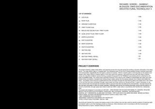
- 66. Richard Gorzki - Byung Kim Ralph Valencia - Harsh Bavishi Scale at A1 Course Code Group No./Name Due Date Project number Project Address 133 Mary Street - Brisbane City QLD 4000 Imaginary School of Architecture - COVE 10/Tecktonics BLDG3220 Coordinator Chris Landorf 10 November, 2016 Assignment 3 Project Name Client The University of Queensland Sheet Title Project Logo Sheet Number 1 : 5 A1CD.503 No. Description Date 1 : 5 Atrium Balustrade Joint Detail (AXO) 2 1 : 5 Atrium Balustrade Section Cut 1 - 2. The double glass panel is slotted between the rubber gaskets, placed between the inner aluminium framing and the curved alunimium casing, which the two are then fastened by the third 30MM bolt. 30MM BOLT DOUBLE GLASS PANEL RUBBER SEAL STEEL HANDLE ALUMINIUM CASING RUBBER GASKET INNER ALUMINIUM FRAMING INT. GLASS THICKNESS: 16-20MM EXT. 1. Inner aluminium framing is bolted onto the concrete slab to ensure secure installation of the balustrade system. The maxinmum length of the framing is dependent on the length of the slab, specified by the manufacturer to meet the requirements of the balustrade system. 3. The pre-made steel handle with the inner rubber seal is then placed on the double glass panel to ensure a safe hand-rail system without exposing the glass edge. Also further creates bonding force for the double glass panel. The glass balustrade spans 1000mm with steel rods dividing the glass and providing support for the glass. Balustrade Section Detail
- 67. Richard Gorzki - Byung Kim Ralph Valencia - Harsh Bavishi Scale at A1 Course Code Group No./Name Due Date Project number Project Address 133 Mary Street - Brisbane City QLD 4000 Imaginary School of Architecture - COVE 10/Tecktonics BLDG3220 Coordinator Chris Landorf 10 November, 2016 Assignment 3 Project Name Client The University of Queensland Sheet Title Project Logo Sheet Number 1 : 5 No. Description Date 1 : 5 Atrium Ceiling Joint Detail (AXO) 1 1 : 5 Atrium Ceiling Section Cut 2 LOW E THERMOPANE UNIT BUTAL TAPE SEALANT PVC DRAFT SEAL WEEPING HOLES SELF-TAPPING SCREWS ALUMINIUM MAIN FRAME COUNTER FLASHING 1.5” WOODEN CURB SHINGLES AIR TUNNELS CAULKING PVC RIGID VINYL THERMAL BARRIER 0.5” AIR SPACE INT. EXT. 1.1.5” Wooden curb is placed onto the edge of the singles on top of the concrete slab to provide support for the heavy aluminium mainframe & low thermopane unit (glass system) 2.1.5” Wooden curb is wrapped by step flashing & counter flashing to protect the component from dampness . 3. Aluminium mainframe is placed on top of the wooden curb to provide structural support. 4. Airtunnels on top of the mainframe provide air pressure equalisation to ensure water does not seep through the frame. Weeping holes assist in the same role to create equal pressure on the both exterior and interior of the structure. 5. Low E thermopane unit is placed between the main frame and retainer frame, with 0.5” air space which allows for temperature regulation and condensation regulation. INT. EXT. A1CD.503.1 Atrium Ceiling Detail
- 68. Richard Gorzki - Byung Kim Ralph Valencia - Harsh Bavishi Scale at A1 Course Code Group No./Name Due Date Project number Project Address 133 Mary Street - Brisbane City QLD 4000 ABBREVIATIONS Imaginary School of Architecture - COVE 10/Tecktonics BLDG3220 Coordinator Chris Landorf 10 November, 2016 Assignment 3 Project Name Client The University of Queensland Sheet Title Project Logo Sheet Number 1 : 100 12 No. Description Date 1 : 50 6th Floor Fire Isolated Staircase Plan 4 1 : 100 Stair- Section 1 5 1 : 50 Basement Fire Isolated Staircase Plan 1 1 : 50 Ground Floor Fire Isolated Staircase Plan 2 1 : 50 1st-5th Floor Fire Isolated Staircase Plan 3 1 2 3 4 5 6 7 8 9 10 11 12 13 11 15 17 18 19 20 21 22 23 24 25 26 16 UP D01 WT4 FIRE STAIR CONC D01 1 2 3 4 5 6 7 8 9 10 11 12 13 11 15 17 18 19 20 21 22 23 24 25 26 16 UP D01 WT4 FIRE STAIR CONC Ground Floor 4236 Level 1 9236 Level 2 13236 Level 3 17236 Level 4 21236 Level 5 25236 Level 6 29236 A - --- Level 7 - Roof 33246 1 : 100 Stair - Section 2 6 Basement FHR FHR UP CONC CONC FIRE STAIR UP 1 2 3 4 5 6 7 8 9 10 11 12 13 14 15 16 17 18 19 20 2 3 4 5 6 7 8 9 10 11 12 13 14 15 16 17 18 19 20 210 2400 286 286 5900 200 210 2400 286 210 2400 286 210 2400 286 286 5900 200 Fire-Isolated Stair Details FHR FHR 286 4900 200 286 4900 200 FHR Fire Hydrant Reel WT4 210mm Thick 200 Core-Filled Concrete Block 10mm Concrete Render - External Clad 10mm Gyprock Aquachek - Internal Clad D01 Single Timber Door - Timber Frame 915 x 2134 D01 D01 WT1 WT1 WT1 WT3 WT1 286mm Thick 200 Core-Filled Concrete Block FRL Insulation - 240m R0.54 10mm Gyprock Plus Plasterboard -Internal Clad 13mm Gyprock Standard Plasterboard -External Clad WT3 190mm Thick 200 Core-Filled Concrete Block Retaining Earth on Basement and GroundLevels Concrete Blockwork Exposed Internally 1 : 50 & WT1 WT3 WT4 WT4 B1 B1 B1 Balustrade 1 - Steel Rail
- 72. A 1 C D . 5 0 4 4 L o u v e r 5 7 8 W0 1 : D o u b l eL o u v e rP a n e l -w / 1 0 0 mm C e n t r eS t e e l Mu l l i o n 1 3 0 0x 1 9 2 0 S L B 1 :1 5 0 MM O n e Wa y C o n c r e t e S l a b ( I n - s i t u e ) w / 3 0 0 MME d g eT h i c k e n i n g . R e f e r R e f e r t oS t r u c t u r a l E n g i n e e r f o r S p a na n d R e i n f o r c i n g C T W : L y s a g h t I n t e r l o c k C a t w a l k I G U :I n s u l a t e d G l a s s P a n e l3 0 mm I G U p a n e l w / 1 6 mma i r g a pU = 1 . 4 W0 2 :W0 2 :F i x e d D o u b l e G l a z e d P a n e l 3 5 mm- Wi t h i nWT 2 1 8 4 0x 1 9 2 0 1 8 4 0x 1 9 2 0 A WN : A WN- G l a s s A w n i n g( R e f e r t oD e t a i l A 1 C D . 4 0 2 ) P F : P e r f o r a t e dF a c a d eP a n e l ( R e f e r t oD e t a i l s A 1 C D . 4 0 4 S P: R H SS t e e l S u p p o r t ( R e f e r t oD e t a i l A 1 C D . 4 0 2 ) T R : T R : T R -T e n s i o nR o dS u p p o r t( R e f e rt o D e t a i l A 1 C D . 4 0 2 ) WT 5 : S p e c i f i c a t i o nf o r I n t e r n a l Wa l l s : ( WT 5 ) 9 0 mmT h i c k I n t e r n a l a n dE x t e r n a l C l a d( a n y o r d e r ) : 5 mm C e mi n s e a lWa l l b o a r d a n d 1 3 mm G y p r o c k F y r c h e k P l a s t e r b o a r d I n s u l a t i o n : I n s u l a t i o n : T S B 3 / A S B 3P o l y e s t e rB e t w e e n 5 1 mmS t u d( 0 . 5 B MT ) A c o u s t i c : 4 8 / 4 1 W0 1
- 73. A 1 C D . 5 0 4 4 L o u v e r 5 7 8 W0 1 : D o u b l eL o u v e rP a n e l -w / 1 0 0 mm C e n t r eS t e e l Mu l l i o n 1 3 0 0x 1 9 2 0 S L B 1 :1 5 0 MM O n e Wa y C o n c r e t e S l a b ( I n - s i t u e ) w / 3 0 0 MME d g eT h i c k e n i n g . R e f e r R e f e r t oS t r u c t u r a l E n g i n e e r f o r S p a na n d R e i n f o r c i n g C T W : L y s a g h t I n t e r l o c k C a t w a l k I G U :I n s u l a t e d G l a s s P a n e l3 0 mm I G U p a n e l w / 1 6 mma i r g a pU = 1 . 4 W0 2 :W0 2 :F i x e d D o u b l e G l a z e d P a n e l 3 5 mm- Wi t h i nWT 2 1 8 4 0x 1 9 2 0 1 8 4 0x 1 9 2 0 A WN : A WN- G l a s s A w n i n g( R e f e r t oD e t a i l A 1 C D . 4 0 2 ) P F : P e r f o r a t e dF a c a d eP a n e l ( R e f e r t oD e t a i l s A 1 C D . 4 0 4 S P: R H SS t e e l S u p p o r t ( R e f e r t oD e t a i l A 1 C D . 4 0 2 ) T R : T R : T R -T e n s i o nR o dS u p p o r t( R e f e rt o D e t a i l A 1 C D . 4 0 2 ) WT 5 : S p e c i f i c a t i o nf o r I n t e r n a l Wa l l s : ( WT 5 ) 9 0 mmT h i c k I n t e r n a l a n dE x t e r n a l C l a d( a n y o r d e r ) : 5 mm C e mi n s e a lWa l l b o a r d a n d 1 3 mm G y p r o c k F y r c h e k P l a s t e r b o a r d I n s u l a t i o n : I n s u l a t i o n : T S B 3 / A S B 3P o l y e s t e rB e t w e e n 5 1 mmS t u d( 0 . 5 B MT ) A c o u s t i c : 4 8 / 4 1 W0 1
- 75. BLDG 1220 RICHARD GORZKI / DRAWING SUBMISSION 1 10/09/17
- 76. BLDG 1220 RICHARD GORZKI / DRAWING SUBMISSION 1 10/09/17
- 77. WK 2 - Section 2 / 1:50 WK 2 - Section 1 / 1:50 BLDG 1220 RICHARD GORZKI / DRAWING SUBMISSION 1 10/09/17
- 78. WK 2 - Wall Isometric / 1:50 BLDG 1220 RICHARD GORZKI / DRAWING SUBMISSION 1 10/09/17 Retaining Wall Platform Wall
- 79. Retaining Wall Retaining Wall WK 3 - Plan / 1:50 BLDG 1220 RICHARD GORZKI / DRAWING SUBMISSION 1 10/09/17 14.5 M 15. 5 M 15 M 14M 15.5 M RL for Platform 16M
- 80. WK 3 - Section 1 / 1:50 WK 3 - Section 2 / 1:50 BLDG 1220 RICHARD GORZKI / DRAWING SUBMISSION 1 10/09/17 Soft Bearer Ceiling Joist Lintel Jam Stud Fascia Hanging Beam Common Stud Rafter Hanging Beam Ceiling Joist Rafter Jamb Stud Jack Stud Jack Stud Top Wall Plate Rafter Top Wall Plate Bearer
- 81. 1008 2394 2390 1141 2709 399 6968 WK 3 - Elevation 1/ 1:50 WK 3 - Elevation 2 / 1:50 3200 2285 BLDG 1220 RICHARD GORZKI / DRAWING SUBMISSION 1 10/09/17
- 82. 929 2278 2237 1254 6698 1130 2692 968 2260 2700 FEMALE BATHROOM MALE BATHROOM PAVILION UNDERCROFT LINE OF ROOF LINE OF GUTTER DWP 745 7443 Wk 3 - Floor Plan / 1:50 6820 BLDG 1220 RICHARD GORZKI / DRAWING SUBMISSION 1 10/09/17
- 83. DWP DWP LINE OF GUTTER 6445 3377 WK 3 - Roof Plan / 1:50 BLDG 1220 RICHARD GORZKI / DRAWING SUBMISSION 1 10/09/17
- 84. BLDG 1220 RICHARD GORZKI / DRAWING SUBMISSION 1 10/09/17 WK 3 - Model Photos
- 85. WK 4 - Iso of Stool BLDG 1220 RICHARD GORZKI / DRAWING SUBMISSION 1 10/09/17 1:5
- 86. 85 450 85 450 450 85 450 85 95 410 95 410 27 72 27 72 42 300 300 42 BLDG 1220 RICHARD GORZKI / DRAWING SUBMISSION 1 10/09/17 11 56 8 7 6 5 4 3 2 1 11 56 11 11 56 11 56 11 56 11 11 56 56 56 90 12 90 12 5 53 STOOL SEGMENT PLAN 5 53 5 53 5 53
- 87. DECK NORTH POOL SOUTH WESTERN WINDS SUN EXPOSURE - Desirable for winter heating -Position of sun in the sky allows easy shading -North Facing walls and windows receive more solar radiation in the winter months. - Longer walls on the Northern Face to minimize exposure in the winter months and maximise it in the summer months. NORTHERN ORIENTATION TREE CANOPIES PROVIDE SHADING FROM EASTERLY SUN Neighbouring property buffers prevailing sun from the west. WK 6 - PLAN DIAGRAM: Siting and Orientation BLDG 1220 RICHARD GORZKI / DRAWING SUBMISSION 1 10/09/17
- 88. WINDOW WALL (GLAZING = HEAVY) STUD FRAMING (TIMBER FRAMING= LIGHT) BLOCKWORK WALL: (MASONARY= HEAVY) WK 6 - PLAN DIAGRAM: Heavy walls vs framed walls / 1:50 BLDG 1220 RICHARD GORZKI / DRAWING SUBMISSION 1 10/09/17
- 89. BEDROOM WR STUDY LIVING BRIDGE Window Wall Large glazed units create a sense of openess and open the home up to Natural Ventilation Blockwork Walls work as the loadbearing structure for the weight of the glazing Blockwork sustains the load of the roof and stud frame structure above. Stud Framing Window Skillion Roof Joists Plasterboard Stud frame construction is light and flexible, allowing the mass to have more extrusions . The Catwalk structure works as a lightwieght platform within the space. WK 6 - SECTION A: Structural Systems 1:50 BLDG 1220 RICHARD GORZKI / DRAWING SUBMISSION 1 10/09/17
- 90. BEDROOM BATHROOM WARDROBE RUMPUS ROOM GLASS LOUVERS Stud Wall Blockwork Wall Skillion Roof Glazing Plasterboard Blockwork Wall Stud Wall Joists Stud frame construction is light and flexible, allowing the mass to have more extrusions . Blockwork Wall provides adequite loadbearing support to the stud wall framed structure and skillion on the first floor. Blockwork Wall provides adequite loadbearing support to the stud wall framed structure and skillion on the first floor. Stud Wall Timber Joist floor system . Engineered Timber Joist floors WK 6 - SECTION B: Structural Systems / 1:50 BLDG 1220 RICHARD GORZKI / DRAWING SUBMISSION 1 10/09/17
- 91. TIE DOWNS Are inserted in the corners, joining wall to roof, supporting the components BRACING Bracing is placed in the external walls preventing racking from prevailing winds from the South, West BRACING Bracing is placed in the external walls preventing racking from prevailing winds from the South West TIE DOWNS Are inserted in the corners, joining wall to roof, supporting the components. BLDG 1220 RICHARD GORZKI / DRAWING SUBMISSION 1 10/09/17 WK 6 - BUILDING BRACING / 1 : 50
- 92. External Plasterboard Internal Plasterboard BLDG 1220 RICHARD GORZKI / DRAWING SUBMISSION 1 10/09/17 WK 6 - BUILDING LINING : Internal Vs External / 1:50
- 93. Damp Proof Membrane: - The Damp proof membrane protects the concrete slab from mositure attack that would result in degradation of the slab, such as: - Cracking - Damaging expansion The Stud wall is covered by a plasterboard rainscreen protecting the structure from: -Water infiltration -Ultra-violet radiation -Negative wind pressures -Heat transfer into and out of the building -Air infiltration -Vapor transmission BLDG 1220 RICHARD GORZKI / DRAWING SUBMISSION 1 10/09/17 WK 6 - Weatherproofing Diagram / 1:50
- 95. BLDG 1220 RICHARD GORZKI / DRAWING SUBMISSION 2 10/09/17 Axonometric Bargeboard Bargeboard Bargeboard Stirrup Concrete Pier Concrete Pier Concrete Pier Stirrup Joist Sill Former Bearer Lintel Bearer Outrigger Solid Blocking Bargeboard Post Post Post Post Balustrade Stump
- 96. BLDG 1220 RICHARD GORZKI / DRAWING SUBMISSION 2 10/09/17 14.50M 15.00M 15.50M 16.00M 16.50M RL 15.50M Retaining Wall Retaining Wall Pavilion Decking A B C D E 1 2 3 4 A B C D E 1 2 3 4 N
- 97. WK 7 - Section 2 - 1:50 WK 7 - Section 1 - 1:50 Blockwork 390mmx 190mm Rebar Wire Slab on ground Edge Beam Blockwork 390mmx 190mm Rebar Wire Compacted Sand Blockwork 390mmx 190mm Rebar Wire Slab on ground Edge Beam BLDG 1220 RICHARD GORZKI / DRAWING SUBMISSION 2 10/09/17
- 98. 16 Degrees 16 Degrees DWP Line of box gutter Slope 3 Degrees 16 Degrees 16 Degrees 3460 8849 5597 2817 236 259 BLDG 1220 RICHARD GORZKI / DRAWING SUBMISSION 2 10/09/17 Roof Plan 1:50 RT RT SF B B SF O NOTES All timber members F5 Unseasoned Cypruss hardwood refer to appendix for all span tables For Lintel sizes refer to Sections Bargeboard Outrigger Blocking 5597mm L x 100mm W x 200mm D 5597mm L x 100mm W x 200mm D 3460mm W x 100mm D x 200mm D
- 99. 2641 3963 7853 P A V I L I O N 4345 6444 T I M B E R D E C K I N G T I M B E R D E C K I N G T I M B E R D E C K I N G T I M B E R D E C K I N G B2 B3 B1 J6 J5 Bearer P1 P2 P3 P4 P5 P6 P7 P8 P10 P11 P12 P14 P15 P16 P9 P13 J4 J3 J2 J7 J1 3963mm x50mm 3926mm x50mm 3926mm x50mm 3222mm x50mm B4 B5 B6 B7 B8 B9 B10 3222mm x50mm J8 J9 J10 J11 J12 J13 J14 BLDG 1220 RICHARD GORZKI / DRAWING SUBMISSION 2 10/09/17 Floor Framing Plan 1:200 A B C D E 1 2 3 4 A B C D E 1 2 3 4 NOTES All timber members F5 Cyprus Unseasoned hardwood refer to appendix for all span tables For Lintel sizes refer to Sections Post No. P1, P2 , P3 P4, P5 , P6 P7, P8 , P9 565mmx50mm 565mmx50mm 600mmx50mm P10, P11, P12, P13, P14, P15, P16 600mmx50mm Dimensions Bearer No. Dimensions 1, 2 3,4 5, 6 7,8 9,10 Joist No. Dimensions 2641mm x 50mm 1,2,3,4,5,6, 7 8,9,10,11,12 2641mm x 50mm
- 100. Lintel Bearer Post Stirrup Joist Stump Ballustrade Lattice Concrete Pier Bargeboard Blocking Blocking Bargeboard Ridge Beam Beam Beam Blocking Lattice Joist Stump Stirup Concrete Pier Steel Post Bearer Lintel Post Lattice 60mm x 180mm 60mm x 180mm 60mm x 180mm 60mm x 180mm 73mm x 142mm BLDG 1220 RICHARD GORZKI / DRAWING SUBMISSION 2 10/09/17 Outrigger Beam Section One Section Two 1:50 1:50 NOTES All timber members F5 Cypress Unseasoned hardwood -refer to appendix for all span tables For Lintel sizes refer to Sections Lintel Bearer Beam Blocking Ridge Beam
- 101. BLDG 1220 RICHARD GORZKI / DRAWING SUBMISSION 2 10/09/17 Model Photo One Model Photo Two Model Photo Three
- 102. BLDG 1220 RICHARD GORZKI / DRAWING SUBMISSION 2 10/09/17 TOOWONG AFRICAN RESTURANT Location : 1/5 Milton Street, Toowong Plan : Existing Building Section : Concrete Pier Steel Post Parrellel Chord Truss triangulated structure Structural Tubing 200mm D Cap Plate bolted at junction of structural tubing End Plate and anchor bolt Steel fascia framing braces truss structure Steel fascia frames truss structure and braces the triangulated structure preventing torsion 1:100 1:100 DEAD LOAD, WIND LOAD Cap Plate End Plate Connection Details Steel Plate 100mm Bolts Steel Rod 100mm Steel Plate Hex bolts Screw
- 103. BLDG 1220 RICHARD GORZKI / DRAWING SUBMISSION 2 10/09/17 NEW FARM FERRY TERMINAL Location : 17 Macarther Avenue, New Farm Plan : 1:100 Section 1:100 Connection Details SHS SHS SHS Welding SHS SHS End Plate Held with steel triangulaed brace plate to prevent torsion from the current of the river SHS SHS Pratt Truss Canvas Sail Pratt Truss Canvas Sail SHS SHS 18.5m 2.5m Canvas Sail DEAD LOAD LIVE LOAD Pratt Truss Detail SHS SHS SHS KEY: SHS Beam
- 105. FRONT ELEVATION E = P/M 10.3 = 140 1450 Inclined End Post Inclined End Post Top Chord Hip Vertical Lower Chord Top Chord truss substructure Diagonal strut substructure Portal strut Top Chord Portal Bracing Top Lateral Bracing Floor Beam SPAGHETTI BRIDGE SIDE ELEVATION BLDG 1220 RICHARD GORZKI / DRAWING SUBMISSION 2 10/09/17
- 106. TORSION occured at the bracing of stringers and the struts 2. Thicken diameter of end posts to reduce: BENDING was created at the end posts HORIZONTAL SHEAR O N E T W O T H R E E 1. Strengthen the bracing attached to the stringers to reduce: Primary: Strengthen structural elements of the bridge floor where the weight is carried to prevent / delay the effects of derformation under the applied load. Secondary: To reduce horizontal shear deformation increase spans of hip verticals and increase bracing. DESIGN IMPROVEMENTS was created at the end posts HORIZONTAL SHEAR 3. Thicken stringers and increase count to four to reduce: force caused deformation to stringers of the bridge and was the primary defect TORSION TORSION BENDING 4. Increase hip vertical count to reduce: BENDING BLDG 1220 RICHARD GORZKI / DRAWING SUBMISSION 2 10/09/17