1. US 20070186684A1
(19) United States
(12) Patent Application Publication (10) Pub. No.: US 2007/0186684 A1
Pham (43) Pub. Date: Aug. 16, 2007
(54) VIBRATING TUBE MASS FLOW METER Publication Classi?cationqa
(51) Int. Cl.
(76) Inventor: Nghieu Q. Pham, (US) G01F 1/84 (2006.01)
(52) US. Cl. ........................................................ 73/861357
Correspondence Address:
TIFFANY & BOSCO (57) ABSTRACT
CAMELBACK ESPLANADE H’ THIRD A vibrating tube meter measures the density, mass ?oW rate
FLOOR or viscosity of a ?uid material including a vibration section.
2525 EAST CAMELBACK ROAD An exciter induces vibrations in the tube vibration section at
PHOENIX, AZ 85016 (Us) a resonance frequency. A motion sensor detects motion of
the tube from the induced vibrations. A helical coil spring
has opposing ends coupled to the tube With the tube posi
(21) Appl. No.: 10/565,915 tioned Within the interior of the coil spring. An external
housing is rigidly coupled to the tube inlet end and outlet end
(22) PCT Filed: Jul. 26, 2004 and has a mass selected to provide a suitable nodal mass for
the tube vibration section and spring element. Temperature
(86) PCT NO-I PCT/US04/23941 sensors are coupled to the tube, the spring element and the
external housing. A pressure sensor is coupled to the tube. A
§ 371(c)(1), processor includes a drive ampli?er and a novel adaptive
(2), (4) Date: Jan. 24, 2006 ?lter and processes signals form the sensors. A novel vis
cosity integrator processes signals from the motion sensors,
Related US. Application Data temperature sensors and the pressure sensor to accurately
calculate density, mass ?oW rate and viscosity of the ?uid
(60) Provisional application No. 60/490,368, ?led on Jul. material as Well as percent concentration of a solute in the
24, 2003. ?uid material.
4" 10
40a 24
28a
/ 12 /22a2o 30b 40c 26 42
30a 40b 306 I 22b
28b
' i / l6
-J!~= H l __ n‘ _J-I“ r r 4:’- -r- ___
L .
29b
18
4: Fluid characteristics
M
DriverAmpli?er
3
Userluputs 1‘ t ,
i5. frequency’ phase’ Adaptive Filter Viscosity Integrator
amplimde M 3-6
Processer
Bl
2. Patent Application Publication Aug. 16, 2007 Sheet 1 0f 5 US 2007/0186684 A1
um
88%25bionic,
mm
55%02328..
2539568%.bvcuswum
NM
55384.535
~.UHH
4. Patent Application Publication Aug. 16, 2007 Sheet 3 of 5 US 2007/0186684 A1
Read measurement (Dn) value
v
Retrieve upper limit (x)
and lower limit (y)
1.0.6
Start out oflimit duration timer
“3:21:58? was Previwé reading Startdebounc timer _
(Dn-l) between limits? 'Reset out oflimit interval timer
mg 112
Update limits
(1: and y)
115
Start out of limit '
interval timer Read out oflimitd
Reset out oflimit _ duration time
duration timer 1A! '
11.8
exceeded
debounoe
Read out oflimitd
interval time
12
time exceeded max '
allowed duraion
Has out .
oflimit inberv ‘ “32'
time exceeded No
max allowed .
interval time? Accept rwdme as
m valid ‘
12.9.
Yes
Discard reading 4 l V
12.
Update moving average .
ofvalid readings V pmv‘ggutpm
m
FIG. 3
7. US 2007/0186684 A1
VIBRATING TUBE MASS FLOW METER
RELATED APPLICATION DATA
[0001] This application is based on and claims the bene?t
of US. Provisional Patent Application No. 60/490,368 ?led
on Jul. 24, 2003, the disclosure of Which is incorporated
herein by this reference.
BACKGROUND
[0002] This invention relates to direct mass ?oWmeters.
More particularly, it concerns mass ?oWmeters ofthe vibrat
ing tube type.
[0003] For some time, vibrating tube mass densitometers
and mass ?oWmeters have been routinely used to directly
measure mass and mass ?oW rate characteristics of ?uids.
Mass ?oWmeters (or direct mass ?oWmeters) have sensing
means that respond uniquely to mass ?oW rate. Other
?oWmeters employ, for example, sensing means that
respond to differential pressure or ?uid velocity. Ifone needs
to measure mass ?oW rate With such devices one must
perform separate measurement of density and infer some
?oW distribution pattern in the cross section ofthe meter and
also infer ?uid ?oW pattern, such as turbulence. They also
require NeWtonian ?uid behavior, Which is often not met.
Thus for reason of measurement simplicity alone, the direct
mass ?oWmeters are very desirable. Other ?oWmeters gen
erally lend themselves much better to volume ?oW rate
measurement than to mass ?oW measurement. In practice,
the mass ?oW measurement is much more useful because
chemical reactions require blending of proportional mass
rather than volume ofingredients and product speci?cations
mostly refer to mass percentage of ingredients not volume
percentage. This represents another major advantage of
direct mass ?oW measurement over other techniques.
[0004] Most vibrating tube mass ?oWmeters operate by
using the principle of the Coriolis e?fect. One type employs
a substantially straight vibrating tube, the other a curved or
looped vibrating tube. Additionally, there are mass ?oWme
ters With one vibrating tube and there are mass ?oWmeters
With tWo vibrating tubes. Those mass ?oWmeters utiliZing
tWo tubes permit either parallel or series ?oW of the ?uid
through the meter. In recent times, vibrating tube meters
employing only one essentially straight vibrating tube have
become more popular in the industry. Compared to mass
?oWmeters using either tWo straight measuring tubes or one
looped measuring tube, vibrating tube type mass ?oWmeters
With only one straight measuring tube o?fer signi?cant
advantages. The primary advantage that single tube mass
?oWmeters hold over mass ?oWmeters With tWo measuring
tubes is that the single tube designs do not require a ?oW
divider or ?oW combiner, the presence ofWhich adds cost to
the device, disturbs the ?oW ofthe ?uid Within the tube, and
complicates the measurement process. Compared to single
or dual looped vibrating tube devices, the main advantages
of the straight vibrating tube design are that it is easier to
manufacture than the looped or curved versions, there is less
?uid pressure drop in a straight tube than in a looped tube,
and a straight tube is easier to clean than a looped tube.
[0005] Vibrating tube ?oWmeters are often referred to as
Coriolis-e?ect ?oWmeters or Coriolis ?oWmeters, and are
direct mass ?oWmeters. Single-tube meters employ the
Well-known principle of the e?fect of Coriolis forces on the
Aug. 16,2007
tube as it vibrates and use the in?uence of a pattern of such
forces upon the tube as it carries the ?uid for Which the mass
?oW measurement is sought. The tube is typically part of a
vibrating assembly in a Coriolis mass ?oWmeter. The assem
bly has a set of natural vibration modes, Which may be of a
simple bending, a torsional, a radial or a coupled type. These
naturally resonant vibration modes are largely a function of
the characteristics of the vibrating tube and its contents, as
is Well knoWn in the art. Each tube is driven to oscillate at
resonance in one ofthese natural modes. Fluid ?oWs into the
?oWmeter tube’s inlet and exits the ?oWmeter tube’s outlet.
The natural vibration modes of the vibrating, ?uid-?lled
system are predominantly de?ned by the combined mass and
sti?fness characteristics of the tube material and the ?uid
?oWing Within the tube. A drive excitation force is typically
applied to the tube near the center ofthe tube. This excitation
force is commonly sinusoidal in nature. When there is no
?oW through the ?oWmeter, all points along the tube oscil
late in response to the applied excitation force. The fre
quency of this oscillation is inversely proportional to the
mass of the ?uid contained Within the tube. All points along
the tube oscillate With Zero change in phase di?ference.
When ?uid ?oWs through the tube, Coriolis forces cause a
change in phase di?ference With respect to the static condi
tion, Which occurs betWeen the center of the tube and each
tube end. The phase on the inlet side of the tube lags the
driver, While the phase on the outlet side leads the driver.
Sensors are placed on the tube to produce sinusoidal signals
representative of the motion of the tube. The sensor output
signals are processed to determine the change in phase
di?ference betWeen the sensor locations along the tube. The
change in phase di?ference betWeen tWo sensor output
signals is proportional to the mass ?oW rate of ?uid ?oWing
through the tube. Vibrating tube ?oWmeters operating sub
stantially as described above have become Widely used With
great success.
[0006] Still, this successful utiliZation notWithstanding,
vibrating tube mass ?oWmeters With one straight vibrating
tube possess a variety of limitations in performance and
accuracy. For example, thermal expansion and stress during
operation of the meter cause variations in the measuring
accuracy in a straight vibrating tube mass ?oWmeter. Vibra
tion-dependent characteristics such as the length and elas
ticity of the vibrating assembly vary as a function of the
temperature of the tube as Well as the temperature of the
?uid Within the tube. The temperature-dependent changes
introduce variables into the system resulting in measurement
inaccuracies. In extreme cases, thermal stress can lead to
mechanical defects such as stress-induced cracks in the
measuring tube. Several attempts to compensate for the
e?fects of temperature in vibrating tube ?oWmeters have
been applied in prior art. One such attempt involves the
presence of solid isolation bars substantially parallel to the
?oW tube and rigidly coupled to the ends of the tube. In
another temperature-compensating scheme, a compensating
cylinder is rigidly coupled&to the ends of the tube, the tube
being located along the longitudinal axis of the cylinder. In
still another device, a shell surrounds the tube and is coupled
to the ends of the ?oW tube using diaphragms. Yet another
technique utiliZes length-variation sensors to detect changes
in the tube length and to provide this data for correcting the
length-dependent, vibration-related measurement. These
attempts to mitigate temperature-related variation of vibrat
ing tube mass ?oWmeters have met With limited success.
8. US 2007/0186684 A1
[0007] Another drawback of vibrating tube mass ?oW
meters results from changes in ?uid pressure during opera
tion of the ?oW meter. Fluid pressure change modi?es the
cross-sectional dimension ofthe ?oW tube thereby changing
the ?oW tube’s bending properties. Large pressure changes
that can occur in practice Will jeopardize measurement
accuracy.
[0008] In addition to the effects of temperature and pres
sure on the ?oWmeter performance during operation,
uncompensated variations in the elasticity of the tube are
often introduced during the assembly process. In many
cases, the tube is secured to the remainder of the ?oWmeter
assembly using a heating process. Processes such as braZing
or Welding the tube introduce localiZed heating to the tube
and the tube often becomes annealed or softened in the
heat-affected regions. This annealing causes non-uniformity
in the elasticity of the tube, degrades mechanical quality
factor (Q) of the tube material, Which in turn Weakens the
tube frequency of resonance, and causes instability in ?uid
parameter measurements.
[0009] Acoustic Waves generated by pumps and other
process equipment also can cause considerable deterioration
of vibrating tube ?oWmeter measurements. Frequent tran
sient, random acoustic disturbances often cause similar
problems. The ?oWmeter may lose the ability to distinguish
betWeen forces induced by motion resulting from such
disturbance from the Coriolis forces resulting from a ?oW
rate change. The amplitude of the sensor output signal is
often distorted by such outside disturbances to the point that
the signal cannot be measured accurately using previously
knoWn techniques. In some aerospace applications, for
example, the use of single straight tube Coriolis e?fect type
mass ?oWmeters is made virtually impossible due to sur
rounding vibrations, especially When the aircraft vibration
amplitude approaches a 20 G force, and the frequency
exceeds about 1000 HZ. Vibrations encountered during
airplane take-olf and landings are of such magnitude and
spectral content that they totally mask the vibrations related
to the natural frequency ofthe tube and its ?uid contents and
related to the mass ?oW rate.
[0010] Another problem for vibrating tube ?oWmeters is
entrainment of gases in the ?uid. The gas may be in the form
of visible or microscopic siZe bubbles. Gas entrainment
causes both ?uid density change and change in the coupling
betWeen the ?uid and the Wall ofthe measurement tube. This
coupling is essential for the Coriolis-effect type ?oWmeter.
Generally, state-of-the-art vibrating tube ?oWmeters exhibit
signi?cant to intolerable errors in measurement accuracy
When the gas entrainment reaches a level of 1% to 3%
volume ratio of gas to ?uid. One particular example Where
gas entrainment causes a problem is in the semiconductor
industry. A slurry of nitric acid, silicon, and other materials
is used to polish semiconductor Wafers in a critical step in
the manufacturing process. Hydrogen peroxide is mixed
With the slurry in a critical concentration by mass ratio to
control the pH ofthe mixture. The concentration is measured
using an elaborate system of valves and pump, uses an
expensive, large titration process, and requires high main
tenance. Concentration can be readily measured using a
mass ?oWmeter except that the hydrogen peroxide is very
prone to out gas resulting in entrained gases in su?icient
amounts to render vibrating tube ?oWmeters useless.
Aug. 16,2007
[0011] Attempts are ongoing that strive to reduce the
effects of undesirable tube vibration resulting from outside
acoustical resonances and process vibrations due to other
in?uences as Well as from those induced by entrained gases.
They include various isolation shock absorber schemes that
attempt to isolate the tube from external forces. More
recently, electronic signal processing has been introduced in
an attempt to control the vibration of the tube. Filtering and
drive control circuitry have been added Within the sensor/
drive ampli?er/excitation loop to detect unWanted modes of
vibration and to negate them Within the composition of the
signal that excites the tube. These implementations are
complex and have, to date, had little success. Additionally,
they are unpredictable and not responsive to the problems
caused by gases entrained Within the ?uid in the tube.
[0012] In many applications, vibrating tube mass ?oWme
ters are used in concert With other measurement devices to
provide a multiplicity of information about ?uid properties.
These include, among others, mass, mass ?oW rate, volume
?oW rate, temperature, pressure, viscosity and concentra
tion. The use of a multitude of varying types of meters
presents problems in measurement accuracy and compat
ibility, equipment maintenance and calibration, and capital
and operating expenditures.
[0013] In vieW ofthe above discussion, there exists a need
for a vibrating tube mass ?oWmeter that accurately measures
mass ?oW over a Wide range of operating temperatures.
Accordingly, it is an object of the present invention to
provide such an energy mass ?oWmeter.
[0014] It is another object of the invention to provide a
system and method to reduce the undesirable effects of
localiZed heating of the ?oW tube during the assembly
process.
[0015] Still another object of the present invention is to
provide a vibrating tube mass ?oWmeter that is accurate
despite changes in pressure of the ?uid Within the tube.
[0016] It is yet another object of the invention to provide
a vibrating tube mass ?oWmeter that operates With great
accuracy in the presence of undesirable acoustic and simi
larly generated interference.
[0017] Another object of the invention is to provide for a
mass ?oWmeter that operates With great accuracy When the
?uid Within the ?oWmeter contains entrained gases.
[0018] Still another object of the invention is to provide a
signal processing apparatus and technique that ?lters
unWanted noise and the intrusion of external resonant spikes
from the measured signal Within the ?oW meter, providing
for improved accuracy of direct mass ?oW, density and
viscosity measurements.
[0019] Further, it is an object of the invention to provide
a multivariable energy mass ?oW meter that accurately and
instantaneously provides measurements including but not
limited to ?uid density, ?oW rate, mass ?oW rate, tempera
ture, pressure, concentration, and viscosity.
[0020] It is yet another object ofthe invention is to provide
an energy mass ?oWmeter that directly measures mass ?oW
in harsh environments such as aircraft ?ight, particularly
during take-olf and landing scenarios.
[0021] Additional objects and advantages ofthe invention
Will be set forth in the description that folloWs, and in part
9. US 2007/0186684 A1
Will be apparent from the description, or may be learned by
practice of the invention. The objects and advantages of the
invention may be realized and obtained by the instrumen
talities and combinations pointed out herein.
SUMMARY
[0022] To achieve the foregoing objects, and in accor
dance With the purposes of the invention as embodied and
broadly described in this document, there is provided a
vibrating tube meter for measuring the density, mass ?oW
rate or viscosity of a ?uid material. The meter includes a
holloW tube having an inlet end and an outlet end and
including a vibration section. An exciter induces vibrations
in the tube vibration section at a resonance frequency. A
motion sensor detects motion of the tube from the induced
vibrations. A spring element is coupled to the tube vibration
section betWeen a ?rst end and a second end.
[0023] In one advantageous embodiment, the spring ele
ment comprises a helical coil spring having opposing ends
coupled to the tube With at least a portion of the tube
positioned Within the interior of the coil spring. The vibra
tion section of the tube is generally aligned along a tube
longitudinal axis and the spring element has a longitudinal
axis oriented generally along the tube longitudinal axis. The
vibration section of the tube is generally straight. An exter
nal housing is rigidly coupled to the tube inlet end and outlet
end and has a mass selected to provide a suitable nodal mass
for the tube vibration section and spring element. The spring
element can be selected to have a spring load constant to
isolate the vibration section from vibrations external to the
vibration section and spring. A ?rst isolation member is
attached to the tube near one end ofthe vibration section and
a second isolation member is attached to the tube near
another end ofthe vibration section. The spring element ?rst
end is attached to the ?rst isolation member, and the spring
element second end is attached to the second isolation
member. Preferably, the isolation members comprise ?anges
that are braZed to the tube, the spring element ?rst end is
Welded to the ?rst isolation member and the spring second
end is Welded to the second isolation member. The tube
vibration section and the spring element are selected to have
coe?icients ofthermal expansion that generally match. Tem
perature sensors can be coupled to the tube to sense the
temperature of the tube, to the spring element to sense the
temperature of the spring element, and to the external
housing element to sense the temperature of the external
housing. A pressure sensor can be coupled to the tube to
sense the pressure of ?uid material in the tube. A processor
includes a drive ampli?er and a novel adaptive ?lter. A novel
a viscosity integrator processes signals from the motion
sensors, temperature sensors and the pressure sensor to
accurately calculate density, mass ?oW rate and viscosity of
the ?uid material as Well as percent concentration of a solute
in the ?uid material.
BRIEF DESCRIPTION OF THE DRAWINGS
[0024] The accompanying draWings, Which are incorpo
rated in and constitute a part of the speci?cation, illustrate
the presently preferred methods and embodiments of the
invention and, together With the general description given
above and the detailed description of the preferred methods
and embodiments given beloW, serve to explain the prin
ciples of the invention.
Aug. 16,2007
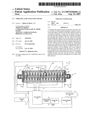
[0025] FIG. 1 is a front elevation in partial cross-section of
one embodiment of a mass ?oW meter according to the
present invention, shoWing the processor in functional block
diagram.
[0026] FIG. 2 is a front elevation in partial cross-section of
a second embodiment of a mass ?oW meter according to the
invention, shoWn Without the processor.
[0027] FIG. 3 is a logical ?oW diagram ofan adaptive ?lter
included in the processor of a ?oW meter according to the
present invention.
[0028] FIG. 4 is a front elevation in partial cross-section of
a composite mass ?oW meter according to the invention,
shoWn Without the processor.
[0029] FIG. 5 is a front elevation in partial cross-section of
another embodiment of a ?oW meter according to the
invention for use in small spaces, shoWn Without the pro
cessor.
DESCRIPTION
[0030] One presently preferred embodiment ofa vibrating
tube mass ?oW meter 10 in accordance With the present
invention is depicted in FIG. 1. The ?oW meter 10 includes
a holloW tube 12, the tube 12 having an inlet end 14 and
outlet end 16 and a generally straight section 18. A spring
element 20 having a ?rst end and a second end is rigidly
coupled to the straight section 18 of the tube 12 by Way of
isolation members 22a and 22b. The ?rst isolation member
2211 is attached to the spring element 20 ?rst end, the second
isolation member 2212 is attached to spring element 20
second end, and both isolation members 2211 and 22b are
attached to the tube 12. An external housing 24 encloses the
tube 12, the spring element 20, and the isolation members
2211 and 22b, and is rigidly coupled to the tube inlet end 14
and outlet end 16. The spring element 20 comprises a helical
coil having a longitudinal axis that is aligned generally along
the longitudinal axis ofthe straight section 18 ofthe tube 12.
[0031] The tube 12, spring element 20, and the isolation
members 22a and 22b combine to form a structure With a
natural resonant frequency. The external housing 24 is of
su?icient mass and rigidity so as to provide a nodal mass
element for the resonant structure. In the presently preferred
embodiment ofthe invention depicted in FIG. 1, the external
housing 24 comprises a housing body 26 and tWo end caps
28a and 28b and is produced from stainless steel, as is
common in the art. The end caps 28a and 28b of this
presently preferred embodiment are manufactured to pro
vide a ?uid interface (ieia ?ange) for ?uid communica
tion betWeen other devices and the tube 12. One of ordinary
skill in the art could envision a variety of materials sand
con?gurations that Would likewise provide a suitable nodal
mass element for the resonant structure. The tube diameter,
lengths and Wall thickness and the tube material are selected
in accordance With criteria normally considered in the
design of a Coriolis mass ?oW meter. The tube 12 of one
presently preferred embodiment is manufactured form stain
less steel, but a variety of other suitable materials including
hastelloy, nickel, tantalum, monel and titanium could also be
used.
[0032] The inclusion of the of the spring element 20 as a
stress relief medium in the resonant structure of the ?oW
meter 10 of the present invention provides several bene?ts
10. US 2007/0186684 A1
to the meter. First, the spring element 20 acts as an isolator
during the ?oWmeter assembly process to reduce the unde
sirable effects of localized heating of the tube 12 during
assembly. Assembly of the resonant structure of the ?oW
meter 10 and its rigid coupling With the external housing 24
preferably is accomplished by braZing the spring element 20
?rst end to the ?rst isolation member 2211, braZing the spring
element 20 second end to the second end isolation member
22b, Welding the ?rst end isolation member 22a to a region
in proximity to a ?rst end of the straight section 18 of the
tube 12, and Welding the second end isolation member 22b
to a region in proximity to a second end of the straight
section 18 ofthe tube 12. During the Welding ofthe isolation
members 2211 and 22b to the tube 12, the spring element 20
functions to reduce the localiZed heating of the tube 10 by
acting as a heat sink to transfer heat aWay from the Weld
Zones and by providing an instant compensating force that
counteracts the expansion and contraction ofthe tube 10 due
to the thermal effects of the Welding. It should be noted
that-in the embodiment of the invention as shoWn in FIG. 1,
the housing end caps 28a and 28b are structured such that
there are free movement Zones 29a and 29b of signi?cant
length present Within housing end caps 28a and 28b. These
free movement Zones are produced by Welding the tube 12
to the housing end caps 28a and 28b a signi?cant distance
(the length of the free movement Zone) from the isolation
members 2211 and 22b. These free movement Zones 29a and
29b reduce the effects ofexternal resonance ofthe ?oWmeter
10. The use of free movement Zones is Well knoWn and
commonly practiced in the art.
[0033] The free expansion and contraction of the spring
element 20 similarly isolate the tube from expansion and
contraction due to any heating When the tube 12 is rigidly
coupled to the external housing 24, as is present during the
Welding, or excessive Welding, of the tube 12 to the external
housing 24 in the presently preferred embodiments of the
invention. Thus, undesirable effects such as the localiZed
annealing of the tube 12 and the introduction of stored
stresses into the tube 12 are mitigated. In a presently
preferred embodiment, the spring element 22 is produced
from spring steel, but a variety of other materials knoWn in
the art may be utiliZed, such as titanium, hastelloy, nickel,
tantalum, or monel. The material from Which the spring
element 22 is produced may be selected using speci?c
design criteria, such that the coe?icient ofthermal expansion
of the spring element 22 reacts in a desired manner With the
coe?icient of thermal expansion of the tube 12 to minimize
the thermal effects on the tube 12 during assembly and
operation. Ideally, the material for the spring should match
that of the vibrating tube material for best performance due
to their identical thermal coe?icients of expansion. During
the operation ofthe ?oWmeter 10, the counteracting force of
the spring element 20 reduces changes in the characteristics
ofthe tube 12 that are due to temperature changes ofthe tube
and the ?uid Within the tube 12, such as changes in elasticity,
diameter, and length, to name a feW.
[0034] Another function of the spring element 20 is to
provide for a higher quality factor, or Q, of the resonant
structure. Spring parameters such as load constant and
length may be chosen to provide a more selective resonant
structure, i.e. a resonant structure With a higher Q. By
increasing the Q ofthe resonant structure, the spring isolates
the structure, and hence the tube 12, from external pertur
bations such as factory equipment noise, ?oor vibrations,
Aug. 16,2007
acoustic impulses, and the like. Testing of this concept has
shoWn a signi?cant reduction in the sensitivity of the meter
10 to external vibration over that of the prior art.
[0035] In addition, by selecting a spring element 20 to
have an appropriate spring constant and by exciting the
spring element 20, such as by a pieZoelectric sensor, using
an active vibration modeling protocol, the spring element 20
can be used to counter noise and external vibration and to
reduce the impact of these on the accuracy of the meter 10.
As Will be apparent to one of ordinary skill in the art,
con?guration other than a helical coil spring could be used
to implement the spring element 20 ofthe present invention.
For example, a leaf spring or a pair of leaf springs may be
used for spring element 20.
[0036] Referring again to FIG. 1, the ?oW meter 10 also
includes a processor 38 comprising a drive ampli?er 32, an
adaptive ?lter 34 and a viscosity integrator 36. Transducers
30a, 30b, and 300 are coupled to the straight section 18 of
the tube 12. TWo transducers 30a and 300 are electrically
coupled to inputs of the drive ampli?er 32. Temperature
sensors 40a, 40b, and 400 are thermally coupled to the
housing 24, the spring member 20, and the tube 12. An
output ofthe drive ampli?er 32 is electrically coupled to the
remaining transducer 30b. The drive ampli?er 32 provides a
signal, Which excites the drive transducer 30b at or near the
expected natural resonant frequency of the resonant struc
ture of the meter 10. This natural resonant frequency is
primarily determined by the tube 12, the spring element 20,
the isolation members 2211 and 22b, and the ?uid Within the
tube 12. The tube resonant structure ofthe meter 10 responds
to this excitation by vibrating. The sensing transducers 30a
and 300 sense the motion of the tube and provide electrical
signals corresponding to this motion to the drive ampli?er
32. A connector (not shoWn) is disposed on the external
housing 24 for coupling the transducers 30a, 30b, and 300 ,
the temperature sensors 40a, 40b, and 400 the pressure
sensor 42 to inputs to the processor 38.
[0037] Another embodiment of the present invention is
illustrated in FIG. 2. In this embodiment, the external
housing 24 includes a top plate 21, a bottom plate 23, tWo
side plates 25a and 25b, and the end caps 28a and 28b. These
components ofthe housing 24 are ?tted to form a rectangular
box for housing the tube 12, the spring member 20, and the
isolation members 2211 and 22b. The tube 12, the spring
member 20, and the isolation members 2211 and 22b are
rigidly coupled as described previously herein. The top plate
21 and the bottom plate 23 are ?xed to the side plates 25a
and 25b such that the top plate 23 is substantially parallel to
the bottom plate 2511 nd substantially perpendicular to the
side plates 25a and 25b and end caps 28a and 28b. The tube
12 protrudes through the end caps 28a and 28b. The pres
ently preferred method for rigidly coupling the top plate 21,
the bottom plate 23, the tWo side plates 25a and 25b , and
the end caps 28a and 28b is Welding. It should be noted that
in this embodiment, the end caps 28a and 28b do not provide
?ttings for coupling the assembly to external ?uid devices.
Fittings 27a and 27b are ?xed to the end caps 28a and 28b
and are shaped to provide for the ?uid coupling of the tube
12 to external ?uid devices. O-rings 50a and 50b are
disposed betWeen end caps 28a and 28b and ?ttings 27a and
27b to provide a ?uid seal for the meter 10. The presently
preferred method for rigidly coupling the end caps 28a and
28b to the ?ttings 27a and 27b is the use of screWs (not
11. US 2007/0186684 A1
shown). This method provides the ?exibility ofchanging the
?ttings 27a and 27b to allow for different ?uid coupling
techniques easily and inexpensively. As in the embodiment
of the invention shoWn in FIG. 1, the transducers 30a, 30b,
and 300 are rigidly coupled to the tube 12, the temperature
sensors 40a, 40b, and 400 are in thermal communication
With the housing 24, the spring member 20, and the tube 12,
and the pressure sensor 42 is in dynamic communication
With the tube 12. The connector (not shoWn) is disposed on
the top plate 21.
[0038] Referring once again to FIG. 1, the drive ampli?er
32 compares the signals provided by the tWo sensing trans
ducers 30a and 300 , and adjusts the frequency of the signal
provided to the drive transducer 30b. A steady-state condi
tion is reached When the frequency ofthe signal provided by
the drive ampli?er 32 to the drive transducer 30b is equal to
the natural resonant frequency of the resonant structure of
the meter 10. In the presence of this steady-state condition,
the signals provided by the sensing transducers 30a and 300
to the drive ampli?er 32 contain frequency, amplitude and
relative phase information. As previously discussed herein,
this information may be used to determine density, viscosity,
and mass ?oW rate of the ?uid Within the tube 12.
[0039] In the presently preferred embodiments of the
invention, the transducers 30a, 30b, and 300 are incorpo
rated using pieZoelectric ceramic devices commonly
employed for this purpose. It should be noted that any of a
variety of embodiments ofthe transducers 30a, 30b, and 300
, including electromagnets, could be implemented by one
skilled in the art. The resonant structure of the meter 10, the
transducers 30a, 30b, and 300 , and the drive ampli?er 32
combine to form a phase locked loop (PLL) oscillator. PLL
oscillators and their characteristics are Well knoWn, and one
of ordinary skill in the art could envision a variety of
embodiments of the drive ampli?er 32 and the PLL oscil
lator.
[0040] An output signal of the drive ampli?er 32 that is
proportional to the signals provided by the sensing trans
ducers 30a and 300 is electrically coupled to the input of the
adaptive ?lter 34. The output signal of the adaptive ?lter 34
is electrically coupled to the input ofthe viscosity integrator
36. The signals provided by the adaptive ?lter 34 and the
viscosity integrator 36 are made available to the processor
38.
[0041] The adaptive ?lter 34 implements a novel signal
processing method that provides a signal to the processor 38
With substantially less noise and feWer spikes than are
present in such signals in previous ?oW meters. These spikes
and noise may result from interfering factory noise,
entrained gas in the measured ?uid, acoustically induced
interference, external vibratory resonances or any of a
variety of undesirable signal-corrupting in?uences.
[0042] FIG. 3 shoWs a logical ?oW diagram for the process
by Which the adaptive ?lter 34 operates. The adaptive ?lter
34 samples the amplitude of one of the signals provided to
it by the drive ampli?er 32 and records the sampled mea
surement (step 104). The signal can be any of the variety of
signals produced by the drive ampli?er 32, Which include
the resonant frequency (Which represents density), the
amplitude of the phase shift (Which represents mass ?oW
rate), and the magnitude of the sensed signal (Which repre
sents ?uid viscosity). It is important to note that the adaptive
Aug. 16,2007
?lter 34 may be used to ?lter any signal provided to it and
Would apply universally to any frequency, phase, or ampli
tude signal. The adaptive ?lter 34 retrieves a stored upper
limit and a loWer limit for the parameter being measured
(step 106) and compares the sampled measurement to the
retrieved upper and loWer limits (step 108). These limits are
initially set by the user but, as explained beloW, are adjusted
as apart of the adaptive ?ltering process.
[0043] The adaptive ?lter 34 then measures the duration of
time that the input signal has been outside the range betWeen
the upper limit and loWer limit or Within the range betWeen
the upper limit and loWer limit. That is, the adaptive ?lter 34
determines the duration of time for Which consecutive
measurements have been betWeen the upper limit and the
loWer limit, or above the upper limit or beloW the loWer
limit. To measure the duration of the aforementioned times,
the adaptive ?lter 34 recalls the previous reading to deter
mine if it Was Within or outside the limit range to see if a
transition has occurred (steps 110, 116). It uses a transition
from an out-of-limit reading to a betWeen-limit reading (or
vice versa) to start one timer and reset another. If the
transition is from an out-of-limit reading to a Within limit
reading, then the ?lter 34 resets an out-of-limit duration
timer and starts an out of range internal timer (step 118).
Conversely, ifthe transition is from a Within limit reading to
an out-of-limit reading, then the ?lter 34 resets the out-of
limit interval timer and starts the out of range duration timer
(step 112).
[0044] The user, as a part of the system initialization,
provides three time limits to be used by the processor 38.
The user sets the maximum alloWable “spike” (out-of-limit
reading) interval time, the maximum alloWable “spike”
duration time, and a time to denounce the reading of a spike.
The ?lter 34 then reads the out-of-limit interval time 122 or
the out-of-limit duration time (step 120) as appropriate and
compares the out-of-limit interval time to the maximum
alloWable out-of-limit interval time (step 128) or compares
the out-of-limit duration time to the maximum alloWable
out-of-limit duration time (step 124), respectively, as set by
the user. The ?lter also compares the out-of-limit duration
time to the denounce time (step 126), Which is also user
de?ned.
[0045] The ?lter 34 then de?nes the current measurement
as valid or invalid by a series of logical decisions based on
Whether the signal is betWeen the upper and loWer limits and
the duration of time for Which this condition has been
present. The present signal is determined to be valid 130 if
the measurement of the signal is betWeen the upper and the
loWer limits and this condition has been present for a time
less than the maximum alloWable “spike” interval time (step
128). The signal is also determined to be valid (step 130) if
the signal is above the upper limit or beloW the loWer limit
and this condition has been present for a greater than
maximum alloWable “spike” duration time (step 126), and if
the signal is above the upper limit or beloW the loWer limit
and this condition has been present for a time greater than
the denounce time (step 124). The signal is determined to be
invalid (step 132) if the signal is betWeen the upper and the
loWer limits and this condition has been present for a time
greater than the maximum alloWable out-of-limit interval
time (step 128). The present signal is also determined to be
invalid if the signal is above the upper limit or beloW the
12. US 2007/0186684 A1
lower limit and this condition has been present for a time
less than the maximum allowable out-of-limit duration (step
126).
[0046] After the ?lter 34 determines that the present signal
is valid, it uses the measurement to re-calculate a moving
average for the subject signal (step) 134. First, an average
measurement is calculated using:
Cav
D"... = Z ux-w/zwnl/wn +1)
1
[0047] Where
[0048] x=the upper limit
[0049] y=loWer limit
[0050] Dn=present reading
[0051] Cavg=number of samples used to average
reading
[0052] Periodically, a moving average of the average of
the readings (Dnavg) is calculated. This moving average is
pavg=(Dnavgl+Dnavg2+Dnavg3+ . . . DDaVgmQ/m. This moving
average is provided by the ?lter 34 for use by the processor
38 and the viscosity integrator 36 and represents reliable
output information for the variable in question Whether it is
mass, mass ?oW rate and the like. In one preferred embodi
ment, ten samples are used to calculate each average (Cnavg=
l0) and one hundred averages are used to calculate the
moving average (m=l00). Excellent results may be
obtained, hoWever, by adjusting the sample population siZe
in accordance With speci?c measurement goals, as Will be
apparent to those skilled in the art.
[0053] The ?lter 34 discards or ignores any present mea
surement determined to be invalid and does not use it (step
132). The ?lter 34 then determines Whether it is time to
update the upper limit and the loWer limit (step 136). The
?lter 34 dynamically updates the upper limit and the loWer
limit (step 114) periodically by adding and subtracting half
the difference betWeen the upper limit and the loWers limit
to the most recent moving average value. The neW limits
used for subsequent ?ltering are:
xnew= x—y)/2+PWg and yneW=Pavg—(x—y)/2
These neW limit values are updated for every ten valid
measurements in the presently preferred method, but any
suitable interval may be used.
[0054] The meter of the present invention can be used
advantageously to measure ?uid viscosity With accuracy.
The amplitude ofthe sensor output is inversely proportional
to the viscosity of the ?uid Within the tube. The amplitude
of the sensor output signal is often distorted by outside
disturbances. Thus, measurement of viscosity using a prior
art vibrating tube ?oWmeter is reduced to measuring the
half-poWer (3dB) amplitude and Width of the corrupted
sinusoidaly shaped sensor output signal. The energy of the
signal (Which is inversely proportional to the viscosity ofthe
?uid) must therefore be calculated based on this ?rst-order
measurement, Which is accurate only When the signal is
virtually non-corrupted. In contrast, the adaptive ?lter ofthe
present invention provides an uncorrupted signal to the
Aug. 16,2007
viscosity integrator 36, Which provides an opportunity to
effectively determine the viscosity of the ?uid With more
accuracy than could be determined in meters ofprior art. The
viscosity of the ?uid Within the tube 12 is inversely propor
tional to the energy of the signal provided by the drive
ampli?er 32 and therefore, also inversely proportional to the
energy of the signal provided by the adaptive ?lter 34. Any
of a variety of methods for determining this energy content
may be used to determine ?uid viscosity, including a voltage
folloWer, an envelope detector or an integrator, to name a
feW. The preferred embodiments ofthe present invention use
a technique that is Widely used in the ?eld of chromatogra
phy, but has not heretofore been used With mass ?oW meters.
This technique involves the use of a voltage folloWer, phase
comparator, recti?er, and integrator netWork for detecting
different type of gases in natural gas pipelines. This tech
nique can be adapted to determine the energy of the signal
provided by the drive ampli?er 32. The viscosity integrator
36 bulfers the sinusoidal output of the adaptive ?lter 32,
phase locks the signal to a reference stored by the processor
38 as a part of the calibration process of the meter 10,
recti?es the phase locked signal, and integrates the recti?ed
signal. The result is compared to data stored by the processor
38 and determines the viscosity of the ?uid by comparison
and cross-correlation to the stored reference information.
[0055] Once again referring to FIG. 1, the temperature
sensors 40a, 40b, and 400 are thermally coupled to the meter
10. Temperature sensor 40a is thermally coupled to the tube
12, thermal sensor 40b is thermally coupled to the spring
element 20, and temperature sensor 400 is thermally coupled
to the external housing 24. The temperature sensors 40a,
40b, and 400 are adapted to sense the temperatures of the
tube 12, the spring element 20, and the external housing 24,
respectively. The temperature sensors 40a, 40b, and 400 are
each electrically coupled to the processor 38 to provide
temperature information pertaining to the meter 10 and to
the ?uid Within the meter. The temperature sensors 40a, 40b,
and 400 utiliZed in the presently preferred embodiments of
the invention are ofthe resistive temperature detector (RTD)
type, but any temperature detection device envisioned by
one of ordinary skill in the art might be employed.
[0056] Pressure sensor 42 is dynamically coupled to the
tube 12. The pressure sensor 42 is adapted to sense the
pressure of the ?uid Within the tube 12. The pressure sensor
42 is electrically coupled to the processor 38 to provide
pressure information pertaining to the ?uid Within the meter
10. The presently preferred pressure sensor 42 is a strain
gauge as is commonly used to detect force that is routinely
used to measure pressure. It Will be understood, hoWever,
and that this is but one of a variety of Ways in Which the
pressure of the ?uid Within the tube 12 may be represented
to the processor 38.
[0057] The processor 38 accepts signals from the adaptive
?lter 34, the viscosity integrator 36, the temperature sensors
40a, 40b, and 400 , the pressure sensor 42, and knoWn ?uid
parameters provided as user inputs 46. The processor 38
measures or computes a variety of parameters related to the
physical characteristics ofthe ?uid Within the tube 12. These
?uid characteristics 44 are made available to the user of the
meter 10 by the processor 38 by any of several means such
as displaying the results to the user, storing the information
in a database, or transmitting the information to a remote
location, to name a feW. The presently preferred embodi
ments of the invention provide information to the user
including the ?uid density, the ?uid mass ?oW rate, the ?uid
13. US 2007/0186684 A1
volume ?oW rate, the ?uid temperature, the ?uid pressure,
the ?uid viscosity, and the percent concentration of the ?uid
by mass. The ?uid temperature and ?uid pressure are
measured directly via the processor 38. Uncompensated
measurements of the ?uid density, the ?uid mass ?oW rate,
and the ?uid viscosity are converted by the processor 38 and
compensated for temperature and pressure.
[0058] A series of mathematical compensation algorithms
is employed by the processor 38 to correct for temperature
di?erences betWeen components of the meter 10 and to
improve the accuracy of the measurement. This is accom
plished by adjusting the mass reading such that the mass is
not only a function of the resultant natural resonant fre
quency of the resonant structure of the meter 10, but such
that the mass is a function of the temperature due to the
effects of temperature on the expected natural resonant
frequency ofthe tube 12. That is, the difference betWeen the
natural resonant frequency of the resonant structure of the
meter 10 at a speci?ed temperature With a knoWn ?uid
present in the tube 12 is calculated as a function not only of
the mass of the ?uid in the tube 12, but of the temperature
characteristics of the meter 10. These temperature charac
teristics are measured under controlled calibration condi
tions and used to adjust the mass reading from the uncom
pensated mass reading, Which ignores the effects of the
temperature of the tube 12 and external housing 24.
[0059] According to a preferred embodiment ofthe inven
tion, the uncompensated mass ?oW rate is calculated by the
processor 38 using a method based on a modi?ed version of
a surface response type model solving three variables:
density, tube temperature, and shell (external) temperature.
The method uses the uncompensated density (D) of the
measured ?uid Which is computed from:
Where C0, C1, and C2 are coe?icients determined during the
meter calibration, and f is the frequency of oscillation
provided by the drive ampli?er.
[0060] The processor then may use any of three separate
temperature compensation algorithms to compute the com
pensated density (Dtl, Dt2, or Dtl3). One temperature com
pensating algorithm available to the user is de?ned by.
Dz1=(T1><D+T2)><(za-zo)+T3><(za-zo)2,
Where T1, T2, and T3 are coe?icients determined during the
meter calibration, ta is the tube temperature as provided by
the temperature sensor 40a coupled to the tube 12, and t0 is
the temperature at Which the calibration of the meter Was
performed
[0061] A second algorithm utiliZes the temperature of the
external housing 24 as provided by temperature sensor 400
of the presently preferred embodiment. The second algo
rithm incorporates the result, Dtl, of the ?rst algorithm and
is of the form:
Where C5 through Cl5 are determined during the meter
calibration and th is the external housing temperature.
Aug. 16,2007
[0062] Another algorithm for temperature compensated
density utiliZes the results ofthe other tWo algorithms and is:
Where Cl6 through Cl8 are determined during the meter
calibration.
[0063] The foregoing temperature compensating method
for determining density produces results over a Wider range
oftemperatures than have methods implemented in previous
?oW meters. By implementing this method, the present
invention provides a novel approach in the calculation ofthe
effects of temperature on ?uid density measurement.
[0064] Similarly, the difference betWeen the natural reso
nant frequency of the resonant structure of the meter 10 at
a speci?ed ?uid pressure With a knoWn ?uid present in the
tube 12 is calculated as a function not only ofthe mass ofthe
?uid in the tube 12, but of the ?uid pressure characteristics
ofthe meter 10. These pressure characteristics are measured
under controlled calibration conditions and used to adjust
the density reading from the uncompensated density read
ing, Which ignores the effects of temperature. Three algo
rithms for determining pressure-compensated ?uid density
are utiliZed by the presently preferred embodiment of the
invention. These algorithms use the results ofthe algorithms
that provide temperature-compensated density readings pre
viously discussed herein.
[0065] One algorithm implemented by the processor 38 to
calculate the pressure-compensated ?uid density is:
Where P1, P2, P3 are coe?icients determined during the meter
calibration. Pa is the pressure reported by pressure sensor 42
to the processor 38, PO is the pressure at Which the calibra
tion of the meter 10 Was performed.
[0066] A further re?ned calculation for the pressure-com
pensated ?uid density is:
[0068] As Will be apparent to one of ordinary skill in the
art, calculations similar to the foregoing calculations for
determining temperature and pressure compensated density
also can be used to calculate the compensated mass ?oW rate
and viscosity.
[0069] The ?uid volume ?oW rate is calculated by the
processor 38 as the ?uid mass ?oW rate divided by the ?uid
density. The percent concentration of the ?uid by mass is
algorithmically computed by the processor 38 utiliZing the
measured ?uid density, the measured temperature of the
?uid, the measured pressure of the ?uid and knoWn volume
and pre-de?ned density information of the dissolved sub
stance as provided by the-user.
[0070] The processor 38 can determine the concentration
of a ?uid solution by accepting and processing the multitude
of readings provided to it by the meter 10, the ?lter 34, the
viscosity integrator 36 as Well as the temperature sensors
41a, 40b, and 400, and the pressure sensor 42. Uncompen
sated readings for concentration level, as Well as temperature
and pressure compensated readings, are computed by the
processor 38. The user inputs to the processor 38 density and
14. US 2007/0186684 A1
volume data for the speci?c components that make up the
solution. The processor 38 then calculates the concentration
ratio using the density measurements from the meter 10. The
uncompensated concentration ratio is computed using:
V x
Concentration ratio : Sn—pm >< CF
(Vw + Vsl + VS2 + Vsn) ><P0
Where VSn is the volume of solute n as provided by the user,
pSn is the density of solute n as provided by the user, VW is
the volume of Water or any other base ?uid of the solution
as provided by the user, pW is the density of Water or base
?uid as provided by the user, p0 is the uncompensated
density as calculated by the processor 38, and CF is a
correction factor for measurement nonlinearities and is
empirically determined during meter calibration.
[0071] A temperature compensated calculation ofthe con
centration ratio is calculated using:
Where CT is the speci?c temperature coe?icient for the base
?uid. This coe?icient is obtained from reference materials as
known in the art. At is the difference in the temperature of
the ?uid from the temperature at Which the density of the
base ?uid Was provided.
[0072] A pressure compensated calculation of the concen
tration ratio is calculated using:
(poxCTxArxCPxAP)
Where CP is the speci?c pressure coe?icient for the base
?uid. This coe?icient is obtained from reference materials as
knoWn in the art. AP is the difference in the pressure of the
?uid from the pressure at Which the density of the base ?uid
Was provided. The pressure and temperature of the ?uid are
provided to the processor 38 by the use of the pressure
sensor 42 and the tube temperature sensor 40a.
[0073] In some applications Where the frequency of exter
nal vibration spectra are of su?icient amplitude, the Coriolis
e?‘ect forces are insu?icient to produce detectable phase
changes relative to the ?uid Zero ?oW condition. These
conditions are present in aircraft, particularly during take-off
and landing conditions and render a Coriolis-effect meter
ineffective in measuring mass ?oW rate due to the meter’s
typical loW operating frequency. FIG. 4 illustrates a com
posite mass ?oW meter 54 according to the present inven
tion, Which can be used for such an application. The com
posite ?oW meter 54 utiliZes the structure of the preferred
embodiment of the mass ?oW meter 10 depicted in FIG. 2.
The second end cap 28b is replaced With a volume ?oW
meter 56. The volume ?oW meter 56 is rigidly coupled to the
top plate 21, the bottom plate 23, and the tWo side plates
such that the tube 12 is in ?uid communication With the
Aug. 16,2007
volume ?oW meter 56. One ofthe ?ttings 27b is then rigidly
coupled to the volume ?oW meter 56 to provide ?uid
combination betWeen the volume ?oW meter 56 and external
?uid devices. The O-ring 50b is dispose betWeen the volume
?oW meter 56 and the ?tting 27b to provide a ?uid seal. The
volume ?oW meter 56 includes a volume ?oW indicator 58,
Which provides a reading of the volume ?oW of the ?uid
Within the tube 12. The volume ?oW indicator 58 is in
communication With the processor 38 of the present inven
tion. The volume ?oW meter 56 may be of any of a variety
of types of volume ?oW meters Well knoWn in the art
including, but not limited to turbine meters, vortex meters,
ultrasonic meters, ori?ce meters and thermal meters.
[0074] The positioning of the volume ?oW meter 56
adjacent the tube 12 provides a measure of volume ?oW of
the ?uid in the tube 12 such that a more accurate measure
ment of ?oW rate can be obtained. The accuracy reducing
effects of connectors, non-laminar ?oW into the volume ?oW
meter 56 and pressure loss in connecting lines, just to
mention feW are avoided in this con?guration. The volume
?oW information provided to the processor by the volume
?oW indicator enables the processor to calculate the mass
?oW rate With relative ease and great accuracy. The mass
?oW rate is the volume ?oW rate multiplied by the density of
the ?uid, the density of the ?uid being proportional to the
resonant frequency of the resonant structure as previously
explained herein.
[0075] FIG. 5 depicts an alternate embodiment of a mass
?oW meter according to the-present invention. This structure
is similar to the ?rst embodiment of the straight tube ?oW
meter 10 discussed above, except that a coiled tube 60 is
used to transport the ?uid and is the predominant resonance
determining device. The coiled tube 60 is rigidly coupled to
the isolation members 22a and 22b. The tube 60 and the
isolation members 2211 and 22b are enclosed in the external
housing 24 and are placed in ?uid communication With
external devices by Way of end caps 28a and 28b. As in the
previously described meters, the transducers 30a, 30b, and
300 are rigidly coupled to the tube 60, the temperature
sensors 40a, and 40b are in thermal communication With the
housing 24 and the tube 60, and the pressure sensor 42 is in
dynamic communication With the tube 60. The connector 48
is disposed on the housing 24. This embodiment of a mass
?oW meter provides a novel con?guration by Which the ?uid
length of the tube 60 is signi?cantly greater then the length
of the housing 24, Which is a critical design requirement for
a Coriolis mass ?oW transducer. This results in a signi?cant
reduction in space as compared to mass ?oW meters ofprior
art, Which is advantageous in a variety of applications
including the aerospace industry.
[0076] From the foregoing, it can be seen that the present
invention provides a number of advantages. A ?oW meter
according to the invention, can accurately measure mass
?oW over a Wide range of operating temperatures. It can
reduce the undesirable effects of localiZed heating of the
?oW tube during the assembly process and provide mass
?oWmeters that are accurate despite changes in pressure of
the ?uid Within the tube. The ?oW meter can operate With
great accuracy in the presence of undesirable acoustic and
similarly generated interference and can operate With great
accuracy When the ?uid Within the ?oWmeter contains
entrained gases. It can utiliZe a signal processing technique
that ?lters unWanted noise from the measured signal Within
15. US 2007/0186684 Al
the ?oWmeter. This method can provide for improved accu
racy of direct mass ?oW, density, and viscosity. The multi
variable mass ?oWmeter according to the invention can
accurately and instantaneously provide measurements
including but not limited to ?uid density, ?oW rate, mass
?oW rate, temperature, pressure, concentration, and viscos
ity. A composite mass ?oW meter according to the invention
can provide directly measure mass ?oW in harsh environ
ments, such as aircraft ?ight, particularly during take-offand
landing scenarios. A coiled tube ?oW meter according to the
invention can provide a space saving embodiment for aero
space applications.
[0077] While certain preferred embodiments and methods
of the invention have been described, these have been
presented by Way of example only, and are not intended to
limit the scope of the present invention. Additional advan
tages and modi?cations Will readily occur to those skilled in
the art. Therefore, the invention in its broader aspects is not
limited to the speci?c embodiments, methods and conditions
described herein, Which are not meant to and should not be
construed to limit the scope of the invention. Accordingly,
departures may be made from such embodiments and meth
ods, variations may be made from such conditions, and
deviations may be made from the details described herein
Without departing from the spirit or scope of the general
inventive concept as de?ned by the appended claims and
their equivalents.
What is claimed is:
1. A vibrating-tube meter for measuring the density, mass
?oW rate or viscosity of a ?uid material, the meter compris
ing:
a holloW tube having an inlet end and an outlet end and
including a vibration section;
excitation means for inducing vibrations in the tube
vibration section at a resonance frequency;
motion sensing means for detecting motion of the tube
from the induced vibrations; and
a spring element coupled to the vibration section betWeen
a ?rst end and a second end of the vibration section.
2. The vibrating tube meter according to claim 1 Wherein
the spring element comprises a helical coil spring having
opposing ends coupled to the tube.
3. The vibrating tube meter according to claim 1 Wherein
the at least a portion of the tube is positioned Within the
interior of the coil spring.
4. The vibrating tube meter according to claim 1 Wherein
the vibration section of the tube is generally aligned along a
tube longitudinal axis and the spring element comprises a
helical coil spring having a longitudinal axis oriented gen
erally along the tube longitudinal axis.
5. The vibrating tube meter according to claim 1 Wherein
the vibration section of the tube is generally straight.
6. The vibrating tube meter according to claim 1 further
comprising an external housing rigidly coupled to the tube
inlet end and outlet end and having a mass selected to
provide a suitable nodal mass for the tube vibration section
and spring element.
7. The vibrating tube meter according to claim 1 Wherein
the spring element is selected to have a spring load constant
to isolate the vibration section from vibrations external to
the vibration section and spring.
Aug. 16,2007
8. The vibrating tube meter according to claim 1 Wherein:
the tube vibration section includes a ?rst isolation mem
ber attached to the tube near one end of the vibration
section and a second isolation member attached to the
tube near another end of the vibration section;
the spring element ?rst end is attached to the ?rst isolation
member; and
the spring element second end is attached to the second
isolation member.
9. The vibrating tube meter according to claim 8 Wherein
the ?rst and second isolation members are braZed to the tube,
the spring element ?rst end is Welded to the ?rst isolation
member and the spring second end is Welded to the second
isolation member.
10. The vibrating tube meter according to claim 1,
Wherein the tube vibration section has a coe?icient of
thermal expansion and the spring element is composed of a
material selected to have a coe?icient of thermal expansion
that generally matches the coe?icient of thermal expansion
of the tube vibration section.
11. The vibrating tube meter according to claim 1,
Wherein the tube vibration section and the spring element are
composed of matching material.
12. The vibrating tube meter according to claim 1,
Wherein the spring element comprises a steel or titanium.
13. The vibrating tube meter according to claim 1,
Wherein the tube includes a curved portion.
14. Atube assembly for a densitometer or mass ?oW meter
or viscometer of the vibrating-tube type, the assembly
comprising:
a holloW tube having a ?rst isolation member coupled
near an inlet end and a second isolation member
coupled near an outlet end;
an excitation device coupled to the tube;
one or more motion sensing devices coupled to the tube;
and
a spring element coupled to the tube betWeen the ?rst and
second internal isolation members.
15. The tube assembly according to claim 14 Wherein the
spring element comprises a helical coil spring having oppos
ing ends coupled to the isolation members.
16. The tube assembly according to claim 14 Wherein the
tube includes a section that is generally straight.
17. The tube assembly according to claim 14 Wherein the
tube includes a section that is generally curved.
18. The tube assembly according to claim 14 Wherein the
spring element is rigidly attached to the isolation members
and the isolation members are rigidly attached to the tube.
19. The tube assembly according to claim 14 Wherein
each of the isolation members comprises a ?ange disposed
around the tube.
20. The tube assembly according to claim 14 Wherein the
isolation members are braZed to the tube and the spring
element ?rst is Welded to the isolation members.
21. The-tube assembly according to claim 14, Wherein the
tube has a coe?icient of thermal expansion and the spring
element is selected to have a coe?icient of thermal expan
sion that generally matches the coe?icient ofthermal expan
sion of the tube.
16. US 2007/0186684 A1
22. The tube assembly of claim 14 farther comprising a
temperature sensor coupled to the tube to sense the tem
perature of the tube.
23. The tube assembly of claim 14 further comprising a
temperature sensor coupled to the spring element to sense
the temperature of the spring element.
24. The tube assembly of claim 14 further comprising a
pressure sensor coupled to the tube to sense the pressure of
?uid material in the tube.
25. The vibrating tube meter according to claim 6 further
comprising a temperature sensor coupled to the external
housing element to sense the temperature of the external
housing.
26. A method for manufacturing a vibrating tube densi
tometer or mass ?oW meter or viscometer, the method
comprising:
providing a holloW tube having an isolation member near
an input end and an isolation member near an output
end;
Aug. 16,2007
coupling one or more excitation devices to the tube;
coupling one or more motion sensing devices to the tube;
and
coupling a spring element to the tube betWeen the internal
isolation members.
27. The method according to claim 26 Wherein the step of
coupling the spring element to the tube comprises braZing
the isolation members to the tube and Welding the spring
element to the isolation members.
28. The method according to claim 26 Wherein the step of
coupling one or more excitation devices to the tube com
prises attaching a piezoelectric transducer to the tube.
29. The method according to claim 26 Wherein the step of
coupling one or more motion sensing devices to the tube
comprises attaching a piezoelectric transducer to the tube.