VRF-Lite: Virtual Routing and Forwarding for Multiple VPNs
•
3 likes•3,529 views

VRF (Virtual Routing and Forwarding) is a technology that allows multiple instances of a routing table to co-exist within the same router at the same time. This increases functionality by allowing network paths to be segmented without using multiple devices. Because traffic is automatically segregated, VRF also increases network security and can eliminate the need for encryption and authentication. Internet service providers (ISPs) often take advantage of VRF to create separate virtual private networks (VPNs) for customers; thus the technology is also referred to as VPN routing and forwarding. Because the routing instances are independent, the same or overlapping IP addresses can be used without conflicting with each other.

Recommended
More Related Content
What's hot
What's hot (20)
Similar to VRF-Lite: Virtual Routing and Forwarding for Multiple VPNs
Similar to VRF-Lite: Virtual Routing and Forwarding for Multiple VPNs (20)
More from Netwax Lab
More from Netwax Lab (20)
Recently uploaded
Recently uploaded (20)
VRF-Lite: Virtual Routing and Forwarding for Multiple VPNs
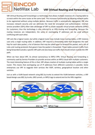
- 1. VRF (Virtual Routing and Forwarding) VRF (Virtual Routing and Forwarding) is a technology that allows multiple instances of a routing table to co-exist within the same router at the same time. This increases functionality by allowing network paths to be segmented without using multiple devices. Because traffic is automatically segregated, VRF also increases network security and can eliminate the need for encryption and authentication. Internet service providers (ISPs) often take advantage of VRF to create separate virtual private networks (VPNs) for customers; thus the technology is also referred to as VPN routing and forwarding. Because the routing instances are independent, the same or overlapping IP addresses can be used without conflicting with each other. VRF acts like a logical router, but while a logical router may include many routing tables, a VRF instance uses only a single routing table. In addition, VRF requires a forwarding table that designates the next hop for each data packet, a list of devices that may be called upon to forward the packet, and a set of rules and routing protocols that govern how the packet is forwarded. These tables prevent traffic from being forwarded outside a specific VRF path and also keep out traffic that should remain outside the VRF path. When we hear about VRF, its almost synonymous to MPLS VPN. Virtual Routing and Forwarding is commonly used by Service Providers to provide services within an MPLS cloud with multiple customers. The most interesting feature of this is that, VRF allows creation of multiple routing tables within a single router. This means that overlapping use of IP addresses from different customers is possible. Some enterprises use VRF to seggrate their services like VOIP, wireless, geographical location and other varieties. Just as with a VLAN based network using 802.1q trunks to extend the VLAN between switches, a VRF based design uses 802.1q trunks, GRE tunnels, or MPLS tags to extend and tie the VRFs together. Figure 1
- 2. VRF (Virtual Routing and Forwarding) VRF-Lite (Multi-VRF) VRF-lite is a feature that enables a service provider to support two or more VPNs, where IP addresses can be overlapped among the VPNs. VRF-lite uses input interfaces to distinguish routes for different VPNs and forms virtual packet-forwarding tables by associating one or more Layer 3 interfaces with each VRF. Interfaces in a VRF can be either physical, such as Ethernet ports, or logical, such as VLAN SVIs, but a Layer 3 interface cannot belong to more than one VRF at any time. It supports multiple, overlapping, independent routing and forwarding tables per customer. Any routing protocol supported by normal VRF can be used in a VRF-Lite CE implementation. The CE supports traffic separation between customer networks. As there is no MPLS functionality on the CE, no label exchange happens between the CE and PE. VRF-lite includes these devices: Customer edge (CE) devices provide customer access to the service provider network over a data link to one or more provider edge routers. The CE device advertises the site's local routes to the provider edge router and learns the remote VPN routes from it. A Catalyst 4500 series switch can be a CE. Provider edge (PE) routers exchange routing information with CE devices by using static routing or a routing protocol such as BGP, RIPv1, or RIPv2. The PE is only required to maintain VPN routes for those VPNs to which it is directly attached, eliminating the need for the PE to maintain all of the service provider VPN routes. Each PE router maintains a VRF for each of its directly connected sites. Multiple interfaces on a PE router can be associated with a single VRF if all of these sites participate in the same VPN. Each VPN is mapped to a specified VRF. After learning local VPN routes from CEs, a PE router exchanges VPN routing information with other PE routers by using internal BGP (iBPG). Provider routers (or core routers) are any routers in the service provider network that do not attach to CE devices. With VRF-lite, multiple customers can share one CE, and only one physical link is used between the CE and the PE. The shared CE maintains separate VRF tables for each customer and switches or routes packets for each customer based on its own routing table. VRF-lite extends limited PE functionality to a CE device, giving it the ability to maintain separate VRF tables to extend the privacy and security of a VPN to the branch office. Packet-Forwarding Process in a VRF-lite CE-enabled network: When the CE receives a packet from a VPN, it looks up the routing table based on the input interface. When a route is found, the CE forwards the packet to the PE.
- 3. VRF (Virtual Routing and Forwarding) When the ingress PE receives a packet from the CE, it performs a VRF lookup. When a route is found, the router adds a corresponding MPLS label to the packet and sends it to the MPLS network. When an egress PE receives a packet from the network, it strips the label and uses the label to identify the correct VPN routing table. The egress PE then performs the normal route lookup. When a route is found, it forwards the packet to the correct adjacency. When a CE receives a packet from an egress PE, it uses the input interface to look up the correct VPN routing table. If a route is found, the CE forwards the packet within the VPN. The VRF-lite network has three major components: VPN route target communities— Lists all other members of a VPN community. You need to configure VPN route targets for each VPN community member. Multiprotocol BGP peering of VPN community PE routers— Propagates VRF reachability information to all members of a VPN community. You need to configure BGP peering in all PE routers within a VPN community. VPN forwarding— Transports all traffic between all VPN community members across a VPN service-provider network. Application Shared Datacenters- The datacenter provider can use VRFs to reduce the number of device involved. Eg. If the datacenter is hosting three different customers (that use similar IP subnets) then there might be a need to three different routers. Figure 2
- 4. VRF (Virtual Routing and Forwarding) But if VRF is used, then only one router can be used. ISP- ISPs provide links between sites of multiple customers. By the use of VRF it is possible to use the same infrastructure for multiple customers. Without VRF Figure 3 Figure 4
- 5. VRF (Virtual Routing and Forwarding) With VRF A tag is added to each route. This tag is called a Route Distinguisher. Figure 5
- 6. VRF (Virtual Routing and Forwarding) Example Configuration (Note: Make Sure R1 and R2 Ping each other.) ISP int f0/0 ip add 101.1.1.1 255.255.255.0 no shut exit int f0/1 ip add 102.1.1.1 255.255.255.0 no shut exit R1 ip cef ip vrf A exit Figure 6 Topology
- 7. VRF (Virtual Routing and Forwarding) int f0/0 ip add 101.1.1.100 255.255.255.0 no shut exit int f0/1 ip vrf forwarding A ip add 192.168.1.1 255.255.255.0 no shut exit ip route 0.0.0.0 0.0.0.0 101.1.1.1 crypto isakmp policy 10 encr 3des authentication pre-share group 2 lifetime 1800 exit crypto keyring KEY pre-shared-key address 102.1.1.100 key cisco exit crypto isakmp profile ISA vrf A keyring KEY match identity address 102.1.1.100 255.255.255.255 exit crypto ipsec transform-set tset esp-3des esp-sha-hmac exit ip access-list extended VPN permit ip host 192.168.1.100 host 192.168.2.100 exit crypto map CMAP 10 ipsec-isakmp set peer 102.1.1.100 set transform-set tset
- 8. VRF (Virtual Routing and Forwarding) set isakmp-profile ISA match address VPN reverse-route static exit int f0/0 crypto map CMAP exit R2 ip cef ip vrf A exit int f0/0 ip add 102.1.1.100 255.255.255.0 no shut exit int f0/1 ip vrf forwarding A ip add 192.168.2.1 255.255.255.0 no shut exit ip route 0.0.0.0 0.0.0.0 102.1.1.1 ip route vrf A 192.168.1.100 255.255.255.255 101.1.1.100 global (or you can use reverse-route static on Crypto map CMAP 10 ipsec-isakmp) crypto isakmp policy 10 encr 3des authentication pre-share group 2 lifetime 1800 exit crypto keyring KEY pre-shared-key address 101.1.1.100 key cisco exit
- 9. VRF (Virtual Routing and Forwarding) crypto isakmp profile ISA vrf A keyring KEY match identity address 101.1.1.100 255.255.255.255 exit crypto ipsec transform-set tset esp-3des esp-sha-hmac exit ip access-list extended VPN permit ip host 192.168.2.100 host 192.168.1.100 exit crypto map CMAP 10 ipsec-isakmp set peer 101.1.1.100 set transform-set tset set isakmp-profile ISA match address VPN exit int f0/0 crypto map CMAP exit Lan1 ip cef ip vrf A exit int f0/0 ip vrf forwarding A ip add 192.168.1.100 255.255.255.0 no shut exit ip route vrf A 0.0.0.0 0.0.0.0 192.168.1.1
- 10. VRF (Virtual Routing and Forwarding) Lan2 ip cef ip vrf A exit int f0/0 ip vrf forwarding A ip add 192.168.2.100 255.255.255.0 no shut exit ip route vrf A 0.0.0.0 0.0.0.0 192.168.2.1