![Email:sales03@istartek.com Whatsapp:+86 13128849769
8 years experiences professional Chinse manufacture for GPS Tracker producing and developing
iStartek VT600 Vehicle Tracker Relay Wiring
Diagram
Engine Cut
Relay Connection: Connect a relay as below picture shows:
Calculate the correct VCC value according to relay’s parameter to comply with the
following requirements:
Output open drain sink voltage (ineffective) 45V max
Output Low voltage sink current (effective) 500mA max
Normally two green wires are connected solidly (P1 and P2 are Normal Close[NC] in the
relay), when output is open (Output be low voltage), two green wires will disconnect, the
engine is then cut.](data:image/gif;base64,R0lGODlhAQABAIAAAAAAAP///yH5BAEAAAAALAAAAAABAAEAAAIBRAA7)
Recommended
More Related Content
Recently uploaded
Recently uploaded (9)
Featured
Featured (20)
How to install a relay?
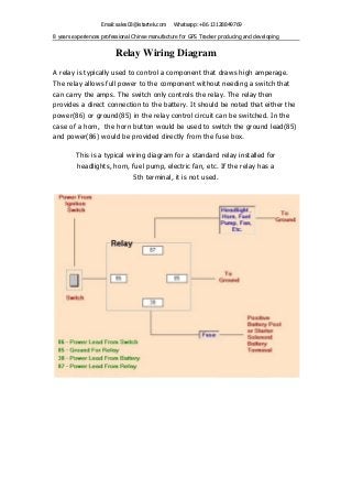
- 1. Email:sales03@istartek.com Whatsapp:+86 13128849769 8 years experiences professional Chinse manufacture for GPS Tracker producing and developing Relay Wiring Diagram A relay is typically used to control a component that draws high amperage. The relay allows full power to the component without needing a switch that can carry the amps. The switch only controls the relay. The relay then provides a direct connection to the battery. It should be noted that either the power(86) or ground(85) in the relay control circuit can be switched. In the case of a horn, the horn button would be used to switch the ground lead(85) and power(86) would be provided directly from the fuse box. This is a typical wiring diagram for a standard relay installed for headlights, horn, fuel pump, electric fan, etc. If the relay has a 5th terminal, it is not used.
- 2. Email:sales03@istartek.com Whatsapp:+86 13128849769 8 years experiences professional Chinse manufacture for GPS Tracker producing and developing iStartek VT600 Vehicle Tracker Relay Wiring Diagram Engine Cut Relay Connection: Connect a relay as below picture shows: Calculate the correct VCC value according to relay’s parameter to comply with the following requirements: Output open drain sink voltage (ineffective) 45V max Output Low voltage sink current (effective) 500mA max Normally two green wires are connected solidly (P1 and P2 are Normal Close[NC] in the relay), when output is open (Output be low voltage), two green wires will disconnect, the engine is then cut.