SlideShare a Scribd company logo
1 of 11
Objective:
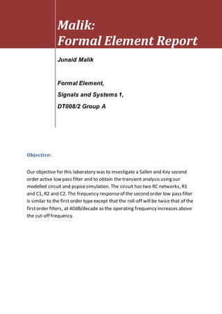
Our objective for this laboratory was to investigate a Sallen and Key second
order active low pass filter and to obtain the transient analysis using our
modelled circuit and pspicesimulation. The circuit has two RC networks, R1
and C1, R2 and C2. The frequency responseof the second order low pass filter
is similar to the first order type except that the roll-off will be twice that of the
firstorder filters, at 40dB/decade as the operating frequency increases above
the cut-off frequency.
Malik:
Formal Element Report
Junaid Malik
Formal Element,
Signals and Systems 1,
DT008/2 Group A
Circuit Design:
Figure 1 Simulation settings to obtain transient analysis
U1
uA741
+
3
-
2
V+
7
V-
4
OUT
6
OS1
1
OS2
5
R1
100k
R2
4.7k
R3
100k
R4
10k
C1
820p
C2
820p
V2
15Vdc
V3
15Vdc
0
0
neg
out
pos
neg
Junaid Malik, DT008/2, Group A, 6/11/12
V4
FREQ = 1.7k
VAMPL = 1
VOFF = 0
AC = 1
pos
VDB
Reference2
R1= 100k R2=100k C1= 820p C2 820p R4=4.7k R3=10k
Vin(s)→ →Vout(s)
Transfer Function
G(s)=
218619869.126
s2+18658.5365854s+148720999.405
Cut-off frequency
fc = 1940.91394015 (Hz)
Quality factor
Q = 0.653594771242
Figure 2: This was the layout which we followed while constructing the Sallen and Key Second-
order active. Reference Paul Tobin.
Figure 3: This is a good layout example reference Paul Tobin.
Deriving the equation:
An active low-pass filter is required to meet the following specification:
 The maximum passband loss Amax = 0.5dB
 The minimum stopband loss Amin = 12dB
 The passband edge frequency ωp = 100 rs−1( f p = ωp/2π = 15.9 Hz)
 The stopband edge frequency ωs = 400 rs−1
We had to obtain a Butterworth transfer function so that the Sallen and Key active
filter circuit could meet the required specification.
The filter order is calculated as follows =>
𝑛 =
log10 [
10(0.1𝑥𝐴𝑚𝑖𝑛)
− 1
10(0.1𝑥𝐴𝑚𝑎𝑥) − 1 ]
2𝑙𝑜𝑔10 (
𝑤𝑠
𝑤𝑝
)
𝑛 =
log10 [
10(0.1𝑥12)
− 1
10(0.1𝑥0.5) − 1 ]
2𝑙𝑜𝑔10 (
400
100
)
𝑛 =
log10[
14.8489
0.12207
]
2𝑙𝑜𝑔10(4)
𝑛 =
2.08529
1.204119
𝑛 = 1.731
𝑛 ≈ 2
𝑆𝑖𝑛𝑐𝑒 𝑤𝑒 𝑘𝑛𝑜𝑤 𝑡ℎ𝑎𝑡 𝑅𝑏 = 10𝑘Ω 𝑎𝑛𝑑 𝑅𝑎 = 4.7𝑘Ω
𝑘 = 1 +
𝑅𝑎
𝑅𝑏
= 1.47𝑘
𝐴𝑠𝑠𝑢𝑚𝑖𝑛𝑔 𝑡ℎ𝑎𝑡 𝑎 𝑣𝑎𝑙𝑢𝑒 𝑓𝑜𝑟 𝑅𝑏 = 10 𝑘 𝑎𝑛𝑑 𝑅𝑎
= 4.7 𝑘, 𝑡ℎ𝑒𝑟𝑒𝑓𝑜𝑟𝑒 𝑡ℎ𝑒 𝑔𝑎𝑖𝑛 𝑖𝑛 𝑑𝐵 𝑖𝑠
𝑘|𝑑𝐵 = 20 log(1.47) = 3.346 𝑑𝐵
𝑇ℎ𝑒 𝑙𝑜𝑤 𝑝𝑎𝑠𝑠 𝑓𝑖𝑙𝑡𝑒𝑟 𝑡𝑟𝑎𝑛𝑠𝑓𝑒𝑟 𝑓𝑢𝑛𝑐𝑡𝑖𝑜𝑛
𝑖𝑠 𝑜𝑏𝑡𝑎𝑖𝑛𝑒𝑑 𝑏𝑦 𝑎𝑝𝑝𝑙𝑦𝑖𝑛g 𝑡ℎ𝑒 𝑝𝑜𝑡𝑒𝑛𝑡𝑖𝑎𝑙 𝑑𝑖𝑣𝑖𝑑𝑒𝑟 𝑡𝑒𝑐ℎ𝑛𝑖𝑞𝑢𝑒.
𝑆𝑒𝑐𝑜𝑛𝑑 𝑜𝑟𝑑𝑒𝑟 ∶ $2
+ 1.414$ + 1
𝐻($) =
1
$2 + 1.414$+ 1
𝐻( 𝑠) =
1
(
𝑠
𝜔𝑐
)
2
+ 1.414(
𝑠
𝜔𝑐
)+ 1
=
𝜔𝑐2
𝑠2 + 1.414𝜔𝐶𝑠 + 𝜔𝑐2
𝑇𝑓 =
𝑉𝑜( 𝑠)
𝑉𝑖𝑛( 𝑠)
=
(
𝑘
𝐶2 𝑅2)
𝑠2 + (
3 − 𝑘
𝐶𝑅
) 𝑠 + (
1
𝐶2 𝑅2)
𝜔𝑐 =
1
𝐶𝑅
= 2𝜋𝑓𝑐 =
1
𝐶𝑅
= 𝑓𝑐 =
1
2𝜋𝐶𝑅
𝜔𝑐
𝑄
=
3 − 𝑘
𝐶𝑅
= 𝑄 =
1
3 − 𝑘
Results:
TableofResults
Frequency Vin Vout Vout/Vin 20log(vout/vin)
1Hz 1 1 0 0 dB
10Hz 1 1.390V 1.390V 2.86 dB
100Hz 1 1.405V 1.405V 2.95 dB
1000Hz 1 1.431V 1.431V 3.11 dB
1.2kHz 1 1.361V 1.361V 2.677 dB
1.6kHz 1 1.269V 1.269V 2.062 dB
1.8kHz 1 1.170V 1.170V 1.363 dB
2.0kHz 1 1.064V 1.064V 0.531 dB
2.2kHz 1 962.3mV 962.3mV -0.33 dB
2.4kHz 1 864mV 864mV -1.269 dB
2.6kHz 1 776.6mV 776.6mV -2.19 dB
2.8kHz 1 695.4mV 695.4mV -3.15 dB
3.0kHz 1 626.4mV 626.4mV -4.06 dB
From this table of results we can see that as the frequency is increased, the out
output voltage is reduced in effect.
Graph
First graphoffrequencyagainstvoltage
GRAPH 1: The frequency response above is the same as for a first order filter. The difference this
time is the steepness of the roll-off which is at -40dB/decade.
Secondgraphofvolatgeagainstfrequency
GRAPH 2:
Frequency
1.0Hz 3.0Hz 10Hz 30Hz 100Hz 300Hz 1.0KHz 3.0KHz 10KHz 30KHz 100KHz
DB(V(OUT))
-80
-60
-40
-20
-0
20
Junaid Malik, DT008/2, Group A
passband gain = 1 + ra/rb = 1.47
(23.806K,-40.2dB decade)
(3.1331K,-6.01dB Decade)
Frequency
1.0Hz 3.0Hz 10Hz 30Hz 100Hz 300Hz 1.0KHz 3.0KHz 10KHz 30KHz 100KHz
V(OUT)
0V
0.5V
1.0V
1.5V
Junaid Malik, DT008/2, Group A, 6/11/12
k = 1 +Ra/Rb=1.47k
(1v,1.47k)
Conclusion:
In conclusion there are many filter types and ways to implement them but an active low-
pass filter that’s greatly simplified if R1=R2 and the op amp stage is a unity gain follower
(RB=short and RA=open). The Sallen and Key filter attenuates any input signal in the
frequency range above the cut-off frequency to a point, but then the response turns around
and starts to increase in gain with frequency. The response in the stop band should keep
decreasing as the frequency increases. Instead, the response actually will begin rising again
at some high frequency. A properly functioning op amp is needed for the filters operation;
op amps lose voltage gain at some frequency because of their finite bandwidth.
References
Reference 1: Paul Tobin
Reference 2: http://sim.okawa-denshi.jp/en/OPstool.php
Reference 3: PSpice forFiltersandTransmissionLinesby Paul Tobin

More Related Content

What's hot

RF Module Design - [Chapter 8] Phase-Locked Loops
RF Module Design - [Chapter 8] Phase-Locked LoopsRF Module Design - [Chapter 8] Phase-Locked Loops
RF Module Design - [Chapter 8] Phase-Locked LoopsSimen Li
 
射頻電子 - [第六章] 低雜訊放大器設計
射頻電子 - [第六章] 低雜訊放大器設計射頻電子 - [第六章] 低雜訊放大器設計
射頻電子 - [第六章] 低雜訊放大器設計Simen Li
 
射頻電子 - [第三章] 史密斯圖與阻抗匹配
射頻電子 - [第三章] 史密斯圖與阻抗匹配射頻電子 - [第三章] 史密斯圖與阻抗匹配
射頻電子 - [第三章] 史密斯圖與阻抗匹配Simen Li
 
6 radar range-doppler-angular loops
6 radar range-doppler-angular loops6 radar range-doppler-angular loops
6 radar range-doppler-angular loopsSolo Hermelin
 
RF Module Design - [Chapter 3] Linearity
RF Module Design - [Chapter 3]  LinearityRF Module Design - [Chapter 3]  Linearity
RF Module Design - [Chapter 3] LinearitySimen Li
 
射頻電子 - [第四章] 散射參數網路
射頻電子 - [第四章] 散射參數網路射頻電子 - [第四章] 散射參數網路
射頻電子 - [第四章] 散射參數網路Simen Li
 
First order sigma delta modulator with low-power
First order sigma delta modulator with low-powerFirst order sigma delta modulator with low-power
First order sigma delta modulator with low-powereSAT Publishing House
 
電路學 - [第五章] 一階RC/RL電路
電路學 - [第五章] 一階RC/RL電路電路學 - [第五章] 一階RC/RL電路
電路學 - [第五章] 一階RC/RL電路Simen Li
 
Sigma Delta ADC for Implantable Cardiac Sensing
Sigma Delta ADC for Implantable Cardiac SensingSigma Delta ADC for Implantable Cardiac Sensing
Sigma Delta ADC for Implantable Cardiac SensingRamprasad Vijayagopal
 
射頻電子 - [第二章] 傳輸線理論
射頻電子 - [第二章] 傳輸線理論射頻電子 - [第二章] 傳輸線理論
射頻電子 - [第二章] 傳輸線理論Simen Li
 
Fiber optics ray theory
Fiber optics ray theoryFiber optics ray theory
Fiber optics ray theorySolo Hermelin
 
iCAT C600 Permanent Link Test with iCAT Cat6 Jack
iCAT C600 Permanent Link Test with iCAT Cat6 JackiCAT C600 Permanent Link Test with iCAT Cat6 Jack
iCAT C600 Permanent Link Test with iCAT Cat6 JackJulie Fletcher
 
電路學 - [第三章] 網路定理
電路學 - [第三章] 網路定理電路學 - [第三章] 網路定理
電路學 - [第三章] 網路定理Simen Li
 
Circuit Network Analysis - [Chapter3] Fourier Analysis
Circuit Network Analysis - [Chapter3] Fourier AnalysisCircuit Network Analysis - [Chapter3] Fourier Analysis
Circuit Network Analysis - [Chapter3] Fourier AnalysisSimen Li
 
Standing waves in the stairwell
Standing waves in the stairwellStanding waves in the stairwell
Standing waves in the stairwellAlexander Burt
 
TH1.L10.3: MONOSTATIC CALIBRATION OF BOTH TANDEM-X SATELLITES
TH1.L10.3: MONOSTATIC CALIBRATION OF BOTH TANDEM-X SATELLITESTH1.L10.3: MONOSTATIC CALIBRATION OF BOTH TANDEM-X SATELLITES
TH1.L10.3: MONOSTATIC CALIBRATION OF BOTH TANDEM-X SATELLITESgrssieee
 
Roll eccentricity compensation system for an aluminium rolling mill
Roll eccentricity compensation system for an aluminium rolling millRoll eccentricity compensation system for an aluminium rolling mill
Roll eccentricity compensation system for an aluminium rolling millIan Caister
 

What's hot (20)

RF Module Design - [Chapter 8] Phase-Locked Loops
RF Module Design - [Chapter 8] Phase-Locked LoopsRF Module Design - [Chapter 8] Phase-Locked Loops
RF Module Design - [Chapter 8] Phase-Locked Loops
 
射頻電子 - [第六章] 低雜訊放大器設計
射頻電子 - [第六章] 低雜訊放大器設計射頻電子 - [第六章] 低雜訊放大器設計
射頻電子 - [第六章] 低雜訊放大器設計
 
射頻電子 - [第三章] 史密斯圖與阻抗匹配
射頻電子 - [第三章] 史密斯圖與阻抗匹配射頻電子 - [第三章] 史密斯圖與阻抗匹配
射頻電子 - [第三章] 史密斯圖與阻抗匹配
 
6 radar range-doppler-angular loops
6 radar range-doppler-angular loops6 radar range-doppler-angular loops
6 radar range-doppler-angular loops
 
RF Module Design - [Chapter 3] Linearity
RF Module Design - [Chapter 3]  LinearityRF Module Design - [Chapter 3]  Linearity
RF Module Design - [Chapter 3] Linearity
 
射頻電子 - [第四章] 散射參數網路
射頻電子 - [第四章] 散射參數網路射頻電子 - [第四章] 散射參數網路
射頻電子 - [第四章] 散射參數網路
 
First order sigma delta modulator with low-power
First order sigma delta modulator with low-powerFirst order sigma delta modulator with low-power
First order sigma delta modulator with low-power
 
電路學 - [第五章] 一階RC/RL電路
電路學 - [第五章] 一階RC/RL電路電路學 - [第五章] 一階RC/RL電路
電路學 - [第五章] 一階RC/RL電路
 
Sigma Delta ADC for Implantable Cardiac Sensing
Sigma Delta ADC for Implantable Cardiac SensingSigma Delta ADC for Implantable Cardiac Sensing
Sigma Delta ADC for Implantable Cardiac Sensing
 
射頻電子 - [第二章] 傳輸線理論
射頻電子 - [第二章] 傳輸線理論射頻電子 - [第二章] 傳輸線理論
射頻電子 - [第二章] 傳輸線理論
 
Preparing PRF
Preparing PRFPreparing PRF
Preparing PRF
 
Fiber optics ray theory
Fiber optics ray theoryFiber optics ray theory
Fiber optics ray theory
 
3920 Assn_1
3920 Assn_13920 Assn_1
3920 Assn_1
 
iCAT C600 Permanent Link Test with iCAT Cat6 Jack
iCAT C600 Permanent Link Test with iCAT Cat6 JackiCAT C600 Permanent Link Test with iCAT Cat6 Jack
iCAT C600 Permanent Link Test with iCAT Cat6 Jack
 
電路學 - [第三章] 網路定理
電路學 - [第三章] 網路定理電路學 - [第三章] 網路定理
電路學 - [第三章] 網路定理
 
Circuit Network Analysis - [Chapter3] Fourier Analysis
Circuit Network Analysis - [Chapter3] Fourier AnalysisCircuit Network Analysis - [Chapter3] Fourier Analysis
Circuit Network Analysis - [Chapter3] Fourier Analysis
 
Chapter 7 1
Chapter 7 1Chapter 7 1
Chapter 7 1
 
Standing waves in the stairwell
Standing waves in the stairwellStanding waves in the stairwell
Standing waves in the stairwell
 
TH1.L10.3: MONOSTATIC CALIBRATION OF BOTH TANDEM-X SATELLITES
TH1.L10.3: MONOSTATIC CALIBRATION OF BOTH TANDEM-X SATELLITESTH1.L10.3: MONOSTATIC CALIBRATION OF BOTH TANDEM-X SATELLITES
TH1.L10.3: MONOSTATIC CALIBRATION OF BOTH TANDEM-X SATELLITES
 
Roll eccentricity compensation system for an aluminium rolling mill
Roll eccentricity compensation system for an aluminium rolling millRoll eccentricity compensation system for an aluminium rolling mill
Roll eccentricity compensation system for an aluminium rolling mill
 

Viewers also liked

AWSA Final Coaching Presentation 2016
AWSA Final Coaching Presentation 2016AWSA Final Coaching Presentation 2016
AWSA Final Coaching Presentation 2016Benjamin Eugenio
 
AcensNews Enero 2011
AcensNews Enero 2011AcensNews Enero 2011
AcensNews Enero 2011Acens
 
qaqc engineer piping NEW CV
qaqc engineer piping NEW CVqaqc engineer piping NEW CV
qaqc engineer piping NEW CVRajamohan mohan
 
Cadeira Secretária Havaii - cinza j serrano
Cadeira Secretária Havaii - cinza j serranoCadeira Secretária Havaii - cinza j serrano
Cadeira Secretária Havaii - cinza j serranoIndústria das Cadeiras
 
Moving trailers, truckingcube
Moving trailers, truckingcubeMoving trailers, truckingcube
Moving trailers, truckingcubeTruckingCube
 
ElipseAD Portfolio 2013 SP
ElipseAD Portfolio 2013 SPElipseAD Portfolio 2013 SP
ElipseAD Portfolio 2013 SPElipseAD
 
Nidos de luz DARÍO AUTRÁN
Nidos de luz  DARÍO AUTRÁNNidos de luz  DARÍO AUTRÁN
Nidos de luz DARÍO AUTRÁNAmayi Valencia
 
ieee final year projects in trichy .
ieee final year projects in trichy .ieee final year projects in trichy .
ieee final year projects in trichy .vsanthosh05
 
Interview bfmtv 1 @LuisColasante #LuisColasante Luis Colasante
Interview bfmtv 1 @LuisColasante #LuisColasante  Luis ColasanteInterview bfmtv 1 @LuisColasante #LuisColasante  Luis Colasante
Interview bfmtv 1 @LuisColasante #LuisColasante Luis ColasanteSogefi Group
 
ChristinaTrainhamoffcialTranscriptsept16
ChristinaTrainhamoffcialTranscriptsept16ChristinaTrainhamoffcialTranscriptsept16
ChristinaTrainhamoffcialTranscriptsept16Christina Trainham
 

Viewers also liked (14)

Powerengineering
PowerengineeringPowerengineering
Powerengineering
 
AWSA Final Coaching Presentation 2016
AWSA Final Coaching Presentation 2016AWSA Final Coaching Presentation 2016
AWSA Final Coaching Presentation 2016
 
AcensNews Enero 2011
AcensNews Enero 2011AcensNews Enero 2011
AcensNews Enero 2011
 
qaqc engineer piping NEW CV
qaqc engineer piping NEW CVqaqc engineer piping NEW CV
qaqc engineer piping NEW CV
 
EBS IT Software Institucional
EBS IT Software InstitucionalEBS IT Software Institucional
EBS IT Software Institucional
 
Objetos de Aprendizaje
Objetos de AprendizajeObjetos de Aprendizaje
Objetos de Aprendizaje
 
Cadeira Secretária Havaii - cinza j serrano
Cadeira Secretária Havaii - cinza j serranoCadeira Secretária Havaii - cinza j serrano
Cadeira Secretária Havaii - cinza j serrano
 
Moving trailers, truckingcube
Moving trailers, truckingcubeMoving trailers, truckingcube
Moving trailers, truckingcube
 
ElipseAD Portfolio 2013 SP
ElipseAD Portfolio 2013 SPElipseAD Portfolio 2013 SP
ElipseAD Portfolio 2013 SP
 
Changi Village Hotel
Changi Village HotelChangi Village Hotel
Changi Village Hotel
 
Nidos de luz DARÍO AUTRÁN
Nidos de luz  DARÍO AUTRÁNNidos de luz  DARÍO AUTRÁN
Nidos de luz DARÍO AUTRÁN
 
ieee final year projects in trichy .
ieee final year projects in trichy .ieee final year projects in trichy .
ieee final year projects in trichy .
 
Interview bfmtv 1 @LuisColasante #LuisColasante Luis Colasante
Interview bfmtv 1 @LuisColasante #LuisColasante  Luis ColasanteInterview bfmtv 1 @LuisColasante #LuisColasante  Luis Colasante
Interview bfmtv 1 @LuisColasante #LuisColasante Luis Colasante
 
ChristinaTrainhamoffcialTranscriptsept16
ChristinaTrainhamoffcialTranscriptsept16ChristinaTrainhamoffcialTranscriptsept16
ChristinaTrainhamoffcialTranscriptsept16
 

Similar to Sallen and Key Second Order Active Low Pass Filter Transient Analysis

First order active rc sections hw1
First order active rc sections hw1First order active rc sections hw1
First order active rc sections hw1Hoopeer Hoopeer
 
Variable frequencyresponseanalysis8ed
Variable frequencyresponseanalysis8edVariable frequencyresponseanalysis8ed
Variable frequencyresponseanalysis8edxebiikhan
 
Presentació renovables
Presentació renovablesPresentació renovables
Presentació renovablesJordi Cusido
 
Demonstrating Quantum Speed-Up with a Two-Transmon Quantum Processor Ph.D. d...
Demonstrating Quantum Speed-Up  with a Two-Transmon Quantum Processor Ph.D. d...Demonstrating Quantum Speed-Up  with a Two-Transmon Quantum Processor Ph.D. d...
Demonstrating Quantum Speed-Up with a Two-Transmon Quantum Processor Ph.D. d...Andreas Dewes
 
eecs242_lect3_rxarch.pdf
eecs242_lect3_rxarch.pdfeecs242_lect3_rxarch.pdf
eecs242_lect3_rxarch.pdfNahshonMObiri
 
Filters and Tuned Amplifiers
Filters and Tuned AmplifiersFilters and Tuned Amplifiers
Filters and Tuned Amplifiersselarothitc
 
Design and Analysis of Active Bandpass Filter
Design and Analysis of Active Bandpass FilterDesign and Analysis of Active Bandpass Filter
Design and Analysis of Active Bandpass FilterKyla Marino
 
HW3 – Nichols plots and frequency domain specifications FORM.docx
HW3 – Nichols plots and frequency domain specifications FORM.docxHW3 – Nichols plots and frequency domain specifications FORM.docx
HW3 – Nichols plots and frequency domain specifications FORM.docxsheronlewthwaite
 
Real 2nd order LC PLL loop analysis.pptx
Real 2nd order LC PLL loop analysis.pptxReal 2nd order LC PLL loop analysis.pptx
Real 2nd order LC PLL loop analysis.pptxSaiGouthamSunkara
 
Active Filter Design Using PSpice
Active Filter Design Using PSpiceActive Filter Design Using PSpice
Active Filter Design Using PSpiceTsuyoshi Horigome
 
4 matched filters and ambiguity functions for radar signals-2
4 matched filters and ambiguity functions for radar signals-24 matched filters and ambiguity functions for radar signals-2
4 matched filters and ambiguity functions for radar signals-2Solo Hermelin
 
RF Module Design - [Chapter 7] Voltage-Controlled Oscillator
RF Module Design - [Chapter 7] Voltage-Controlled OscillatorRF Module Design - [Chapter 7] Voltage-Controlled Oscillator
RF Module Design - [Chapter 7] Voltage-Controlled OscillatorSimen Li
 
Other RLC resonant circuits and Bode Plots 2024.pptx
Other RLC resonant circuits and Bode Plots 2024.pptxOther RLC resonant circuits and Bode Plots 2024.pptx
Other RLC resonant circuits and Bode Plots 2024.pptxDrOmarShAlyozbaky
 
UC Davis gyrotron cavity simulation
UC Davis gyrotron cavity simulationUC Davis gyrotron cavity simulation
UC Davis gyrotron cavity simulationPei-Che Chang
 

Similar to Sallen and Key Second Order Active Low Pass Filter Transient Analysis (20)

First order active rc sections hw1
First order active rc sections hw1First order active rc sections hw1
First order active rc sections hw1
 
Variable frequencyresponseanalysis8ed
Variable frequencyresponseanalysis8edVariable frequencyresponseanalysis8ed
Variable frequencyresponseanalysis8ed
 
Presentació renovables
Presentació renovablesPresentació renovables
Presentació renovables
 
Demonstrating Quantum Speed-Up with a Two-Transmon Quantum Processor Ph.D. d...
Demonstrating Quantum Speed-Up  with a Two-Transmon Quantum Processor Ph.D. d...Demonstrating Quantum Speed-Up  with a Two-Transmon Quantum Processor Ph.D. d...
Demonstrating Quantum Speed-Up with a Two-Transmon Quantum Processor Ph.D. d...
 
eecs242_lect3_rxarch.pdf
eecs242_lect3_rxarch.pdfeecs242_lect3_rxarch.pdf
eecs242_lect3_rxarch.pdf
 
Filter_Designs
Filter_DesignsFilter_Designs
Filter_Designs
 
Filters and Tuned Amplifiers
Filters and Tuned AmplifiersFilters and Tuned Amplifiers
Filters and Tuned Amplifiers
 
Design and Analysis of Active Bandpass Filter
Design and Analysis of Active Bandpass FilterDesign and Analysis of Active Bandpass Filter
Design and Analysis of Active Bandpass Filter
 
HW3 – Nichols plots and frequency domain specifications FORM.docx
HW3 – Nichols plots and frequency domain specifications FORM.docxHW3 – Nichols plots and frequency domain specifications FORM.docx
HW3 – Nichols plots and frequency domain specifications FORM.docx
 
14 activefilters
14 activefilters14 activefilters
14 activefilters
 
Real 2nd order LC PLL loop analysis.pptx
Real 2nd order LC PLL loop analysis.pptxReal 2nd order LC PLL loop analysis.pptx
Real 2nd order LC PLL loop analysis.pptx
 
Active Filter Design Using PSpice
Active Filter Design Using PSpiceActive Filter Design Using PSpice
Active Filter Design Using PSpice
 
4 matched filters and ambiguity functions for radar signals-2
4 matched filters and ambiguity functions for radar signals-24 matched filters and ambiguity functions for radar signals-2
4 matched filters and ambiguity functions for radar signals-2
 
RF Module Design - [Chapter 7] Voltage-Controlled Oscillator
RF Module Design - [Chapter 7] Voltage-Controlled OscillatorRF Module Design - [Chapter 7] Voltage-Controlled Oscillator
RF Module Design - [Chapter 7] Voltage-Controlled Oscillator
 
Other RLC resonant circuits and Bode Plots 2024.pptx
Other RLC resonant circuits and Bode Plots 2024.pptxOther RLC resonant circuits and Bode Plots 2024.pptx
Other RLC resonant circuits and Bode Plots 2024.pptx
 
Ad7716
Ad7716Ad7716
Ad7716
 
DSP.ppt
DSP.pptDSP.ppt
DSP.ppt
 
13486500-FFT.ppt
13486500-FFT.ppt13486500-FFT.ppt
13486500-FFT.ppt
 
UC Davis gyrotron cavity simulation
UC Davis gyrotron cavity simulationUC Davis gyrotron cavity simulation
UC Davis gyrotron cavity simulation
 
STAN Tool overview
STAN Tool overviewSTAN Tool overview
STAN Tool overview
 

Sallen and Key Second Order Active Low Pass Filter Transient Analysis

  • 1. Objective: Our objective for this laboratory was to investigate a Sallen and Key second order active low pass filter and to obtain the transient analysis using our modelled circuit and pspicesimulation. The circuit has two RC networks, R1 and C1, R2 and C2. The frequency responseof the second order low pass filter is similar to the first order type except that the roll-off will be twice that of the firstorder filters, at 40dB/decade as the operating frequency increases above the cut-off frequency. Malik: Formal Element Report Junaid Malik Formal Element, Signals and Systems 1, DT008/2 Group A
  • 2. Circuit Design: Figure 1 Simulation settings to obtain transient analysis U1 uA741 + 3 - 2 V+ 7 V- 4 OUT 6 OS1 1 OS2 5 R1 100k R2 4.7k R3 100k R4 10k C1 820p C2 820p V2 15Vdc V3 15Vdc 0 0 neg out pos neg Junaid Malik, DT008/2, Group A, 6/11/12 V4 FREQ = 1.7k VAMPL = 1 VOFF = 0 AC = 1 pos VDB
  • 3. Reference2 R1= 100k R2=100k C1= 820p C2 820p R4=4.7k R3=10k Vin(s)→ →Vout(s) Transfer Function G(s)= 218619869.126 s2+18658.5365854s+148720999.405 Cut-off frequency fc = 1940.91394015 (Hz) Quality factor Q = 0.653594771242
  • 4. Figure 2: This was the layout which we followed while constructing the Sallen and Key Second- order active. Reference Paul Tobin.
  • 5. Figure 3: This is a good layout example reference Paul Tobin.
  • 6. Deriving the equation: An active low-pass filter is required to meet the following specification:  The maximum passband loss Amax = 0.5dB  The minimum stopband loss Amin = 12dB  The passband edge frequency ωp = 100 rs−1( f p = ωp/2π = 15.9 Hz)  The stopband edge frequency ωs = 400 rs−1 We had to obtain a Butterworth transfer function so that the Sallen and Key active filter circuit could meet the required specification. The filter order is calculated as follows => 𝑛 = log10 [ 10(0.1𝑥𝐴𝑚𝑖𝑛) − 1 10(0.1𝑥𝐴𝑚𝑎𝑥) − 1 ] 2𝑙𝑜𝑔10 ( 𝑤𝑠 𝑤𝑝 ) 𝑛 = log10 [ 10(0.1𝑥12) − 1 10(0.1𝑥0.5) − 1 ] 2𝑙𝑜𝑔10 ( 400 100 ) 𝑛 = log10[ 14.8489 0.12207 ] 2𝑙𝑜𝑔10(4) 𝑛 = 2.08529 1.204119 𝑛 = 1.731 𝑛 ≈ 2
  • 7. 𝑆𝑖𝑛𝑐𝑒 𝑤𝑒 𝑘𝑛𝑜𝑤 𝑡ℎ𝑎𝑡 𝑅𝑏 = 10𝑘Ω 𝑎𝑛𝑑 𝑅𝑎 = 4.7𝑘Ω 𝑘 = 1 + 𝑅𝑎 𝑅𝑏 = 1.47𝑘 𝐴𝑠𝑠𝑢𝑚𝑖𝑛𝑔 𝑡ℎ𝑎𝑡 𝑎 𝑣𝑎𝑙𝑢𝑒 𝑓𝑜𝑟 𝑅𝑏 = 10 𝑘 𝑎𝑛𝑑 𝑅𝑎 = 4.7 𝑘, 𝑡ℎ𝑒𝑟𝑒𝑓𝑜𝑟𝑒 𝑡ℎ𝑒 𝑔𝑎𝑖𝑛 𝑖𝑛 𝑑𝐵 𝑖𝑠 𝑘|𝑑𝐵 = 20 log(1.47) = 3.346 𝑑𝐵 𝑇ℎ𝑒 𝑙𝑜𝑤 𝑝𝑎𝑠𝑠 𝑓𝑖𝑙𝑡𝑒𝑟 𝑡𝑟𝑎𝑛𝑠𝑓𝑒𝑟 𝑓𝑢𝑛𝑐𝑡𝑖𝑜𝑛 𝑖𝑠 𝑜𝑏𝑡𝑎𝑖𝑛𝑒𝑑 𝑏𝑦 𝑎𝑝𝑝𝑙𝑦𝑖𝑛g 𝑡ℎ𝑒 𝑝𝑜𝑡𝑒𝑛𝑡𝑖𝑎𝑙 𝑑𝑖𝑣𝑖𝑑𝑒𝑟 𝑡𝑒𝑐ℎ𝑛𝑖𝑞𝑢𝑒. 𝑆𝑒𝑐𝑜𝑛𝑑 𝑜𝑟𝑑𝑒𝑟 ∶ $2 + 1.414$ + 1 𝐻($) = 1 $2 + 1.414$+ 1 𝐻( 𝑠) = 1 ( 𝑠 𝜔𝑐 ) 2 + 1.414( 𝑠 𝜔𝑐 )+ 1 = 𝜔𝑐2 𝑠2 + 1.414𝜔𝐶𝑠 + 𝜔𝑐2 𝑇𝑓 = 𝑉𝑜( 𝑠) 𝑉𝑖𝑛( 𝑠) = ( 𝑘 𝐶2 𝑅2) 𝑠2 + ( 3 − 𝑘 𝐶𝑅 ) 𝑠 + ( 1 𝐶2 𝑅2) 𝜔𝑐 = 1 𝐶𝑅 = 2𝜋𝑓𝑐 = 1 𝐶𝑅 = 𝑓𝑐 = 1 2𝜋𝐶𝑅 𝜔𝑐 𝑄 = 3 − 𝑘 𝐶𝑅 = 𝑄 = 1 3 − 𝑘
  • 8. Results: TableofResults Frequency Vin Vout Vout/Vin 20log(vout/vin) 1Hz 1 1 0 0 dB 10Hz 1 1.390V 1.390V 2.86 dB 100Hz 1 1.405V 1.405V 2.95 dB 1000Hz 1 1.431V 1.431V 3.11 dB 1.2kHz 1 1.361V 1.361V 2.677 dB 1.6kHz 1 1.269V 1.269V 2.062 dB 1.8kHz 1 1.170V 1.170V 1.363 dB 2.0kHz 1 1.064V 1.064V 0.531 dB 2.2kHz 1 962.3mV 962.3mV -0.33 dB 2.4kHz 1 864mV 864mV -1.269 dB 2.6kHz 1 776.6mV 776.6mV -2.19 dB 2.8kHz 1 695.4mV 695.4mV -3.15 dB 3.0kHz 1 626.4mV 626.4mV -4.06 dB From this table of results we can see that as the frequency is increased, the out output voltage is reduced in effect.
  • 9. Graph First graphoffrequencyagainstvoltage GRAPH 1: The frequency response above is the same as for a first order filter. The difference this time is the steepness of the roll-off which is at -40dB/decade. Secondgraphofvolatgeagainstfrequency GRAPH 2: Frequency 1.0Hz 3.0Hz 10Hz 30Hz 100Hz 300Hz 1.0KHz 3.0KHz 10KHz 30KHz 100KHz DB(V(OUT)) -80 -60 -40 -20 -0 20 Junaid Malik, DT008/2, Group A passband gain = 1 + ra/rb = 1.47 (23.806K,-40.2dB decade) (3.1331K,-6.01dB Decade) Frequency 1.0Hz 3.0Hz 10Hz 30Hz 100Hz 300Hz 1.0KHz 3.0KHz 10KHz 30KHz 100KHz V(OUT) 0V 0.5V 1.0V 1.5V Junaid Malik, DT008/2, Group A, 6/11/12 k = 1 +Ra/Rb=1.47k (1v,1.47k)
  • 10. Conclusion: In conclusion there are many filter types and ways to implement them but an active low- pass filter that’s greatly simplified if R1=R2 and the op amp stage is a unity gain follower (RB=short and RA=open). The Sallen and Key filter attenuates any input signal in the frequency range above the cut-off frequency to a point, but then the response turns around and starts to increase in gain with frequency. The response in the stop band should keep decreasing as the frequency increases. Instead, the response actually will begin rising again at some high frequency. A properly functioning op amp is needed for the filters operation; op amps lose voltage gain at some frequency because of their finite bandwidth.
  • 11. References Reference 1: Paul Tobin Reference 2: http://sim.okawa-denshi.jp/en/OPstool.php Reference 3: PSpice forFiltersandTransmissionLinesby Paul Tobin