SlideShare a Scribd company logo
1 of 13
Download to read offline
DRAFT INSPECTION PLAN Page 1 of 13
I = Inspection T = Testing Not Applicable
S. No
SYSTEM – SUBSYSTEM
CIVIL WORKS
FREQUENCY OF INSPECTIONS / TESTS LOCATION
PRE-PROCESS IN-PROCESS POST-PROCESS PRECAST YARD IN - SITU SOURCE
1. PRECAST YARDS
1.1. TYPICAL PRECAST YARD
1.1.1. Materials Storage Areas I I I X X
1.1.2. Batching Plant I I I X
1.1.3. Ice Plant I I I X
1.1.4. Laboratory Tests (Throughout Product. Process) I – T I – T I - T X X
1.1.5. Molds I I I X X
1.1.6. Rebar Works I I I X X
1.1.7. Assembly I I I X
1.1.8. Concreting I – T I – T I X X
1.1.9. Storage I I I X
1.1.10. Stripping I I I X
1.1.11. Quarantine Area I I I X
1.1.12. Storage I I I X
1.1.13. Release to Site I I I X
2. BATCHING PLANTS
2.1. TYPICAL BATCHING PLANT
2.1.1. Aggregate I – T I – T
2.1.2. Water Absorption I – T I – T
2.1.3. Scales I – T I – T
2.1.4. Water Meters I – T I – T
2.1.5. Admixture Dispensers I – T I – T
2.1.6. Mixing Equipment and Agitators I – T I – T
DRAFT INSPECTION PLAN Page 2 of 13
I = Inspection T = Testing Not Applicable
S. No
SYSTEM – SUBSYSTEM
CIVIL WORKS
INSPECTIONS / TESTS LOCATION
PRE-PROCESS IN-PROCESS POST-PROCESS PRECAST YARD IN - SITU SOURCE
3. TRACKS (63.44 Km) L1 = 38.06 Km L2 = 25.38 Km
3.1. SEGMENTALLY LINED (16.19 Km)
3.1.1. Site Surveys I – T I – T I X
3.1.2. Line and Level I I I X
3.1.3. Ring Build Profile I I I X
3.1.4. Bolt Installation I I I X
3.1.5. Grout Installation (Pressure/Volume/Strength) I I I X
3.1.6. Surface Monitoring I I I X
3.1.7. Excavation Volume/Weight I I I X
3.1.8. TBM Drive Parameters I I I X
3.1.9. Utilities I I I X X
3.1.10. Emergency Exits I I I X
3.2. NATM
3.2.1. Concrete Strength Gain I – T I – T I – T X
3.2.2. Geotechnical Logging/Face Stability I I X
3.2.3. Surface Monitoring I I I X
3.2.4. Convergence Monitoring I I I X
3.2.5. Line and Level I I I X
3.2.6. Excavation Profile I I I X
3.2.7. Spray Depth I I X
3.2.8. Dewatering Flow/Level (If Required) I I I X
3.2.9. Excavation Advance Length I I X
3.2.10. Reinforcement Spacing I X
3.2.11. Joint Preparation I I X
3.2.12. Utilities I I I X X
3.2.13. Emergency Exits I I I X
DRAFT INSPECTION PLAN Page 3 of 13
I = Inspection T = Testing Not Applicable
S. No
SYSTEM – SUBSYSTEM
CIVIL WORKS
FREQUENCY OF INSPECTIONS / TESTS LOCATION
PRE-PROCESS IN-PROCESS POST-PROCESS PRECAST YARD IN - SITU SOURCE
3.3. ELEVATED VIADUCTS (18.5 Km) L1 = 14.12 Km L2 = 4.38 Km
3.3.1. Site Surveys I - T X
3.3.2. FOUNDATIONS
3.3.2.1. Earth Works I - T I - T I - T X X
3.3.2.2. False Work I I I X X
3.3.2.3. Concrete Works I - T I - T I - T X X
3.3.3. COLUMNS
3.3.3.1. Material Request I I X X
3.3.3.2. Positioning of Prefabricated Components I I I X
3.3.3.3. Balance Cantilever I I I X X
3.3.3.4. Post-tensioning I I I - T X
3.3.4. VIADUCT SEGMENTS (PREFABRICATED)
3.3.4.1. Material Request I I X X
3.3.4.2. Positioning of Segments I I I X X
3.3.4.3. Final Posttensioning I I I - T X
3.3.5. T-BEAMS
3.3.6. Material Request I – T I – T I - T X
3.3.7. Pre-tensioning I I I X
3.3.8. Transportation to Site I I I X X
3.3.9. Positioning I I I - T X
3.4. AT GRADE TRACKS (18.04 Km) L1 = 3.50 Km L2 = 14.53 Km
3.4.1. Site Surveys I – T
3.4.2. Earthworks I – T I – T I – T
3.4.3. False Work I I I
3.4.4. Concrete Work I – T I – T I – T
3.4.5. Utilities I I I
DRAFT INSPECTION PLAN Page 4 of 13
I = Inspection T = Testing Not Applicable
S. No
SYSTEM – SUBSYSTEM
CIVIL WORKS
FREQUENCY OF INSPECTIONS / TESTS LOCATION
PRE-PROCESS IN-PROCESS POST-PROCESS PRECAST YARD IN - SITU SOURCE
3.5. OPEN CUT TUNNEL (1.67 Km) L1 = 0.47 Km L2 = 1.2 Km
3.5.1. Site Surveys I – T
3.5.2. Earthworks I – T I – T I – T
3.5.3. False Work I I I
3.5.4. Concrete Work I – T I – T I – T
3.5.5. Utilities I I I
3.6. CUT & COVER TUNNEL (0.73 Km) L1 = 0.28 Km L2 = 0.45 Km
3.6.1. Site Surveys I – T
3.6.2. Earthworks I – T I – T I – T
3.6.3. False Work I I I
3.6.4. Concrete Work I – T I – T I – T
3.6.5. Utilities I I I
3.7. TRANSITION RAMPS (2.49 Km) L1 = 2.03 Km L2 = 0.46 Km
3.7.1. Site Surveys I – T
3.7.2. Earthworks I – T I – T I – T
3.7.3. False Work I I I
3.7.4. Concrete Work I – T I – T I – T
3.7.5. Utilities I I I
3.8. STATIONS (5.83 Km) L1 = 3.64 Km L2 = 2.19 Km
3.8.1. Site Surveys I – T
3.8.2. Earthworks I – T I – T I – T
3.8.3. False Work I I I
3.8.4. Concrete Work I – T I – T I – T
3.8.5. Utilities I I I
DRAFT INSPECTION PLAN Page 5 of 13
I = Inspection T = Testing Not Applicable
S. No
SYSTEM – SUBSYSTEM
CIVIL WORKS
FREQUENCY OF INSPECTIONS / TESTS LOCATION
PRE-PROCESS IN-PROCESS POST-PROCESS PRECAST YARD IN - SITU SOURCE
4. STATIONS L1 = 26 L2 = 15 L1 + L2 = 41
4.1. ELEVATED (11) L1 = 8 L2 = 3 L1 = L2 = 11
4.1.1. Site Surveys I – T I - T I X
4.1.2. Concrete Works I I - T I X X
4.1.3. Steel Works I I I X X
4.1.4. Roofing I I I X X
4.1.5. Flooring & Ceilings I I I X X
4.1.6. Partitions I I I X X
4.1.7. Stairs I I I X
4.1.8. Escalators I I I – T X X
4.1.9. Glass Works I I I X X
4.1.10. Windows & Doors I I I X X
4.1.11. Emergency Exits I I I X
4.1.12. Water Systems (Water & Sanitary) I I I – T X X
4.1.13. HVAC I I I – T X X
4.1.14. Electrical Network I I I – T X X
4.1.15. Lighting Systems I I I – T X X
4.1.16. Fire Protection & Fire Fighting I I I – T X X
4.1.17. Drainage System I I I – T X
4.1.18. Telecommunications I I I – T X X
4.1.19. Public Address System I I I – T X X
4.1.20. Internal & External Finishings I I I X X
4.1.21. Ticketing Hall I I I X X
4.1.22. Platform Screen Doors I I I – T X X
4.1.23. Platforms (Embarking – Disembarking Areas) I I I X
4.1.24. Train Track Area I I I X
4.1.25. Emergency Power Generation (Station) I I I – T X X
DRAFT INSPECTION PLAN Page 6 of 13
I = Inspection T = Testing Not Applicable
S. No
SYSTEM – SUBSYSTEM
CIVIL WORKS
FREQUENCY OF INSPECTIONS / TESTS LOCATION
PRE-PROCESS IN-PROCESS POST-PROCESS PRECAST YARD IN - SITU SOURCE
4. STATIONS L1 = 26 L2 = 15 L1 + L2 = 41
4.2. AT GRADE STATIONS (3) L1 = 0 L2 = 3 L1 + L2 = 3
4.2.1. Site Surveys I – T I – T I X
4.2.2. Concrete Works I I – T I X X
4.2.3. Steel Works I I I X X
4.2.4. Roofing I I I X X
4.2.5. Flooring & Ceilings I I I X X
4.2.6. Partitions I I I X X
4.2.7. Stairs I I I X
4.2.8. Escalators I I I – T X X
4.2.9. Glass Works I I I X X
4.2.10. Windows & Doors I I I X X
4.2.11. Emergency Exits I I I X
4.2.12. Water Systems (Water & Sanitary) I I I – T X X
4.2.13. HVAC I I I – T X X
4.2.14. Electrical Network I I I – T X X
4.2.15. Lighting Systems I I I – T X X
4.2.16. Fire Protection & Fire Fighting I I I – T X X
4.2.17. Drainage System I I I – T X
4.2.18. Telecommunications I I I – T X X
4.2.19. Public Address System I I I – T X X
4.2.20. Internal & External Finishings I I I X X
4.2.21. Ticketing Hall I I I X X
4.2.22. Platform Screen Doors I I I – T X X
4.2.23. Platforms (Embarking – Disembarking Areas) I I I X
4.2.24. Train Track Area I I I X
4.2.25. Emergency Power Generation (Station) I I I – T X X
DRAFT INSPECTION PLAN Page 7 of 13
I = Inspection T = Testing Not Applicable
S. No
SYSTEM – SUBSYSTEM
CIVIL WORKS
FREQUENCY OF INSPECTIONS / TESTS LOCATION
PRE-PROCESS IN-PROCESS POST-PROCESS PRECAST YARD IN - SITU SOURCE
4. STATIONS L1 = 26 L2 = 15 L1 + L2 = 41
4.3. DEEP UNDERGROUND L1 = 14 L2 = 1 L1 + L2 = 15
4.3.1. Site Surveys I – T I – T I X
4.3.2. Concrete Works I I – T I X X
4.3.3. Steel Works I I I X X
4.3.4. Roofing I I I X X
4.3.5. Flooring & Ceilings I I I X X
4.3.6. Partitions I I I X X
4.3.7. Stairs I I I X
4.3.8. Escalators I I I – T X X
4.3.9. Glass Works I I I X X
4.3.10. Windows & Doors I I I X X
4.3.11. Emergency Exits I I I X
4.3.12. Water Systems (Water & Sanitary) I I I – T X X
4.3.13. HVAC I I I – T X X
4.3.14. Electrical Network I I I – T X X
4.3.15. Lighting Systems I I I – T X X
4.3.16. Fire Protection & Fire Fighting I I I – T X X
4.3.17. Drainage System I I I – T X
4.3.18. Telecommunications I I I – T X X
4.3.19. Public Address System I I I – T X X
4.3.20. Internal & External Finishings I I I X X
4.3.21. Ticketing Hall I I I X X
4.3.22. Platform Screen Doors I I I – T X X
4.3.23. Platforms (Embarking – Disembarking Areas) I I I X
4.3.24. Train Track Area & Tunnel Interfaces I I I X
4.3.25. Emergency Power Generation (Station) I I I – T X X
DRAFT INSPECTION PLAN Page 8 of 13
I = Inspection T = Testing Not Applicable
S. No
SYSTEM – SUBSYSTEM
CIVIL WORKS
FREQUENCY OF INSPECTIONS / TESTS LOCATION
PRE-PROCESS IN-PROCESS POST-PROCESS PRECAST YARD IN - SITU SOURCE
4. STATIONS L1 = 26 L2 = 15 L1 + L2 = 41
4.4. SHALLOW UNDERGROUND L1 = 0 L2 = 6 L1 + L2 = 6
4.4.1. Site Surveys I – T I – T I X
4.4.2. Concrete Works I I – T I X X
4.4.3. Steel Works I I I X X
4.4.4. Roofing I I I X X
4.4.5. Flooring & Ceilings I I I X X
4.4.6. Partitions I I I X X
4.4.7. Stairs I I I X
4.4.8. Escalators I I I – T X X
4.4.9. Glass Works I I I X X
4.4.10. Windows & Doors I I I X X
4.4.11. Emergency Exits I I I X
4.4.12. Water Systems (Water & Sanitary) I I I – T X X
4.4.13. HVAC I I I – T X X
4.4.14. Electrical Network I I I – T X X
4.4.15. Lighting Systems I I I – T X X
4.4.16. Fire Protection & Fire Fighting I I I – T X X
4.4.17. Drainage System I I I – T X
4.4.18. Telecommunications I I I – T X X
4.4.19. Public Address System I I I – T X X
4.4.20. Internal & External Finishings I I I X X
4.4.21. Ticketing Hall I I I X X
4.4.22. Platform Screen Doors I I I – T X X
4.4.23. Platforms (Embarking – Disembarking Areas) I I I X
4.4.24. Train Track Area & Tunnel Interfaces I I I X
4.4.25. Emergency Power Generation (Station) I I I – T X X
DRAFT INSPECTION PLAN Page 9 of 13
I = Inspection T = Testing Not Applicable
S. No
SYSTEM – SUBSYSTEM
CIVIL WORKS
FREQUENCY OF INSPECTIONS / TESTS LOCATION
PRE-PROCESS IN-PROCESS POST-PROCESS PRECAST YARD IN - SITU SOURCE
4. STATIONS L1 = 26 L2 = 15 L1 + L2 = 41
4.5. TRANSFER STATIONS L1 = 4 L2 = 2 L1 + L2 = 6
4.5.1. Site Surveys I – T I – T I X
4.5.2. Concrete Works I I – T I X X
4.5.3. Steel Works I I I X X
4.5.4. Roofing I I I X X
4.5.5. Flooring & Ceilings I I I X X
4.5.6. Partitions I I I X X
4.5.7. Stairs I I I X
4.5.8. Escalators I I I – T X X
4.5.9. Glass Works I I I X X
4.5.10. Windows & Doors I I I X X
4.5.11. Emergency Exits I I I X
4.5.12. Water Systems (Water & Sanitary) I I I – T X X
4.5.13. HVAC I I I – T X X
4.5.14. Electrical Network I I I – T X X
4.5.15. Lighting Systems I I I – T X X
4.5.16. Fire Protection & Fire Fighting I I I – T X X
4.5.17. Drainage System I I I – T X
4.5.18. Telecommunications I I I – T X X
4.5.19. Public Address System I I I – T X X
4.5.20. Internal & External Finishings I I I X X
4.5.21. Ticketing Hall I I I X X
4.5.22. Platform Screen Doors I I I – T X X
4.5.23. Platforms (Embarking – Disembarking Areas) I I I X
4.5.24. Train Track Area & Tunnel Interfaces (2 levels) I I I X
4.5.25. Emergency Power Generation (Station) I I I – T X X
DRAFT INSPECTION PLAN Page 10 of 13
I = Inspection T = Testing Not Applicable
S. No
SYSTEM – SUBSYSTEM
CIVIL WORKS
FREQUENCY OF INSPECTIONS / TESTS LOCATION
PRE-PROCESS IN-PROCESS POST-PROCESS PRECAST YARD IN - SITU SOURCE
5. OTHER STRUCTURES
5.1. DEPOTS & STABLING L1 = 2 L2 = 1 L1 + L2 = 3
5.1.1. Site Surveys I – T I – T I X
5.1.2. Concrete Works I I – T I X X
5.1.3. Steel Works I I I X X
5.1.4. Roofing I I I X X
5.1.5. Flooring & Ceilings I I I X X
5.1.6. Partitions I I I X X
5.1.7. Stairs I I I X
5.1.8. Glass Works I I I X X
5.1.9. Windows & Doors I I I X X
5.1.10. Emergency Exits I I I X
5.1.11. Water Systems (Water & Sanitary) I I I – T X X
5.1.12. HVAC I I I – T X X
5.1.13. Electrical Network I I I – T X X
5.1.14. Lighting Systems I I I – T X X
5.1.15. Fire Protection & Fire Fighting I I I – T X X
5.1.16. Drainage System I I I – T X
5.1.17. Telecommunications I I I – T X X
5.1.18. Public Address System I I I – T X X
5.1.19. Internal & External Finishings I I I X X
5.1.20. Train Track Area I I I X
5.1.21. Emergency Power Generation Systems I I I – T X X
5.1.22. Maintenance Areas I I I X
5.1.23. Maintenance Equipment I I I X X
5.1.24. Train Wash Building I I I X X
5.1.25. Parking Areas & Landscaping I I – T I – T X
DRAFT INSPECTION PLAN Page 11 of 13
I = Inspection T = Testing Not Applicable
S. No
SYSTEM – SUBSYSTEM
CIVIL WORKS
FREQUENCY OF INSPECTIONS / TESTS LOCATION
PRE-PROCESS IN-PROCESS POST-PROCESS PRECAST YARD IN - SITU SOURCE
5.2. STABLINGS ONLY L1 = 0 L2 = 1 L1 + L2 = 1
5.2.1. Site Surveys I I – T I X
5.2.2. Concrete Works I I – T I X
5.2.3. Steel Works I I I X X
5.2.4. Roofing I I I X X
5.2.5. Flooring & Ceilings I I I X X
5.2.6. Partitions I I I X X
5.2.7. Stairs I I I X
5.2.8. Glass Works I I I X X
5.2.9. Windows & Doors I I I X X
5.2.10. Emergency Exits I I I X
5.2.11. Water Systems (Water & Sanitary) I I I – T X X
5.2.12. HVAC I I I – T X X
5.2.13. Electrical Network I I I – T X X
5.2.14. Lighting Systems I I I – T X X
5.2.15. Fire Protection & Fire Fighting I I I – T X X
5.2.16. Drainage System I I I – T X
5.2.17. Telecommunications I I I – T X X
5.2.18. Public Address System I I I – T X X
5.2.19. Internal & External Finishings I I I X X
5.2.20. Train Track Area I I I X
5.2.21. Emergency Power Generation Systems I I I – T X X
5.2.22. Parking Areas - Roads & Landscaping I I – T I – T X X
DRAFT INSPECTION PLAN Page 12 of 13
I = Inspection T = Testing Not Applicable
S. No
SYSTEM – SUBSYSTEM
CIVIL WORKS
FREQUENCY OF INSPECTIONS / TESTS LOCATION
PRE-PROCESS IN-PROCESS POST-PROCESS PRECAST YARD IN - SITU SOURCE
5.3. PARK & RIDE L1 = 3 L2 = 2 L1 + L2 = 5
5.3.1. Site Surveys I I – T I X
5.3.2. Earth Works I I – T I X X
5.3.3. Concrete Works I I – T I X X
5.3.4. Asphalt Works I I – T I X X
5.3.5. Canopies I I I X X
5.3.6. Lighting I I I X X
5.3.7. Security Booths I I I X X
5.3.8. Operations Booth I I I X X
5.3.9. Ticketing System I I I X X
S. No
SYSTEM – SUBSYSTEM
CIVIL WORKS
FREQUENCY OF INSPECTIONS / TESTS LOCATION
PRE-PROCESS IN-PROCESS POST-PROCESS PRECAST YARD IN - SITU SOURCE
6. ROADS
6.1.1. Site Surveys I I – T I X
6.1.2. Earth Works I I – T I X X
6.1.3. Sub Base I I – T I X X
6.1.4. Sub Grade I I – T I X X
6.1.5. Concreting I I – T I X X
6.1.6. Asphalting I I – T I X X
6.1.7. Lighting I I I X X
6.1.8. Power Distribution I I I X X
DRAFT INSPECTION PLAN Page 13 of 13
I = Inspection T = Testing Not Applicable
S. No
SYSTEM – SUBSYSTEM
ROLLING STOCK
FREQUENCY OF INSPECTIONS / TESTS LOCATION
PRE-PROCESS IN-PROCESS POST-PROCESS PRECAST YARD IN - SITU SOURCE
7. TRANSIT SYSTEM
7.1. POWER TRACK SYSTEM
7.1.1.
Will be populated after the Performance
Validation Matrix has been developed as per the
requirements of the System Validation Plan
reference M-BAC-000000-GE00-MPL-00001
7.1.2.
7.1.3.
7.1.4.
7.1.5.
7.2. OPERATION & CONTROL SYSTEM
7.2.1.
Will be populated after the Performance
Validation Matrix has been developed as per the
requirements of the System Validation Plan
reference M-BAC-000000-GE00-MPL-00001
7.2.2.
7.2.3.
7.2.4.
7.2.5.
7.3. ROLLING STOCK
7.3.1.
Will be populated after the Performance
Validation Matrix has been developed as per the
requirements of the System Validation Plan
reference M-BAC-000000-GE00-MPL-00001
7.3.2.
7.3.3.
7.3.4.
7.3.5.

More Related Content

What's hot

Régulation de niveau, identification du procédé, exercice AZprocede
Régulation de niveau, identification du procédé, exercice AZprocedeRégulation de niveau, identification du procédé, exercice AZprocede
Régulation de niveau, identification du procédé, exercice AZprocedeNicolas JOUVE
 
00-2STE-Complet_2021-2022.pdf
00-2STE-Complet_2021-2022.pdf00-2STE-Complet_2021-2022.pdf
00-2STE-Complet_2021-2022.pdfTouriyaMoukhles
 
Rapport stage : Mise en place d’un plan de maintenance
Rapport stage : Mise en place d’un plan de maintenanceRapport stage : Mise en place d’un plan de maintenance
Rapport stage : Mise en place d’un plan de maintenanceYounesSALEK1
 
Les risques du batiment
Les risques du batimentLes risques du batiment
Les risques du batimentSami Sahli
 
Cours fabrication mécanique1
Cours fabrication mécanique1Cours fabrication mécanique1
Cours fabrication mécanique1bendrisk
 
11 analyse-deffaillance-compresseur-ingersoll-rand-ssr-ml-15
11 analyse-deffaillance-compresseur-ingersoll-rand-ssr-ml-1511 analyse-deffaillance-compresseur-ingersoll-rand-ssr-ml-15
11 analyse-deffaillance-compresseur-ingersoll-rand-ssr-ml-15jaouadgindus
 
Diagnostique des installations frigorifiques 2022 helali ahmed
Diagnostique  des installations frigorifiques 2022 helali ahmedDiagnostique  des installations frigorifiques 2022 helali ahmed
Diagnostique des installations frigorifiques 2022 helali ahmedAhmed Helali
 
Chapitre ii architecture interne des processeurs
Chapitre ii architecture interne des processeursChapitre ii architecture interne des processeurs
Chapitre ii architecture interne des processeursSana Aroussi
 
Rapport de stage PFE ( DUT) chez Synthèse Conseil - Jaiti Mohammed
Rapport de stage PFE ( DUT) chez Synthèse Conseil  - Jaiti MohammedRapport de stage PFE ( DUT) chez Synthèse Conseil  - Jaiti Mohammed
Rapport de stage PFE ( DUT) chez Synthèse Conseil - Jaiti MohammedMohammed JAITI
 
Annex 14 2018 Volume 1(8th edition).pdf
Annex 14 2018 Volume 1(8th edition).pdfAnnex 14 2018 Volume 1(8th edition).pdf
Annex 14 2018 Volume 1(8th edition).pdfYasmine Anino
 
Microcontroleur Pic16 F84
Microcontroleur Pic16 F84Microcontroleur Pic16 F84
Microcontroleur Pic16 F84guest1e7b02
 
Compte rendu de tp de commande numerique
Compte rendu de tp de commande numeriqueCompte rendu de tp de commande numerique
Compte rendu de tp de commande numeriqueELMEHDYELWARDY
 

What's hot (20)

Stage sonatrach
Stage sonatrachStage sonatrach
Stage sonatrach
 
Régulation de niveau, identification du procédé, exercice AZprocede
Régulation de niveau, identification du procédé, exercice AZprocedeRégulation de niveau, identification du procédé, exercice AZprocede
Régulation de niveau, identification du procédé, exercice AZprocede
 
00-2STE-Complet_2021-2022.pdf
00-2STE-Complet_2021-2022.pdf00-2STE-Complet_2021-2022.pdf
00-2STE-Complet_2021-2022.pdf
 
Rapport stage : Mise en place d’un plan de maintenance
Rapport stage : Mise en place d’un plan de maintenanceRapport stage : Mise en place d’un plan de maintenance
Rapport stage : Mise en place d’un plan de maintenance
 
Modele rapport pfe esprit
Modele rapport pfe  espritModele rapport pfe  esprit
Modele rapport pfe esprit
 
05 gamme
05 gamme05 gamme
05 gamme
 
Les risques du batiment
Les risques du batimentLes risques du batiment
Les risques du batiment
 
Cours fabrication mécanique1
Cours fabrication mécanique1Cours fabrication mécanique1
Cours fabrication mécanique1
 
Cahier Meca 4 ST Part 1/2
Cahier Meca 4 ST Part 1/2Cahier Meca 4 ST Part 1/2
Cahier Meca 4 ST Part 1/2
 
11 analyse-deffaillance-compresseur-ingersoll-rand-ssr-ml-15
11 analyse-deffaillance-compresseur-ingersoll-rand-ssr-ml-1511 analyse-deffaillance-compresseur-ingersoll-rand-ssr-ml-15
11 analyse-deffaillance-compresseur-ingersoll-rand-ssr-ml-15
 
Rapport
RapportRapport
Rapport
 
Diagnostique des installations frigorifiques 2022 helali ahmed
Diagnostique  des installations frigorifiques 2022 helali ahmedDiagnostique  des installations frigorifiques 2022 helali ahmed
Diagnostique des installations frigorifiques 2022 helali ahmed
 
Chapitre ii architecture interne des processeurs
Chapitre ii architecture interne des processeursChapitre ii architecture interne des processeurs
Chapitre ii architecture interne des processeurs
 
Rapport de stage PFE ( DUT) chez Synthèse Conseil - Jaiti Mohammed
Rapport de stage PFE ( DUT) chez Synthèse Conseil  - Jaiti MohammedRapport de stage PFE ( DUT) chez Synthèse Conseil  - Jaiti Mohammed
Rapport de stage PFE ( DUT) chez Synthèse Conseil - Jaiti Mohammed
 
1exer dessin
1exer dessin1exer dessin
1exer dessin
 
Cahier Meca 4 ST Part 2/2
Cahier Meca 4 ST Part 2/2Cahier Meca 4 ST Part 2/2
Cahier Meca 4 ST Part 2/2
 
Cahier Meca 4 ST Part 1/2
Cahier Meca 4 ST Part 1/2Cahier Meca 4 ST Part 1/2
Cahier Meca 4 ST Part 1/2
 
Annex 14 2018 Volume 1(8th edition).pdf
Annex 14 2018 Volume 1(8th edition).pdfAnnex 14 2018 Volume 1(8th edition).pdf
Annex 14 2018 Volume 1(8th edition).pdf
 
Microcontroleur Pic16 F84
Microcontroleur Pic16 F84Microcontroleur Pic16 F84
Microcontroleur Pic16 F84
 
Compte rendu de tp de commande numerique
Compte rendu de tp de commande numeriqueCompte rendu de tp de commande numerique
Compte rendu de tp de commande numerique
 

Viewers also liked

Smoke Damper Presentantion
Smoke Damper PresentantionSmoke Damper Presentantion
Smoke Damper Presentantionchrishvaceng
 
Fire Hydrant System : Secured Engineers
Fire Hydrant System : Secured EngineersFire Hydrant System : Secured Engineers
Fire Hydrant System : Secured Engineerssecuredengineers
 
Jaikaran Dan ( Testing and Commissioning Engineer )
Jaikaran Dan ( Testing and Commissioning Engineer  ) Jaikaran Dan ( Testing and Commissioning Engineer  )
Jaikaran Dan ( Testing and Commissioning Engineer ) jaikaran dan
 
Fire protection system, inspection and test
Fire protection system, inspection and testFire protection system, inspection and test
Fire protection system, inspection and testAngkut Roongsaengjan
 
Inspection, Testing and Maintenance of fire pump
Inspection, Testing and Maintenance of fire pumpInspection, Testing and Maintenance of fire pump
Inspection, Testing and Maintenance of fire pumpklsmani
 
fire detection and alarm system
fire detection and alarm systemfire detection and alarm system
fire detection and alarm systemsingh1515
 
Materi pelatihan hydrant 1
Materi pelatihan hydrant 1Materi pelatihan hydrant 1
Materi pelatihan hydrant 1Eko Kiswanto
 
Sistem Pemadam Api dan Pengindera Api
Sistem Pemadam Api dan Pengindera ApiSistem Pemadam Api dan Pengindera Api
Sistem Pemadam Api dan Pengindera ApiIwanSukirman
 
Fire Detection and Alarm Systems
Fire Detection and Alarm SystemsFire Detection and Alarm Systems
Fire Detection and Alarm SystemsJ.T.A.JONES
 
Fire Protection Systems Unit-I
Fire Protection Systems Unit-IFire Protection Systems Unit-I
Fire Protection Systems Unit-IGAURAV. H .TANDON
 

Viewers also liked (18)

Chapter 7
Chapter 7Chapter 7
Chapter 7
 
Chapter 05
Chapter 05Chapter 05
Chapter 05
 
Chapter 07
Chapter 07Chapter 07
Chapter 07
 
Smoke Damper Presentantion
Smoke Damper PresentantionSmoke Damper Presentantion
Smoke Damper Presentantion
 
Fire Hydrant System : Secured Engineers
Fire Hydrant System : Secured EngineersFire Hydrant System : Secured Engineers
Fire Hydrant System : Secured Engineers
 
Smoke detector
Smoke detectorSmoke detector
Smoke detector
 
Dampers
DampersDampers
Dampers
 
Jaikaran Dan ( Testing and Commissioning Engineer )
Jaikaran Dan ( Testing and Commissioning Engineer  ) Jaikaran Dan ( Testing and Commissioning Engineer  )
Jaikaran Dan ( Testing and Commissioning Engineer )
 
Fire protection system, inspection and test
Fire protection system, inspection and testFire protection system, inspection and test
Fire protection system, inspection and test
 
Inspection, Testing and Maintenance of fire pump
Inspection, Testing and Maintenance of fire pumpInspection, Testing and Maintenance of fire pump
Inspection, Testing and Maintenance of fire pump
 
Modul K3
Modul K3Modul K3
Modul K3
 
Sprinkler system
Sprinkler systemSprinkler system
Sprinkler system
 
fire detection and alarm system
fire detection and alarm systemfire detection and alarm system
fire detection and alarm system
 
Materi pelatihan hydrant 1
Materi pelatihan hydrant 1Materi pelatihan hydrant 1
Materi pelatihan hydrant 1
 
Perancangan dan pemasangan sistem sprinkler pada gedung perkantoran
Perancangan dan pemasangan sistem sprinkler pada gedung perkantoranPerancangan dan pemasangan sistem sprinkler pada gedung perkantoran
Perancangan dan pemasangan sistem sprinkler pada gedung perkantoran
 
Sistem Pemadam Api dan Pengindera Api
Sistem Pemadam Api dan Pengindera ApiSistem Pemadam Api dan Pengindera Api
Sistem Pemadam Api dan Pengindera Api
 
Fire Detection and Alarm Systems
Fire Detection and Alarm SystemsFire Detection and Alarm Systems
Fire Detection and Alarm Systems
 
Fire Protection Systems Unit-I
Fire Protection Systems Unit-IFire Protection Systems Unit-I
Fire Protection Systems Unit-I
 

Draft Inspection Matrix.Rev.03

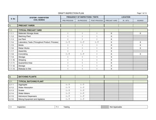
  • 1. DRAFT INSPECTION PLAN Page 1 of 13 I = Inspection T = Testing Not Applicable S. No SYSTEM – SUBSYSTEM CIVIL WORKS FREQUENCY OF INSPECTIONS / TESTS LOCATION PRE-PROCESS IN-PROCESS POST-PROCESS PRECAST YARD IN - SITU SOURCE 1. PRECAST YARDS 1.1. TYPICAL PRECAST YARD 1.1.1. Materials Storage Areas I I I X X 1.1.2. Batching Plant I I I X 1.1.3. Ice Plant I I I X 1.1.4. Laboratory Tests (Throughout Product. Process) I – T I – T I - T X X 1.1.5. Molds I I I X X 1.1.6. Rebar Works I I I X X 1.1.7. Assembly I I I X 1.1.8. Concreting I – T I – T I X X 1.1.9. Storage I I I X 1.1.10. Stripping I I I X 1.1.11. Quarantine Area I I I X 1.1.12. Storage I I I X 1.1.13. Release to Site I I I X 2. BATCHING PLANTS 2.1. TYPICAL BATCHING PLANT 2.1.1. Aggregate I – T I – T 2.1.2. Water Absorption I – T I – T 2.1.3. Scales I – T I – T 2.1.4. Water Meters I – T I – T 2.1.5. Admixture Dispensers I – T I – T 2.1.6. Mixing Equipment and Agitators I – T I – T
  • 2. DRAFT INSPECTION PLAN Page 2 of 13 I = Inspection T = Testing Not Applicable S. No SYSTEM – SUBSYSTEM CIVIL WORKS INSPECTIONS / TESTS LOCATION PRE-PROCESS IN-PROCESS POST-PROCESS PRECAST YARD IN - SITU SOURCE 3. TRACKS (63.44 Km) L1 = 38.06 Km L2 = 25.38 Km 3.1. SEGMENTALLY LINED (16.19 Km) 3.1.1. Site Surveys I – T I – T I X 3.1.2. Line and Level I I I X 3.1.3. Ring Build Profile I I I X 3.1.4. Bolt Installation I I I X 3.1.5. Grout Installation (Pressure/Volume/Strength) I I I X 3.1.6. Surface Monitoring I I I X 3.1.7. Excavation Volume/Weight I I I X 3.1.8. TBM Drive Parameters I I I X 3.1.9. Utilities I I I X X 3.1.10. Emergency Exits I I I X 3.2. NATM 3.2.1. Concrete Strength Gain I – T I – T I – T X 3.2.2. Geotechnical Logging/Face Stability I I X 3.2.3. Surface Monitoring I I I X 3.2.4. Convergence Monitoring I I I X 3.2.5. Line and Level I I I X 3.2.6. Excavation Profile I I I X 3.2.7. Spray Depth I I X 3.2.8. Dewatering Flow/Level (If Required) I I I X 3.2.9. Excavation Advance Length I I X 3.2.10. Reinforcement Spacing I X 3.2.11. Joint Preparation I I X 3.2.12. Utilities I I I X X 3.2.13. Emergency Exits I I I X
  • 3. DRAFT INSPECTION PLAN Page 3 of 13 I = Inspection T = Testing Not Applicable S. No SYSTEM – SUBSYSTEM CIVIL WORKS FREQUENCY OF INSPECTIONS / TESTS LOCATION PRE-PROCESS IN-PROCESS POST-PROCESS PRECAST YARD IN - SITU SOURCE 3.3. ELEVATED VIADUCTS (18.5 Km) L1 = 14.12 Km L2 = 4.38 Km 3.3.1. Site Surveys I - T X 3.3.2. FOUNDATIONS 3.3.2.1. Earth Works I - T I - T I - T X X 3.3.2.2. False Work I I I X X 3.3.2.3. Concrete Works I - T I - T I - T X X 3.3.3. COLUMNS 3.3.3.1. Material Request I I X X 3.3.3.2. Positioning of Prefabricated Components I I I X 3.3.3.3. Balance Cantilever I I I X X 3.3.3.4. Post-tensioning I I I - T X 3.3.4. VIADUCT SEGMENTS (PREFABRICATED) 3.3.4.1. Material Request I I X X 3.3.4.2. Positioning of Segments I I I X X 3.3.4.3. Final Posttensioning I I I - T X 3.3.5. T-BEAMS 3.3.6. Material Request I – T I – T I - T X 3.3.7. Pre-tensioning I I I X 3.3.8. Transportation to Site I I I X X 3.3.9. Positioning I I I - T X 3.4. AT GRADE TRACKS (18.04 Km) L1 = 3.50 Km L2 = 14.53 Km 3.4.1. Site Surveys I – T 3.4.2. Earthworks I – T I – T I – T 3.4.3. False Work I I I 3.4.4. Concrete Work I – T I – T I – T 3.4.5. Utilities I I I
  • 4. DRAFT INSPECTION PLAN Page 4 of 13 I = Inspection T = Testing Not Applicable S. No SYSTEM – SUBSYSTEM CIVIL WORKS FREQUENCY OF INSPECTIONS / TESTS LOCATION PRE-PROCESS IN-PROCESS POST-PROCESS PRECAST YARD IN - SITU SOURCE 3.5. OPEN CUT TUNNEL (1.67 Km) L1 = 0.47 Km L2 = 1.2 Km 3.5.1. Site Surveys I – T 3.5.2. Earthworks I – T I – T I – T 3.5.3. False Work I I I 3.5.4. Concrete Work I – T I – T I – T 3.5.5. Utilities I I I 3.6. CUT & COVER TUNNEL (0.73 Km) L1 = 0.28 Km L2 = 0.45 Km 3.6.1. Site Surveys I – T 3.6.2. Earthworks I – T I – T I – T 3.6.3. False Work I I I 3.6.4. Concrete Work I – T I – T I – T 3.6.5. Utilities I I I 3.7. TRANSITION RAMPS (2.49 Km) L1 = 2.03 Km L2 = 0.46 Km 3.7.1. Site Surveys I – T 3.7.2. Earthworks I – T I – T I – T 3.7.3. False Work I I I 3.7.4. Concrete Work I – T I – T I – T 3.7.5. Utilities I I I 3.8. STATIONS (5.83 Km) L1 = 3.64 Km L2 = 2.19 Km 3.8.1. Site Surveys I – T 3.8.2. Earthworks I – T I – T I – T 3.8.3. False Work I I I 3.8.4. Concrete Work I – T I – T I – T 3.8.5. Utilities I I I
  • 5. DRAFT INSPECTION PLAN Page 5 of 13 I = Inspection T = Testing Not Applicable S. No SYSTEM – SUBSYSTEM CIVIL WORKS FREQUENCY OF INSPECTIONS / TESTS LOCATION PRE-PROCESS IN-PROCESS POST-PROCESS PRECAST YARD IN - SITU SOURCE 4. STATIONS L1 = 26 L2 = 15 L1 + L2 = 41 4.1. ELEVATED (11) L1 = 8 L2 = 3 L1 = L2 = 11 4.1.1. Site Surveys I – T I - T I X 4.1.2. Concrete Works I I - T I X X 4.1.3. Steel Works I I I X X 4.1.4. Roofing I I I X X 4.1.5. Flooring & Ceilings I I I X X 4.1.6. Partitions I I I X X 4.1.7. Stairs I I I X 4.1.8. Escalators I I I – T X X 4.1.9. Glass Works I I I X X 4.1.10. Windows & Doors I I I X X 4.1.11. Emergency Exits I I I X 4.1.12. Water Systems (Water & Sanitary) I I I – T X X 4.1.13. HVAC I I I – T X X 4.1.14. Electrical Network I I I – T X X 4.1.15. Lighting Systems I I I – T X X 4.1.16. Fire Protection & Fire Fighting I I I – T X X 4.1.17. Drainage System I I I – T X 4.1.18. Telecommunications I I I – T X X 4.1.19. Public Address System I I I – T X X 4.1.20. Internal & External Finishings I I I X X 4.1.21. Ticketing Hall I I I X X 4.1.22. Platform Screen Doors I I I – T X X 4.1.23. Platforms (Embarking – Disembarking Areas) I I I X 4.1.24. Train Track Area I I I X 4.1.25. Emergency Power Generation (Station) I I I – T X X
  • 6. DRAFT INSPECTION PLAN Page 6 of 13 I = Inspection T = Testing Not Applicable S. No SYSTEM – SUBSYSTEM CIVIL WORKS FREQUENCY OF INSPECTIONS / TESTS LOCATION PRE-PROCESS IN-PROCESS POST-PROCESS PRECAST YARD IN - SITU SOURCE 4. STATIONS L1 = 26 L2 = 15 L1 + L2 = 41 4.2. AT GRADE STATIONS (3) L1 = 0 L2 = 3 L1 + L2 = 3 4.2.1. Site Surveys I – T I – T I X 4.2.2. Concrete Works I I – T I X X 4.2.3. Steel Works I I I X X 4.2.4. Roofing I I I X X 4.2.5. Flooring & Ceilings I I I X X 4.2.6. Partitions I I I X X 4.2.7. Stairs I I I X 4.2.8. Escalators I I I – T X X 4.2.9. Glass Works I I I X X 4.2.10. Windows & Doors I I I X X 4.2.11. Emergency Exits I I I X 4.2.12. Water Systems (Water & Sanitary) I I I – T X X 4.2.13. HVAC I I I – T X X 4.2.14. Electrical Network I I I – T X X 4.2.15. Lighting Systems I I I – T X X 4.2.16. Fire Protection & Fire Fighting I I I – T X X 4.2.17. Drainage System I I I – T X 4.2.18. Telecommunications I I I – T X X 4.2.19. Public Address System I I I – T X X 4.2.20. Internal & External Finishings I I I X X 4.2.21. Ticketing Hall I I I X X 4.2.22. Platform Screen Doors I I I – T X X 4.2.23. Platforms (Embarking – Disembarking Areas) I I I X 4.2.24. Train Track Area I I I X 4.2.25. Emergency Power Generation (Station) I I I – T X X
  • 7. DRAFT INSPECTION PLAN Page 7 of 13 I = Inspection T = Testing Not Applicable S. No SYSTEM – SUBSYSTEM CIVIL WORKS FREQUENCY OF INSPECTIONS / TESTS LOCATION PRE-PROCESS IN-PROCESS POST-PROCESS PRECAST YARD IN - SITU SOURCE 4. STATIONS L1 = 26 L2 = 15 L1 + L2 = 41 4.3. DEEP UNDERGROUND L1 = 14 L2 = 1 L1 + L2 = 15 4.3.1. Site Surveys I – T I – T I X 4.3.2. Concrete Works I I – T I X X 4.3.3. Steel Works I I I X X 4.3.4. Roofing I I I X X 4.3.5. Flooring & Ceilings I I I X X 4.3.6. Partitions I I I X X 4.3.7. Stairs I I I X 4.3.8. Escalators I I I – T X X 4.3.9. Glass Works I I I X X 4.3.10. Windows & Doors I I I X X 4.3.11. Emergency Exits I I I X 4.3.12. Water Systems (Water & Sanitary) I I I – T X X 4.3.13. HVAC I I I – T X X 4.3.14. Electrical Network I I I – T X X 4.3.15. Lighting Systems I I I – T X X 4.3.16. Fire Protection & Fire Fighting I I I – T X X 4.3.17. Drainage System I I I – T X 4.3.18. Telecommunications I I I – T X X 4.3.19. Public Address System I I I – T X X 4.3.20. Internal & External Finishings I I I X X 4.3.21. Ticketing Hall I I I X X 4.3.22. Platform Screen Doors I I I – T X X 4.3.23. Platforms (Embarking – Disembarking Areas) I I I X 4.3.24. Train Track Area & Tunnel Interfaces I I I X 4.3.25. Emergency Power Generation (Station) I I I – T X X
  • 8. DRAFT INSPECTION PLAN Page 8 of 13 I = Inspection T = Testing Not Applicable S. No SYSTEM – SUBSYSTEM CIVIL WORKS FREQUENCY OF INSPECTIONS / TESTS LOCATION PRE-PROCESS IN-PROCESS POST-PROCESS PRECAST YARD IN - SITU SOURCE 4. STATIONS L1 = 26 L2 = 15 L1 + L2 = 41 4.4. SHALLOW UNDERGROUND L1 = 0 L2 = 6 L1 + L2 = 6 4.4.1. Site Surveys I – T I – T I X 4.4.2. Concrete Works I I – T I X X 4.4.3. Steel Works I I I X X 4.4.4. Roofing I I I X X 4.4.5. Flooring & Ceilings I I I X X 4.4.6. Partitions I I I X X 4.4.7. Stairs I I I X 4.4.8. Escalators I I I – T X X 4.4.9. Glass Works I I I X X 4.4.10. Windows & Doors I I I X X 4.4.11. Emergency Exits I I I X 4.4.12. Water Systems (Water & Sanitary) I I I – T X X 4.4.13. HVAC I I I – T X X 4.4.14. Electrical Network I I I – T X X 4.4.15. Lighting Systems I I I – T X X 4.4.16. Fire Protection & Fire Fighting I I I – T X X 4.4.17. Drainage System I I I – T X 4.4.18. Telecommunications I I I – T X X 4.4.19. Public Address System I I I – T X X 4.4.20. Internal & External Finishings I I I X X 4.4.21. Ticketing Hall I I I X X 4.4.22. Platform Screen Doors I I I – T X X 4.4.23. Platforms (Embarking – Disembarking Areas) I I I X 4.4.24. Train Track Area & Tunnel Interfaces I I I X 4.4.25. Emergency Power Generation (Station) I I I – T X X
  • 9. DRAFT INSPECTION PLAN Page 9 of 13 I = Inspection T = Testing Not Applicable S. No SYSTEM – SUBSYSTEM CIVIL WORKS FREQUENCY OF INSPECTIONS / TESTS LOCATION PRE-PROCESS IN-PROCESS POST-PROCESS PRECAST YARD IN - SITU SOURCE 4. STATIONS L1 = 26 L2 = 15 L1 + L2 = 41 4.5. TRANSFER STATIONS L1 = 4 L2 = 2 L1 + L2 = 6 4.5.1. Site Surveys I – T I – T I X 4.5.2. Concrete Works I I – T I X X 4.5.3. Steel Works I I I X X 4.5.4. Roofing I I I X X 4.5.5. Flooring & Ceilings I I I X X 4.5.6. Partitions I I I X X 4.5.7. Stairs I I I X 4.5.8. Escalators I I I – T X X 4.5.9. Glass Works I I I X X 4.5.10. Windows & Doors I I I X X 4.5.11. Emergency Exits I I I X 4.5.12. Water Systems (Water & Sanitary) I I I – T X X 4.5.13. HVAC I I I – T X X 4.5.14. Electrical Network I I I – T X X 4.5.15. Lighting Systems I I I – T X X 4.5.16. Fire Protection & Fire Fighting I I I – T X X 4.5.17. Drainage System I I I – T X 4.5.18. Telecommunications I I I – T X X 4.5.19. Public Address System I I I – T X X 4.5.20. Internal & External Finishings I I I X X 4.5.21. Ticketing Hall I I I X X 4.5.22. Platform Screen Doors I I I – T X X 4.5.23. Platforms (Embarking – Disembarking Areas) I I I X 4.5.24. Train Track Area & Tunnel Interfaces (2 levels) I I I X 4.5.25. Emergency Power Generation (Station) I I I – T X X
  • 10. DRAFT INSPECTION PLAN Page 10 of 13 I = Inspection T = Testing Not Applicable S. No SYSTEM – SUBSYSTEM CIVIL WORKS FREQUENCY OF INSPECTIONS / TESTS LOCATION PRE-PROCESS IN-PROCESS POST-PROCESS PRECAST YARD IN - SITU SOURCE 5. OTHER STRUCTURES 5.1. DEPOTS & STABLING L1 = 2 L2 = 1 L1 + L2 = 3 5.1.1. Site Surveys I – T I – T I X 5.1.2. Concrete Works I I – T I X X 5.1.3. Steel Works I I I X X 5.1.4. Roofing I I I X X 5.1.5. Flooring & Ceilings I I I X X 5.1.6. Partitions I I I X X 5.1.7. Stairs I I I X 5.1.8. Glass Works I I I X X 5.1.9. Windows & Doors I I I X X 5.1.10. Emergency Exits I I I X 5.1.11. Water Systems (Water & Sanitary) I I I – T X X 5.1.12. HVAC I I I – T X X 5.1.13. Electrical Network I I I – T X X 5.1.14. Lighting Systems I I I – T X X 5.1.15. Fire Protection & Fire Fighting I I I – T X X 5.1.16. Drainage System I I I – T X 5.1.17. Telecommunications I I I – T X X 5.1.18. Public Address System I I I – T X X 5.1.19. Internal & External Finishings I I I X X 5.1.20. Train Track Area I I I X 5.1.21. Emergency Power Generation Systems I I I – T X X 5.1.22. Maintenance Areas I I I X 5.1.23. Maintenance Equipment I I I X X 5.1.24. Train Wash Building I I I X X 5.1.25. Parking Areas & Landscaping I I – T I – T X
  • 11. DRAFT INSPECTION PLAN Page 11 of 13 I = Inspection T = Testing Not Applicable S. No SYSTEM – SUBSYSTEM CIVIL WORKS FREQUENCY OF INSPECTIONS / TESTS LOCATION PRE-PROCESS IN-PROCESS POST-PROCESS PRECAST YARD IN - SITU SOURCE 5.2. STABLINGS ONLY L1 = 0 L2 = 1 L1 + L2 = 1 5.2.1. Site Surveys I I – T I X 5.2.2. Concrete Works I I – T I X 5.2.3. Steel Works I I I X X 5.2.4. Roofing I I I X X 5.2.5. Flooring & Ceilings I I I X X 5.2.6. Partitions I I I X X 5.2.7. Stairs I I I X 5.2.8. Glass Works I I I X X 5.2.9. Windows & Doors I I I X X 5.2.10. Emergency Exits I I I X 5.2.11. Water Systems (Water & Sanitary) I I I – T X X 5.2.12. HVAC I I I – T X X 5.2.13. Electrical Network I I I – T X X 5.2.14. Lighting Systems I I I – T X X 5.2.15. Fire Protection & Fire Fighting I I I – T X X 5.2.16. Drainage System I I I – T X 5.2.17. Telecommunications I I I – T X X 5.2.18. Public Address System I I I – T X X 5.2.19. Internal & External Finishings I I I X X 5.2.20. Train Track Area I I I X 5.2.21. Emergency Power Generation Systems I I I – T X X 5.2.22. Parking Areas - Roads & Landscaping I I – T I – T X X
  • 12. DRAFT INSPECTION PLAN Page 12 of 13 I = Inspection T = Testing Not Applicable S. No SYSTEM – SUBSYSTEM CIVIL WORKS FREQUENCY OF INSPECTIONS / TESTS LOCATION PRE-PROCESS IN-PROCESS POST-PROCESS PRECAST YARD IN - SITU SOURCE 5.3. PARK & RIDE L1 = 3 L2 = 2 L1 + L2 = 5 5.3.1. Site Surveys I I – T I X 5.3.2. Earth Works I I – T I X X 5.3.3. Concrete Works I I – T I X X 5.3.4. Asphalt Works I I – T I X X 5.3.5. Canopies I I I X X 5.3.6. Lighting I I I X X 5.3.7. Security Booths I I I X X 5.3.8. Operations Booth I I I X X 5.3.9. Ticketing System I I I X X S. No SYSTEM – SUBSYSTEM CIVIL WORKS FREQUENCY OF INSPECTIONS / TESTS LOCATION PRE-PROCESS IN-PROCESS POST-PROCESS PRECAST YARD IN - SITU SOURCE 6. ROADS 6.1.1. Site Surveys I I – T I X 6.1.2. Earth Works I I – T I X X 6.1.3. Sub Base I I – T I X X 6.1.4. Sub Grade I I – T I X X 6.1.5. Concreting I I – T I X X 6.1.6. Asphalting I I – T I X X 6.1.7. Lighting I I I X X 6.1.8. Power Distribution I I I X X
  • 13. DRAFT INSPECTION PLAN Page 13 of 13 I = Inspection T = Testing Not Applicable S. No SYSTEM – SUBSYSTEM ROLLING STOCK FREQUENCY OF INSPECTIONS / TESTS LOCATION PRE-PROCESS IN-PROCESS POST-PROCESS PRECAST YARD IN - SITU SOURCE 7. TRANSIT SYSTEM 7.1. POWER TRACK SYSTEM 7.1.1. Will be populated after the Performance Validation Matrix has been developed as per the requirements of the System Validation Plan reference M-BAC-000000-GE00-MPL-00001 7.1.2. 7.1.3. 7.1.4. 7.1.5. 7.2. OPERATION & CONTROL SYSTEM 7.2.1. Will be populated after the Performance Validation Matrix has been developed as per the requirements of the System Validation Plan reference M-BAC-000000-GE00-MPL-00001 7.2.2. 7.2.3. 7.2.4. 7.2.5. 7.3. ROLLING STOCK 7.3.1. Will be populated after the Performance Validation Matrix has been developed as per the requirements of the System Validation Plan reference M-BAC-000000-GE00-MPL-00001 7.3.2. 7.3.3. 7.3.4. 7.3.5.