Development of engineering geology in western united states
1596-1 N Olmstead Ph I Archaeology
1. REPORT TRACKING SHEET
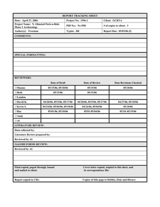
Date: April 27, 2006 Project No: 1596-1 Client: GCRTA
Project Name: N. Olmsted Park-n-Ride
Phase I Archaeology
PID No.: No PID # of copies to client: 3
Author(s): Freeman Typist: Jill Report Due: 05/03/06 (f)
COMMENTS:
SPECIAL FORMATTING:
REVIEWERS:
Date of Draft Date of Review Date Revisions Checked
☼Shaune 05/15/06, 05/18/06 05/15/06 05/18/06
☼Beth 05/15/06 05/15/06
☼Landon
☼David K. 04/20/06, 05/5/06, 05/17/06 04/20/06, 05/5/06, 05/17/06 04/27/06, 05/18/06
☼Kevin S. 04/24/06, 05/04/06, 05/18/06 04/24/06, 05/04/06 05/18/06
☼Rae 05/01/06, 05/18/06 05/01-05/04/06 05/18–05/19/06
☼Andy
☼Al
LITERATURE REVIEW:
Data collected by:
Literature Review prepared by:
Reviewed by Al:
OAI/OHI FORMS REVIEW:
Reviewed by Al:
Final copied, paged through, bound Cover letter copied, stapled to this sheet, and
and mailed to client: in correspondence file:
Report copied to CDs: Copies of title page to Debbie, Elsie and library:
2. Phase I Archaeological Survey of the Greater Cleveland
Regional Transit Authority Park-n-Ride Facility
Expansion in North Olmsted, Olmsted Township,
Cuyahoga County, Ohio
By
Jeremy B. Freeman
3. 2006-1596-1 N. Olmsted Phase I Archaeology
Phase I Archaeological Survey of the Greater Cleveland Regional Transit Authority
Park-n-Ride Facility Expansion in North Olmsted, Olmsted Township,
Cuyahoga County, Ohio
By
Jeremy B. Freeman
Submitted By:
Kevin Schwarz, Ph.D., RPA
Project Manager
ASC Group, Inc.
4620 Indianola Avenue
Columbus, Ohio 43214
(614) 268-2514
Submitted To:
Greater Cleveland Regional Transportation Authority
1240 West 6th Street
Cleveland, Ohio 44113-1331
(216) 566-5100
Lead Agency: ODOT
May 19, 2006
Printed on Recycled Paper
4. ABSTRACT
In response to the proposed expansion of a Greater Cleveland Regional Transit Authority
Park-n-Ride facility in North Olmsted, ASC Group, Inc., conducted a Phase I survey
reconnaissance in the area of potential effect. The project area is located across the street from
the current facility on Kennedy Ridge Road. The project area comprises a triangular section
located between Kennedy Ridge Road, Great Northern Boulevard, and I-480 in North Olmsted,
Olmsted Township, Cuyahoga County, Ohio. The area comprises 0.95 acres (0.39 ha) of land
and will add approximately 150 additional parking spaces for the current facility. The project is
being funded by the Ohio Department of Transportation (ODOT) with the use of Federal
Highway Administration (FHWA) funding. This necessitated that an archaeological survey be
conducted under Section 106 of the National Historic Preservation Act of 1966.
The project area previously contained two buildings. One building was of twentieth
century construction and one of mid-nineteenth-century construction. These buildings were
demolished in 2003. The nineteenth-century house was built ca. 1831–1840 by John Kennedy
and exhibited a combination of Greek Revival and Federal styles; it was later occupied by his
son, G. W. Kennedy.
Shovel test pits (STPs) were excavated across the project area at 32.8-ft (10-m) intervals.
STPs were excavated 3.9 in (10 cm) into the subsoil or to a depth of 20 in (50 cm) when subsoil
was not observed. Some STPs were excavated to a greater depth to determine if intact deposits
would occur at a depth greater than 20 in (50 cm). A soil core was employed in some units to
determine if intact deposits were present beneath the fill.
The project area is characterized as follows: the eastern third is located east of a gravel
driveway, the central portion is between the gravel driveway and a north-south oriented tree line,
and the western third is west of the tree line. Much of the eastern portion of the project area
contained little to no fill and intact soil deposits were identified in that area. Specifically, an
intact A horizon was encountered in the northern part of the eastern portion of the project area.
The site of the Kennedy House, however, has been filled recently and that has apparently
preserved the site. The central portion of the project area exhibited extensive fill that exceeded
20 in (50 cm) in depth. The western portion appeared to be relatively intact.
Artifacts from the mid-nineteenth to the early twenty-first century were recovered in the
eastern portion of the project area and recorded as 33CU499. Several diagnostic artifacts were
recovered dating to the mid-nineteenth century. No subsurface archaeological features were
encountered with the exception of a concrete walkway. Two rectangular sandstone objects,
thought to be foundation elements, were observed on the surface. Both are located in the eastern
portion of the project area. An Ohio Archaeological Inventory form was completed for
33CU499.
Based on photos, positive STPs, and foundation elements, the eastern portion of the
project area is the location of the Kennedy house. The location of the house is marked by a
concrete walk to the front door. Further evidence of the house location can be gleaned from an
analysis of the current landscape and historic photos of the house before its demolition. Recent
filling and grading has obscured the remaining footprint of the house and it was not possible to
i
5. further delineate it through hand-excavated STPs. Intact nineteenth-century deposits were
encountered in several STPs associated with the house, indicating interpretable evidence of the
Kennedy occupation remains. Given the apparent integrity of the site and its known historical
association, it is possible that the archaeological remains are eligible for inclusion in the National
Register of Historic Places. ASC Group, Inc., recommends a Phase II site evaluation be
conducted prior to construction to further delineate the site bounds and to fully assess its
National Register of Historic Places eligibility.
ii
6. TABLE OF CONTENTS
ABSTRACT......................................................................................................................................i
TABLE OF CONTENTS...............................................................................................................iii
LIST OF FIGURES........................................................................................................................iv
LIST OF TABLES..........................................................................................................................iv
LIST OF PLATES..........................................................................................................................iv
CHAPTER 1: INTRODUCTION...................................................................................................1
Project Area.................................................................................................................................5
Research Objectives.....................................................................................................................6
CHAPTER 2: ENVIRONMENTAL AND HISTORIC CONTEXT..............................................7
Background Research..................................................................................................................7
Environmental Context................................................................................................................7
Cultural Context...........................................................................................................................8
Historic Overview..................................................................................................................10
Literature Review.......................................................................................................................19
Previous Cultural Resource Investigations and Identified Resources.......................................30
CHAPTER 3: METHODS............................................................................................................34
Archaeological Field Methods...................................................................................................34
Artifact Analyses/Curation........................................................................................................36
CHAPTER 4: PHASE I ARCHAEOLOGICAL SURVEY RESULTS.......................................37
Site 33CU499.............................................................................................................................42
Artifacts from Site 33CU499.....................................................................................................45
CHAPTER 5: CONCLUSIONS...................................................................................................54
Discussion/Interpretation...........................................................................................................54
Recommendations......................................................................................................................57
REFERENCES..............................................................................................................................59
APPENDIX A: ARTIFACT CATALOG.......................................................................................1
iii
7. LIST OF FIGURES
Figure 1. Portion of the ODOT Cuyahoga County highway map showing the vicinity of the
project area.......................................................................................................................................2
Figure 2. Portion of the 1985 North Olmsted quadrangle (USGS 7.5′ topographic map) showing
the location of the project area and 33CU499.................................................................................3
Figure 3. Map showing the 1783 U.S. western land claims (Sherman 1991)..............................11
Figure 4. Map showing the area encompassing the Connecticut Western Reserve from Sherman
(1991).............................................................................................................................................12
Figure 5. Portion of Olmsted Township Map (Blackmore 1852) showing the project area........20
Figure 6. Portion of a Map of Cuyahoga County, Ohio (G. M. Hopkins Company 1858)
showing the project area and buildings in its vicinity....................................................................21
Figure 7. Portion of the Atlas of the State of Ohio (Walling 1868) showing the project area....22
Figure 8. Portion of Atlas of Cuyahoga County, Ohio (Lake et al. 1874) showing the project
area and buildings located in its vicinity........................................................................................23
Figure 9. Portion of the Atlas of Cuyahoga County and the City of Cleveland, Ohio (Beers and
Bennett 1892) showing the project area and buildings located in the vicinity..............................24
Figure 10. Portion of the Atlas of Cuyahoga County Outside Cleveland (H. B. Stranahan &
Company 1903) showing the project area and buildings located in the vicinity...........................25
Figure 11. Portion of Plat Book of Cuyahoga County (G. M. Hopkins Company 1920) showing
the project area and buildings located in the vicinity....................................................................26
Figure 12. Portion of the Composite Atlas of Ohio County Maps (W. W. Hixson & Company
1933) showing the project area and buildings located in the vicinity............................................27
Figure 13. Portion of the 1985 North Olmsted quadrangle (USGS 7.5’ topographic map)
showing the project area and atlas sites.........................................................................................28
Figure 14. Portion of the 1920 Berea quadrangle (USGS 15′ topographic map) showing the
project area.....................................................................................................................................29
Figure 15. Portion of the 1965 North Olmsted quadrangle (USGS 7.5′ topographic map)
showing different areas of North Olmsted study area (Cleveland Museum of Natural History
1978)..............................................................................................................................................31
Figure 16. Portion of the 1985 North Olmsted quadrangle (USGS 7.5′ topographic map)
showing the project area and previously recorded archaeological site..........................................32
Figure 17. Map of project area indicating locations of STPs, fill boundaries, and site boundaries
keyed to the plates..........................................................................................................................35
Figure 18. Soil profiles depicting the depth of the fill layer, the buried intact deposits between
N210 E190 and N240 E190, and the presence of artifacts............................................................44
LIST OF TABLES
Table 1. Historic Building Map Locations Table.........................................................................33
Table 2. Previously Documented Archaeological Resources with 0.25 mi. (0.40 km) of the
Project Area...................................................................................................................................33
Table 3. Phase I Survey Methods.................................................................................................37
Table 4. Archaeological Resource Table......................................................................................43
Table 5. Nineteenth Century Diagnostic Artifacts Recovered from 33CU499............................45
LIST OF PLATES
iv
8. Plate 1. View of project and 33CU499, facing east.......................................................................5
Plate 2. Photograph of John and Ester (Welks) Kennedy............................................................15
Plate 3. Photograph of the front of the Kennedy house ca. 1870.................................................16
Plate 4. Photograph of the front of the Kennedy house ca. 1890.................................................16
Plate 5. Photograph of the front of the Kennedy house ca. 1975.................................................17
Plate 6. Photograph of the rear of the Kennedy house ca. 1975..................................................17
Plate 7. Photograph of the east side of Kennedy house ca. 1980.................................................18
Plate 8. Photograph of George and Eliza (Hurd) Kennedy..........................................................18
Plate 9. Large push pile on the east side of the project area........................................................39
Plate 10. Small push pile in the center of the project area adjacent to in situ sidewalk..............39
Plate 11. Concrete deposits observed in STP N230 E150...........................................................40
Plate 12. Concrete deposits observed in STP N230 E160...........................................................40
Plate 13. In situ foundation element............................................................................................41
Plate 14. Dislocated foundation element near N250 E170..........................................................41
Plate 15. A) Whiteware with unidentified black floral pattern; B) whiteware with unidentified
black floral pattern; C) whiteware with unidentified aqua floral pattern; D) whiteware with
unidentified green floral pattern; E) Pearlware rim sherd with unidentified flow blue pattern.....47
Plate 16. A) Transfer pattern vessel interior showing lower half of the Napier design; B)
maker’s mark on base of vessel produced by J. and G. Alcock 1839–1848..................................49
Plate 17. A) Edge-decorated, relief molded/hand-painted whiteware (ca. 1820–1840); B)
yellowware rim sherd; C) redware body sherd..............................................................................49
Plate 18. A) Bottle fragment made by the Dairy Package Corporation of Cleveland; B)
unknown manufacture; C) bottle fragment made by G. W. Moff or Henry Moff of Salem, Ohio;
D) bottle base made by the Federal Glass Company, post 1944...................................................50
Plate 19. A) Cork closure type bottle made on semi-automatic bottle machine with hand-applied
finish (ca. 1880–1918); B and C) fully automatic machine-made bottle with interior cap seat
closure (ca. 1903–present); D) fully automatic machine-made cobalt blue bottle with screw
thread closure (ca. 1903–present)..................................................................................................50
Plate 20. A) Gilded colorless container glass; B) painted colorless container glass; C) glass
piggy bank slot...............................................................................................................................51
Plate 21. Milk glass canning jar liner...........................................................................................52
Plate 22. Octagonal drainage pipe section recovered from intact pipeline..................................53
Plate 23. Artificially created landform.........................................................................................55
Plate 24. Part of original landform with some fill deposits.........................................................55
v
9. CHAPTER 1: INTRODUCTION
In response to a proposed expansion of the Greater Cleveland Regional Transit Authority
North Olmsted Park-n-Ride facility, a Phase I archaeological survey was conducted March 28–
30, 2006 in the in the area of potential effect located in North Olmsted, Olmsted Township,
Cuyahoga County, Ohio (Figure 1). The existing facility is located on Great Northern Boulevard
near the entrance ramps to I-480. The project area is located on the north adjacent property,
comprising approximately 0.95 acres (0.39 ha) of land fronting Kennedy Ridge Road and along
the I-480 right-of-way (Figure 2).
The project consists of an expansion of the current parking lot that will allow the addition
of 150 new parking spaces to the existing facility. The construction of the parking lot will
require the grading and prepping of the surface to a depth of at least 12 in (30.5 cm).
Additionally, storm sewers and other subsurface utilities will be installed, which will affect
subsurface archaeological remains. The project is being funded by the Ohio Department of
Transportation (ODOT) with the use of Federal Highway Administration (FHWA) funding. This
necessitated that an archaeological survey be conducted under Section 106 of the National
Historic Preservation Act of 1966. Project coordination was conducted through the ODOT
District 12 Office.
Until recently two houses occupied the project area. One of the houses was a twentieth-
century structure and the second consisted of a Greek Revival-style house built between ca.
1831–1840. In 2003, the houses were demolished by the current owner after the RTA station
was built. The central portion of the project area retains soil characteristics suggestive of heavy
disturbance, likely related to the recent demolition of the twentieth-century structure. The
eastern and western portions of the project area appear to have retained most of their integrity.
The objectives of this investigation are to determine the house locations, identify
subsurface structural remains, and locate and identify associated dependencies/shaft features
(e.g., wells, cisterns, privies etc.). In addition, the survey seeks to identify any prehistoric
archaeological sites that may exist within the project area. If possible, This information will be
used to assess the eligibility of the cultural resources for the National Register of Historic Places
(NRHP). This investigation was conducted to satisfy the requirements of Section 106 of the
National Preservation Act of 1966 as amended in 1980 under 16 U.S.C. 470 F. The
methodology follows that established in the Archaeology Guidelines (Ohio Historic Preservation
Office [OHPO] 1994) and the Cultural Resources Manual (ODOT 2004).
1
10. Figure 1. Portion of the ODOT Cuyahoga County highway map showing the vicinity of the
project area.
2
11. Figure 2. Portion of the 1985 North Olmsted quadrangle (USGS 7.5′ topographic map)
showing the location of the project area and 33CU499.
3
12. The NRHP Criteria for Evaluation are standards designed to evaluate the significance of
sites that are greater than 50 years old, that possess integrity of location, design, setting,
materials, workmanship, feeling, and association, and:
A. are associated with events that have made a significant contribution to the broad
patterns of history;
B. are associated with the lives of significant individuals in the past;
C. embody the distinctive characteristics of a type, period, or method of construction,
or that represent the work of a master, or that possess high artistic values, or that
represent a significant and distinguishable entity whose components may lack
individual distinction; or
D. have yielded, or may be likely to yield information important in prehistory or
history (Little et al. 2000).
Generally, prehistoric archaeological sites, if they are eligible for inclusion in the NRHP,
are eligible under Criterion D. Sites must retain sufficient integrity that link them to prehistoric
use of the landscape, must maintain spatial patterning of artifacts, features and activity areas, and
must have intact subsurface deposits capable of producing quality data on temporal, cultural and
functional classes of the site. Furthermore, to be significant, an NRHP-eligible archaeological
site should possess artifact types and classes that are suitable for in-depth analyses and that allow
comparability to other sites in the region (Sebastian 1999). The evaluation of eligibility follows
the NRHP criteria for evaluation (Andrus 1997).
The potential for NRHP listing of historic archaeological sites is variable and dependent
on the site being representative of a specific period, historic theme, or historically important
person(s) [e.g., eligible under Criterion A–C]. A historic site may also be eligible under
Criterion D. NRHP eligibility depends on site preservation and integrity, among other factors.
Alan Tonetti, of ASC Group, Inc. conducted the literature review of the study area in
March 2006. A Phase I archaeological survey was conducted March 28–30, 2006, by Jeremy
Freeman (field supervisor) and Gary Akers (field technician). Kevin Gibbs analyzed the artifacts
recovered during the fieldwork. David Klinge, M.A., RPA, served as the principal investigator
and Kevin Schwarz, Ph.D., RPA, as project manager.
4
13. PROJECT AREA
The project area is located in the southwest quarter of the northwest quarter of the
southwest quarter of Section 30, Township 6 north, Range 15 west of Olmsted Township,
Cuyahoga County, Ohio (Figures 1 and 2). The project area is located on the north side of
Kennedy Ridge Road and comprises a triangularly shaped area bounded by the I-480 right-of-
way to the north, Kennedy Ridge Road to the south, the Kennedy Ridge Road cul-de-sac to the
west, and an existing property line to the east. The existing RTA facility is located on the south
side of the street adjacent to the project area.
The project area comprises an urban lot(s) that once contained two houses and associated
outbuildings (Plate 1). Most of the area consisted of a clearing with some trees interspersed in
the middle and slightly wooded areas located at the peripheries. The majority of the project area
is located on a fairly level landform that extends approximately 40 m (131.2 ft.) north of
Kennedy Ridge Road then gradually slopes on the north side toward I-480.
Plate 1. View of project and 33CU499, facing east.
5
14. RESEARCH OBJECTIVES
The principal objective of the study is to locate, identify and preliminarily evaluate
archaeological sites within the project area for listing on the NRHP. Given the known history of
the property, the existence of an atlas site within the project area, and aboveground evidence of
historic construction, part of the work of the archaeological survey involved preliminary
evaluations of the integrity of the site post demolition and to identify, if possible, any buildings,
and features associated with it. This information is vital to making a preliminary
recommendation regarding the site’s eligibility for listing on the NRHP. The research objectives
of archaeology serve as a framework for the research design implemented in this study.
6
15. CHAPTER 2: ENVIRONMENTAL AND HISTORIC CONTEXT
BACKGROUND RESEARCH
Central to the study of archaeological deposits is an understanding of the environmental
and historic context in which they occur. Information such as settlement patterns in relation to
the environment, settlement structure, location and relationship to local transportation,
knowledge of previously documented sites, etc., can provide useful clues when analyzing the
archaeological resources in a particular project area.
ENVIRONMENTAL CONTEXT
The project area is in western Cuyahoga County. Physiographically, the project area is
located in the Erie Lake Plains section of the Central Lowlands province. This area exhibits very
low relief with major streams in deep gorges. The geology is characterized by Pleistocene-age
lacustrine sand, silt, clay, and wave-planed till underlain by Devonian and Mississippian-age
shales and sandstones (Brockman 1998).
The documented soils in the project area are within the Oshtemo-Urbanland-Chili
association. This soil association is generally attributed to urban areas and consists of undulating
and dissected areas that occur on outwash terraces and beach ridges. The soils are moderately
coarse, occupy nearly level to very steep slopes, and comprise approximately 4 percent of the
county. The Oshtemo soil is a very friable, very dark grayish brown sandy loam usually about 8
in (20.32 cm) in depth. The subsurface comprises a very friable, yellowish brown sandy loam
approximately 8 in (20.32 cm) thick. The subsoil consists of a brown, very friable sandy loam in
the upper layer and a loose loamy sand and very friable sandy loam in the lower layer (United
States Department of Agriculture, Soil Conservation Service [USDA, SCS] 1980).
The project is located in the Rocky River watershed, which drains into Lake Erie. The
project area is located between two environmental zones: the mixed mesophytic forest and
bottomland hardwood forest (Gordon 1969). The mixed mesophytic forest is dominated by
broad-leaved, deciduous species. These, however, are not of an exclusive variety and no species
comprises a majority representation. Segregates of the mixed mesophytic forest association
include oak-chestnut-tulip tree, oak-hickory-tulip tree, white oak-beech-maple, and hemlock-
beech-chestnut-red oak trees with and undergrowth consisting of woody and fern species
(Gordon 1969). The bottomland hardwood forest also comprises variable vegetation types.
They occupy older valleys and the terraces of major streams as well as areas containing more
7
16. recent alluvium. Included in the bottomland hardwood forest association are beech-white oak,
beech-maple, beech-elm-ash-yellow buckeye, elm-sycamore-river birch-red maple, and sweet
gum-river birch. These areas were attractive to Native American farmers very early and were
consequently sparse during the earliest land surveys. Where cornfields were once present,
ragweed often prevails. These glacial outwash areas also are desirable for gravel quarrying for
concrete road beds and buildings, resulting in the clearing of the trees in these areas with the
exception of small stands (Gordon 1969).
Cuyahoga County is cold and snowy during the winter and warm during the summer.
The average temperature during the winter is 29° F (2° C). The average summer temperature is
70° F (21° C). Precipitation is well distributed throughout the year. The area receives an
average of 20 in (51 cm), or 60 percent of the average precipitation, between April and
September. The average seasonal snowfall is 53 in (135 cm). The average humidity during the
mid-afternoon is approximately 60 percent and at sunrise approximately 80 percent. The
prevailing wind comes from the south with an average speed of 13 mph (85 kph). The growing
season is often delayed due to cold winds blowing off of Lake Erie but is often prolongated by
the warmer winds emanating from the warmer lake delaying the first freeze (USDA, SCS 1980).
The fauna in northeastern Ohio has changed dramatically due to land use and urban
sprawl. Consequently, the species represented in the area today do not reflect the diversity of
species that were once present. Examples of faunal species that can be found in the study area
today include: ruffed grouse, woodcock, thrushes, woodpeckers, squirrels, gray fox, raccoon,
and deer (USDA, SCS 1980).
CULTURAL CONTEXT
Paleoindian (13,500–8,000 B.P.) [cal.]
The Paleoindian period represents the earliest confirmed incursion of Old World peoples
into the New World. Little is known of this period, particularly in the eastern woodlands where
evidence and preservation are limited (Dorwin 1966; Miller et al. 1995; Smith 1989; Tankersley
1990). Much of what is known is based, to a large extent, on surface collected specimens. This
period is generally associated with a distinctive projectile point form noted for its lanceolate
shape, blunted edge, concave base and fluted mid-section (Helwig 1990). Preference for the
manufacture of these points was given to highly siliceous, cryptocrystalline and relatively easily
workable material (Fagan 2000; Smith 1989). Diagnostic points pertaining to this period
8
17. include: Clovis, Cumberland, Quad, Beaver Lake, Agate Basin, Hi-Lo, and Plainview (Justice
1987). The high co-occurrence of megafauna and Clovis artifacts, since their initial discovery to
the present, has led many researchers to propose a Paleoindian diet that specialized in the hunting
of large game animals (Waguespack and Surovell 2003). Recent proposals, however, suggest
that a more generalized foraging scheme may have been more characteristic of Paleoindian
subsistence.
Archaic (8000–700 B.C.)
The Archaic tradition is generally marked by the recession of the ice sheets that covered
the upper Midwest during the Pleistocene. During this period numerous climactic and cultural
changes incurred. This period is rife with cultural change as it transforms from a lifestyle little
different than the Paleoindian to a society with a growing complexity. This period is
characterized by a move from high mobility to less mobility that may be due in part to increases
in population. The Archaic period covers an extensive time period and is divided into the Early,
Middle and Late Archaic.
Woodland (700 B.C.–A.D. 1000)
The Woodland stage represents a trend toward greater cultural complexity, a more
intensive exploitation of localized environments, greater sedentism, firmly established territories,
and the development of extensive trade relationships. Traditionally, the transition from the
Archaic to the Woodland stage was marked by the introduction of pottery. It is also
characterized by the deliberate cultivation of native plants and elaborate funerary rites (Fagan
2000:403). The pottery was typically grit or grog tempered, featuring a variety of decorative
methods. Subsistence may have ranged from limited to extensive horticulture that was used to
supplemented typical hunting-and-gathering strategies (Fagan 2000:408).
Whittlesey Focus (A.D. 1250–A.D. 1640)
The Whittlesey focus is characterized by circular, fortified villages on bluffs overlooking
rivers and streams. The circular dwellings were approximately 13.1 ft–23 ft (4 m–7 m) in
diameter. Burials generally occur in rectangular graves, in middens, or as secondary or extended
interments in ossuaries. They were agriculturally-oriented, with maize comprising a major
component of their diet along with fish and wild foodstuffs. Whittlesey-type points were
triangular. Other artifacts include bowl and elbow pipes, net sinkers, and European-made goods,
indicating direct or indirect contact with European traders (Helwig 1990).
9
18. Historic Overview
The Connecticut Western Reserve
The project area is located in a region of Ohio known as the Connecticut Western
Reserve. The area was part of a linear band of western territory located between the 41st parallel
and 42 degrees and 2 minutes north. The grant was confirmed by King Charles II in 1662 to
Connecticut and extended to the Pacific Ocean, with the exclusion of New York and
Pennsylvania (Sherman 1991) [Figure 3]. These land claims were relinquished with the passage
of the Northwest Ordinance of 1787 establishing the Northwest Territory. This territory included
Ohio, Indiana, Illinois, Wisconsin, and part of Minnesota. Arthur St. Clair was installed as the
territorial governor. Connecticut compromised and ceded all of its claims to the federal
government with the exception of the area in northeastern Ohio consisting of Ashtabula,
Cuyahoga, Erie, Geauga, Huron, Lake, Lorain, Mahoning, Medina, Portage, and Summit
counties, which would become known as the Connecticut Western Reserve (Figure 4) [Lupold
and Haddad 1988; Sherman 1991].
The western portion of the consolidated area, comprising 500,000 acres (202,343 ha) in
Erie, Huron, and part of Ottawa Counties, was reserved as compensation for more than 1,800
residents of the Connecticut towns of New Haven, Greenwich, Norwalk, Fairfield, and New
London whose homes had been destroyed during the American Revolution by British soldiers
(Lupold and Haddad 1988; Sherman 1991). A Connecticut Law of 1795 stipulated that the deed
for the land claim be recorded in the Connecticut town in which they resided and it was included
as an Ohio land law in 1825. This area became known as the “sufferers lands” or the “fire
lands.” This area was set aside before any subdivision of the reserve was conducted. The
remainder of the Connecticut land claim, comprising approximately 3,000,000 acres was sold to
the Connecticut Land Company in 1795 for $1,200,000 (Sherman 1991).
A survey plan was adopted in 1796. It was decided that areas east of the Cuyahoga River
would be divided into 5-sq mi townships (rather than 6), with the Pennsylvania border serving as
the base meridian from which each range was numbered west, and the 41st parallel serving as the
base for the numbering of townships northward to Lake Erie. The survey commenced in 1796
and the area east of the Cuyahoga River was completed in 1797 (Sherman 1991). The area west
of the Cuyahoga River was not surveyed until the land was ceded with the Treaty of Fort
Industry, but was, likewise, divided into 5-sq mi townships. The townships were oftentimes sold
as complete units that were later divided by the purchaser, resulting in a great amount of
diversity regarding township organization (Sherman 1991).
10
19. Figure 3. Map showing the 1783 U.S. western land claims (Sherman 1991).
11
20. Figure 4. Map showing the area encompassing the Connecticut Western Reserve from
Sherman (1991).
12
21. Arthur St. Clair, the governor of the Northwest Territory, annexed the Western Reserve
and established it as Trumbull County in 1800 with Warren as the county seat (Lupold and
Haddad 1988). Warren became the headquarters of the Connecticut Land Company (Sherman
1991). Much of the land was purchased by speculators. Many people came to the area in search
of inexpensive land with “Yankees” comprising the majority of the immigration to the Western
Reserve, which often was referred to as “New Connecticut.” The opening of the Erie Canal in
1825 and the Ohio and Erie Canal in 1827, as well as road improvements such as the Ashtabula
to Warren Road, facilitated social, economic, and population growth (Lupold and Haddad 1988).
North Olmsted Township
Aaron Olmsted was one of the early landowners but never lived in the township. His son
Charles inherited the property and sold some of it as plots, mostly along Butternut Ridge ca.
1815. The first settler to Olmsted Township was James Geer, who established a farm in the
southwestern part of the township in 1814. In 1815, Elijah Stearns arrived with his son David
and purchased a tract in the northwestern part of the township along Butternut Ridge. Other
settlers arriving in 1816–1817 along Butternut Ridge included Amos Briggs, Isaac Seales, and
Major Samuel Hoadley. After 1819, the township experienced rapid population growth. Some
of the people that settled in the township included: Isaac Frost, Elias Frost, Zenas Barnum,
Harry Barnum, Crosby Baker, Horace F. Adams, Amos Wolf, Truman Wolf, Christian Wolf,
Charles Usher, Hezekiah Usher, Ransom Adams, Hosea Bradford, H. G. Seekins, Watrous
Usher, Noble Hotchkiss, Thomas Briggs, Otis Briggs, Alvah Stearns, Elijah Stearns, Elliott
Stearns, Jr., Vespasian Stearns, Lyman Frost, Hosea Bradford, Lucius Adams, and A. G. R.
Stearns (Johnson 1879).
In 1823, a civil township was established as Lenox, prompting the election of officers.
The township was later split in 1825, with half remaining in Cuyahoga County and the other half
integrated into Lorain County. It was, however, rearticulated shortly thereafter and a new
election was held in 1827. The township was renamed Olstead in 1830 (later having the “a”
dropped) after Charles Olmsted offered to build a library (consisting of 500 books) if they would
name the township after him (Johnson 1879).
Much of the economic development of the township was associated with Olmsted Falls,
which had several saw and grist mills built on Plum Creek between 1819 and 1830. Other
businesses included general stores, drug stores, tailors, blacksmiths, shoe shops, tin shops, a
13
22. broom factory, a lumber yard, and quarries. The Cleveland, Columbus and Cincinnati Railroad
was built in the southeastern part of the township in 1849 and the Toledo, Norwalk and
Cleveland in 1853. Olmsted Falls was incorporated in 1856 (Johnson 1879).
North Olmsted, on the other hand, experienced little growth. It did have a quarry, a
blacksmith shop, a mill, and an iron smelter of its own, but remained little more than a hamlet
until 1950 when Cleveland residents began to relocate to the suburbs, resulting in rapid
population growth. It is now a city of approximately 38,000 people (www.north-olmsted.
com/city_history.htm).
The Kennedy Homestead
John Kennedy (Plate 2) was born in Connecticut in 1805 and emigrated to Olmsted
Township in 1830. He married Ester Welks in 1832. They bought 100 acres of land along
Kennedy Ridge Road that was surveyed in 1830 and named after them. They built a log cabin
that was soon replaced with a more substantial structure. The Kennedy house (Plates 3–7) was
built ca. 1831–1840. They lived in the house until the 1870s, and their son lived in the house
until the 1900s. The building remained relatively unchanged, with the exception of minor
alterations, until its demolition in 2003.
The house exhibited Greek Revival and Federal-style influences and was recognized in
1980 by the North Olmsted Landmarks Commission Historic Building Recognition Program as
part of a regional historic district. The historic building recognition program identified a thin
Federal cornice, coffin front door, several Christian doors, a hewn and pegged superstructure,
basement joists with hewn flats on logs with bark, multi-pane windows, a water well excavated
under the floor of the east wing, and two sandstone sinks.
14
24. Plate 3. Photograph of the front of the Kennedy house ca. 1870.
Plate 4. Photograph of the front of the Kennedy house ca. 1890.
16
25. Plate 5. Photograph of the front of the Kennedy house ca. 1975.
Plate 6. Photograph of the rear of the Kennedy house ca. 1975.
17
26. Plate 7. Photograph of the east side of Kennedy house ca. 1980.
Plate 8. Photograph of George and Eliza (Hurd) Kennedy.
18
27. Several plat maps obtained from Cuyahoga County atlases were consulted to locate early
buildings and structures (Figures 5–12; Table 1). Blackmore (1852) [Figure 5] and Lake et al.
(1874) [Figure 8] show the property owned by John Kennedy on Kennedy Ridge Road (AS 1).
Additionally, Lake et al. (1874) indicates that John Kennedy’s son and daughter-in-law, G. W.
Kennedy and Eliza (Hurd) Kennedy (Plate 8), occupied the adjacent property (AS 2) [Figures 8
and 13]. Later atlases (Beers and Bennett 1892; H. B. Stranahan & Company 1903) show that
George W. Kennedy owned the property containing the Kennedy house (Figures 6–12).
Stranahan (1903) shows adjacent properties owned by G. G. Kennedy, H. O. Kennedy, and Eliza
Kennedy (Figure 10). Three properties to the west are owned by members of the Hurd family.
These are adjacent to Eliza Kennedy’s property, indicating the likelihood that the owners are
related to Eliza Hurd Kennedy, the wife of G. W. Kennedy, and may have been acquired via
inheritance as may have been the case with each of the Kennedy properties. On the G. M.
Hopkins & Company (1920) [Figure 11] and the W. W. Hixson and Company (1933) [Figure 12]
maps, the only Kennedy indicated is G. W. Kennedy. No members of the Hurd family are
indicated. The John Kennedy property is indicated as being owned by Norman Paddock. The
1920 Berea quadrangle (15′ USGS topographic map), that was drawn 1902–1903, shows that the
John Kennedy and George Kennedy houses were still standing at that time (Figure 14).
LITERATURE REVIEW
Various sources were referenced prior to the study in order to enhance our understanding
of the environmental and cultural contexts of the project area and increase our ability to
determine the site’s eligibility for the NRHP. These sources were obtained from the Ohio
Historic Preservation Office (OHPO) and the Ohio Historical Society (OHS). They include:
1. USGS 7.5′ and 15′ series topographic maps;
2. Ohio Historic Inventory (OHI) files;
3. Ohio Archaeological Inventory (OAI) files;
4. Mills’ (1914) Archeological Atlas of Ohio
5. OHPO Contract Archaeology and Architectural History Reports;
6. Cuyahoga County atlases, maps, histories and cemetery records;
7. Soil Survey of Cuyahoga County, Ohio. (USDA, SCS 1980);
8. NHL list;
9. NRHP list;
10. NRHP DOE list;
11. Troutman’s (2003) Ohio Cemeteries: 1803–2003;
12. ODA’s Ohio’s Century Farms;
13. Indian trail maps; and
14. Millennium trail maps (Underground Railroad and Buckeye trails).
19
28. Figure 5. Portion of Olmsted Township Map (Blackmore 1852) showing the project area.
20
29. Figure 6. Portion of a Map of Cuyahoga County, Ohio (G. M. Hopkins Company 1858)
showing the project area and buildings in its vicinity.
21
30. Figure 7. Portion of the Atlas of the State of Ohio (Walling 1868) showing the project area.
22
31. Figure 8. Portion of Atlas of Cuyahoga County, Ohio (Lake et al. 1874) showing the project
area and buildings located in its vicinity.
23
32. Figure 9. Portion of the Atlas of Cuyahoga County and the City of Cleveland, Ohio (Beers
and Bennett 1892) showing the project area and buildings located in the vicinity.
24
33. Figure 10. Portion of the Atlas of Cuyahoga County Outside Cleveland (H. B. Stranahan &
Company 1903) showing the project area and buildings located in the vicinity.
25
34. Figure 11. Portion of Plat Book of Cuyahoga County (G. M. Hopkins Company 1920) showing
the project area and buildings located in the vicinity.
26
35. Figure 12. Portion of the Composite Atlas of Ohio County Maps (W. W. Hixson & Company
1933) showing the project area and buildings located in the vicinity.
27
36. Figure 13. Portion of the 1985 North Olmsted quadrangle (USGS 7.5’ topographic map)
showing the project area and atlas sites.
28
37. Figure 14. Portion of the 1920 Berea quadrangle (USGS 15′ topographic map) showing the
project area.
29
38. The literature review revealed that a historic district (the North Olmsted Historic District)
was nominated for NRHP listing in July 1985 that includes several structures along Butternut
Ridge Road, located north of the project area including the addresses 25917 through 27719.
Twenty-four structures within the study area have Ohio Historic Inventory forms, including the
Kennedy house. The study area of the North Olmsted historic district is characterized by nine
areas representing various architectural trends and periods (Figure 15). Area 1 contains
nineteenth- and early-twentieth-century residential architecture and commercial strip
development dating between ca. 1960 and 1970 along Butternut Ridge Road. Area 2, including
Kennedy Ridge Road, contains many of North Olmsted’s nineteenth-century structures
interspersed with twentieth-century structures. Area 3 comprises suburban residential structures
dating between ca. 1950 and 1960. Areas 4, 5, 6, and 9 contain middle class suburban residential
structures dating ca. 1920–1970, 1950–1970, 1940, and 1940–1960, respectively. Area 7 is
characterized by ca. 1920–1970 residential neighborhoods and mixed development. Area 8
comprises brick apartments and condominiums built ca. 1960–1970 (Cleveland Museum of
Natural History and Western Reserve Historical Society 1978).
PREVIOUS CULTURAL RESOURCE INVESTIGATIONS AND IDENTIFIED RESOURCES
Cultural resource reports and GIS mapping information available from OHPO revealed
that few cultural resources surveys have been conducted in the immediate area of the project.
Although no records exist regarding archaeological surveys in the area, 33CU126 is located on
Kennedy Ridge Road west of the 1-480 interchange (Figure 16; Table 2). It consists of an
unassigned prehistoric site located on a ridge.
A survey was conducted by the Cleveland Museum of Natural History and the Western
Reserve Historical Society (1978) to record cultural resources in Cuyahoga County. OHI forms
were completed for 24 buildings in the North Olmsted portion of the study area, including the
Kennedy residence. As a result of this investigation, the North Olmsted Historic District was
nominated for the NRHP. This district is characterized by nine areas representing various
architectural trends and periods (Figure 15).
30
39. Figure 15. Portion of the 1965 North Olmsted quadrangle (USGS 7.5′ topographic map)
showing different areas of North Olmsted study area (Cleveland Museum of Natural
History 1978).
31
40. Figure 16. Portion of the 1985 North Olmsted quadrangle (USGS 7.5′ topographic map)
showing the project area and previously recorded archaeological site.
32
41. The project area is located in the Lake Plains Physiographic region on a bluff margin. In
this particular geographic setting, certain prehistoric site types are known to occur with greater or
lesser frequency. Sites commonly found in this area with a high potential for NRHP eligibility
include: Late Prehistoric villages, Middle Woodland-Late Woodland hamlets, Early Archaic-
Late Woodland base camps and isolated burials. Prehistoric site types known to occur in this
setting with a low potential eligibility include transient camps dating from the Paleoindian
through the Protohistoric periods. Prehistoric site types with no eligibility include isolated finds
and lithic scatters from all periods. Historic sites known to occur in this setting include: towns,
camps and isolated farms, each with a high potential for eligibility on the NRHP.
Table 1. Historic Building Map Locations Table.
Project Name: North Olmsted Park-n-Ride Lot Expansion
No PID
Data Collector: Alan Tonetti
Collection Date: March 2006
Common Name,
Address or Field
Site #
Town-
ship
Range Section Atlas Citation
15′
Quad
7.5′
Quad
Current
Land Use
Archaeological
Manifestation/
Recommendation
Kennedy, John/
G. W. Kennedy,
H. L. Paddock
AS 1
6 N 15 W 29
Lake et al. 1874;
Beers and
Bennett 1892;
H. B. Stranahan
& Co. 1903;
G. M. Hopkins
Co. 1920
1920
Berea
1985 N.
Olmsted
Urban/
Vacant
Further Testing
G. W. Kennedy/
G. G. Kennedy
AS 2
6 N 15 W 30
Lake et al. 1874;
Beers and
Bennett 1892;
H. B. Stranahan
& Co. 1903;
G. M. Hopkins
Co. 1920
N/A
1985 N.
Olmsted
Urban/
Vacant
N/A
Table 2. Previously Documented Archaeological Resources with 0.25 mi. (0.40 km) of the Project Area.
Project Name: North Olmsted Park-n-Ride Lot Expansion
No PID
Data Collector: Alan Tonetti
Collection Date: March 2006
Site No. UTM Site Type Site Size Landform
Cultural/
Temporal
Period
NRHP
Criteria
Applied
Reference
33CU126
N 17 424270
E 458470
Unassigned
Prehistoric
Unknown Ridge Unknown Not applied OHPO
33
42. CHAPTER 3: METHODS
ARCHAEOLOGICAL FIELD METHODS
The project area (Figure 17), comprising 0.95 acres (0.39 ha) was excavated as a single
area (i.e., Area 1). A visual inspection of the project area was also conducted to identify
foundations and depressions that may be associated with features.
The area was surveyed via the excavation of shovel test pits (STP), consisting of a 20-in
by 20-in (50-cm by 50-cm) square hole, at 32.8-ft (10-m) intervals. The 32.8-ft (10-m) interval
was used in order to best detect structures and subsurface features related to the house. The grid
datum was established at the southeast corner of the lot and given and arbitrary provenience
designation of N200 E200. A Global Positioning System (GPS) was used to record this point.
The datum was also the location of the STP in the southeastern corner of the lot. Each STP was
recorded in reference to this datum point and designated by its grid coordinates. Each STP was
located via pacing and a compass was used to established the grid using magnetic north as the
baseline. STPs were either excavated 3.94 in (10 cm) into subsoil or to a depth of 20 in (50 cm)
in disturbed deposits, when subsoil was not reached. Some STPs were excavated to a greater
depth in order to examine the project area properties and to assess if intact deposits were present
below disturbed deposits. STPs were offset, when necessary, in order to avoid obstructions (e.g.,
trees, push piles, etc.).
All the backdirt was screened through a 0.25-in hardware cloth and all the artifacts
recovered were collected or noted. Modern materials (e.g., plastic, threaded screws, coal, slag
etc.) or artifacts occurring in modern fill deposits were sampled and/or noted in the paperwork
and discarded in the field. Soil information such as color, texture, depth and inclusions were
recorded for each STP along with the soil strata in which artifacts occurred. Due to the nature of
the project area and the close interval employed, radials were not excavated around positive
STPs, though a tighter 16.4-ft (5-m) interval was used in certain circumstances to help identify
structural features (i.e., related to cellar fill). A 0.25-in soil corer was used in a sample of the
STPs that exceeded 20 in (50 cm) in order to determine if intact deposits were present below the
fill. A map depicting the location of the STPs was drawn by the supervisor and field notes were
recorded. Photos were taken of the area and of noteworthy objects/deposits and the location and
direction of each photo was noted on the project map. A GPS was used to demarcate the site
boundaries.
34
43. Figure 17. Map of project area indicating locations of STPs, fill boundaries, and site
boundaries keyed to the plates.
35
44. ARTIFACT ANALYSES/CURATION
The artifacts were processed and analyzed by ASC Group, Inc. A catalogue containing
the provenience information and description of each artifact was created using Microsoft Excel
software (Appendix A). All the artifacts are the property of the landowner, unless they wish to
donate them to a public facility for permanent curation, such as the Ohio Historical Society.
36
45. CHAPTER 4: PHASE I ARCHAEOLOGICAL SURVEY RESULTS
The project area is characterized by three main parts: the eastern one-third, located east
of a gravel driveway, the central portion, located between the gravel driveway and a north/south
tree/property line and the western one-third, located west of the tree line (Figure 17). Fill was
detected in the central portion of the project area. The eastern portion contained areas of little to
no fill and intact nineteenth-century deposits were encountered.
A total of 78 STPs were excavated in the project area (Table 3). Sixty-six of these were
part of the 10-m (32.8-ft) interval grid (Figure 17). Additional STPs were excavated at N220
E195, N215 E190, N225 E190, N215 E185, and N225 E185 to identify what was perceived to be
an area of cellar fill. An additional STP was excavated at N232 E200 to identify a possible
midden, and STPs were also excavated at N215 E175, N225 E175, N215 E135, N225 E135 and
N235 E135 to determine if intact deposits were present below fill deposits.
Table 3. Phase I Survey Methods.
Area
Designation
Landform
Land
Use
Surface
Visibility
Survey Method/Interval
No. of
STPs
Resource
Identified/Site
Designation
1 Bluff margin Urban 0–10%
Visual inspection and photography,
soil coring; shovel test/10 m,
excavation of radials
78 33CU499
STPs N200 E200 through N200 E90 were located in the tree lawn (area between the
extant sidewalk and Kennedy Ridge Road). The investigation determined that these STPs were
associated with a buried gas pipeline and, consequently, contained disturbed deposits. The
central area of the project area contains modern fill deposits that range from 3.9 in (20 cm) to
greater than 51.2 in (130 cm) in depth. Select STPs were either excavated to greater depths or
cored to determine the depth of the fill deposits. The fill deposits on the eastern one-third of the
project area appear to be less extensive, ranging from 3.9 in (20 cm) to 27.6 in (60 cm), than
those in the western two-thirds of the project area, which generally exceed 51.2 in (130 cm).
Intact deposits were identified on the eastern side of the project area, including the area between
the gravel driveway and the eastern project area boundary. The intact soils consisted of a very
dark grayish brown (10YR 3/2) sandy loam overlying a yellowish brown (10YR 5/4 or 10YR
5/6) sandy loam. A distinct boundary was observed between the topsoil and the subsoil,
suggesting that the area may have been plowed. The east, northeast, and western peripheries of
37
46. the project area are relatively undisturbed. The area containing fill is indicated on the project
map (Figure 17). The fill area consists of an 262.5 ft (80 m) long (east-west) and 131.2 ft (40 m)
wide area. The northern edge of the fill area is delineated by the edge of the landform, the
western edge by a tree row, and the southern edge by the sidewalk. The eastern edge of the fill
area was roughly delineated by the presence/absence of visible disturbance in the STPs. The fill
that was observed was heavily mottled and clayey. It contrasted greatly with the intact areas of
the project area. A sample of artifacts was collected from the fill area including units: N215
E185, N215 E190, N220 E130, N220 E140, N220 E170, N220 E185, N220 E190, N225 E185,
N225 E190, N240 E130, N240 E140, N240 E160, N240 E170 and N240 E180 to determine if
the fill was historic or modern. The STPs produced artifacts dating from the mid-nineteenth
century to the present, suggesting that the fill episode was recent and unrelated to the initial
construction of the nineteenth-century dwelling. Additional indications of a modern fill event
are the presence of push piles (Plates 9 and 10) and the identification of subsurface concrete
fragments in units N230 E150 and N230 E160 (Plates 11 and 12). The concrete observed in
N230 E150 appears to be an in situ sidewalk. The concrete observed in N230 E160 appears to
be related to the infilling of the project area.
Two rectangular blocks of sandstone (Plates 13 and 14) were observed on the surface and
are thought to be foundation elements. The larger of the two observed foundation stones was
located at the base of the slope and appears to have been disassociated from its original
provenience and redeposited there during the demolition. The smaller stone may be in situ. This
was indicated by a negative impression of the stone on a tree abutting the stone.
The clayey texture of the soil indicates that the fill deposits were obtained from a source
outside of the project area and deposited to fill in the open basements. The larger foundation
stone was likely moved after the infilling of the area by a bulldozer used to level the project area.
A deeper A horizon and a higher density of artifacts in the northeastern corner suggests
that this area may contain remnants of colluvial deposition that may have played a significant
factor in site formation processes. This is the lowest lying area in the project area and it is
located at the base of the landform.
38
47. Plate 9. Large push pile on the east side of the project area.
Plate 10. Small push pile in the center of the project area adjacent to in situ sidewalk.
39
48. Plate 11. Concrete deposits observed in STP N230 E150.
Plate 12. Concrete deposits observed in STP N230 E160.
40
49. Plate 13. In situ foundation element.
Plate 14. Dislocated foundation element near N250 E170.
41
50. SITE 33CU499
Site 33CU499 was identified as a 361-ft by 221-ft (110-m by 67.5-m) area (Table 4).
The southern boundary of the project area is delineated by an east/west sidewalk, the western
boundary extends roughly 32.8 ft (10 m) west of the western tree line, the northern boundary is
demarcated by a chain-link fence, and the eastern boundary extends to the edge of the project
area indicated by the modern property boundary (Figure 17). The site encompasses
approximately 0.92 acres (0.37 ha). The boundaries of this site are indicated on the map and a
GPS was used to delineate the site boundaries, in as far as could be determined.
The southern part of the site between N210 E200 and N230 E200 is nearly level. The
northern part of the site between N230 E200 and N270 E200 consists of a gradual slope that
levels off between N250 E200 and N270 E200.
The A horizon in units N210 E200, N219 E200, N220 E195, N210 E190, N210 E180,
and N210 E170 consists of a very dark grayish brown (10YR 3/2) very friable sandy loam that
ranged between 6.69 in and 11.81 in (17 cm and 30 cm) in depth. The subsoil consisted of a
yellowish brown (10YR 5/4 or 10YR 5/6) friable sandy loam. Units N230 E200, N232 E200,
N240 E200, N230 E190, and N240 E190 occupy a gently sloping surface (Figure 18A, E, F).
The soil colors and textures are the same as in the above STPs. The depth of the topsoil in these
units ranges from 6.7 in to14 in (17 cm to 36 cm). Units N250 E200, N260 E200, N270 E200,
N260 E180, N250 E170, N250 E160, and N250 E150 are located at the foot of the slope.
Topsoil colors and textures are the same as the above STPs. The depth of the topsoil ranges
from 15.75 in to 18.11 in (40 cm to 46 cm) in depth.
While the eastern edge of 33CU499 has not been drastically affected by the fill that was
distributed across the site in 2003, the fill was observed in the central part of 33CU499 and can
be divided into two parts. The southern part, containing units N215 E190, N220 E190, N225
E190, N215 E185, N220 E185, N230 E180, N225 E175, N220 E170, N230 E170, N210 E160,
N220 E160, and N230 E160, contains fill ranging between 7.48 in and 11.81 in (19 cm and 30
cm) in depth that extend to the subsoil (i.e., 10YR 5/4 yellowish brown). The original A horizon
in these units was absent and may have been truncated to level the landscape during the initial
construction of the Kennedy house. The modern filling and grading appears to have mixed the
resulting nineteenth-century ground surface and more recent deposits in this area.
42
51. Table 4. Archaeological Resource Table.
Site
Designation/
Location/UTM
Cultural
Periods/
Centuries
Cultural Materials
Depositional
Context
Resource
Type
Landform
and Soil
Phase
Investigation Type
and Surface
Visibility
Site
Dimensions
Potential to
Yield
Important
Information
Recommendations
33CU499
Ca. 1830s–
2003
12 faunal,
2 brick,
2 buttons,
1 canning jar lid,
90 tile fragment,
130 container glass,
44 flat glass,
16 misc. metal,
67 nails,
85 ceramic,
42 other
Materials were
recovered from
the plow zone
or fill contexts
19th and
20th century
farmstead
Bluff margin,
sand loam
Literature review, test
pits at 10-m intervals,
radials at 5-m
intervals, 0–10 %
visibility
110 x 67.5 m
361 x 221 ft
Yes
Phase II eligibility
assessment
43
52. Figure 18. Soil profiles depicting the depth of the fill layer, the buried intact deposits between
N210 E190 and N240 E190, and the presence of artifacts.
44
53. The fill deposits in the northern part (Units N250 E180 and N250 E190) of 33CU499 are
somewhat deeper, ranging from (15.75 in to23.62 in (40 cm to 60 cm) in depth, and have an
underlying A horizon (i.e., 10YR 3/2 very dark grayish brown). Figure 18 shows the varying
depths of the fill and A horizon starting from the south and continuing north between units N210
E190 and N260 E190. Artifacts were recovered from the A horizon. These units have an
unusually deep A horizon. The subsoil in N250 E180, for instance, exceeded 33.07 in (84 cm).
These deep A horizon deposits account for the absent topsoil to the south. These deposits likely
consist of redeposited topsoil from the southern part, possibly deposited during the ca. 1831–
1840 construction of the Kennedy house. The fill deposits in both areas are similar to the fill
found in the central part of the project area. The fill appears to have capped the site, and the site
appears to have experienced only minor damage.
ARTIFACTS FROM SITE 33CU499
A total of 491 artifacts from the mid-nineteenth to the early twenty-first century were
recovered during the survey (Appendix A). Modern materials were recovered from all contexts
of the project area but were particularly prevalent in the fill zone comprising the central portion
of the site. Modern materials from the recent fill and disturbance were not included in the
analysis of 33CU499.
Domestic refuse comprised 67.4 percent (n = 64) of the assemblage. Architectural refuse
represented 22.1 percent (n = 21) of the assemblage, and subsistence-related (i.e., faunal) refuse
made up 10.5 percent (n = 10).
Included in the assemblage were several diagnostic artifacts (Table 5). Diagnostic
artifacts are items that can be dated or identified by manufacturer. The diagnostic artifacts
included in this assemblage include five transfer-print whiteware sherds, one flow blue pearlware
sherd, bottles containing embossed letters, and bottle finishes with diagnostic manufacturing
attributes.
Table 5. Nineteenth Century Diagnostic Artifacts Recovered from 33CU499.
Artifact Description Manufacturer Dates Reference Plate
Pearlware Flow blue Unknown 1835–1900
Majewski and
O’Brien 1987
15E
Transfer print
decoration and
maker’s mark
Napier pattern, “J &
G…COEBRI..”
John & George Alcock,
Coebridge, Staffordshire,
England
1839–1848
Williams and
Weber 1978
16A,
16B
Black transfer print Unknown Unknown 1830–1860
Majewski and
O’Brien 1987
15A,
15B
Green transfer print Unknown Unknown 1828–1850 Majewski and 15C,
45
54. Table 5. Nineteenth Century Diagnostic Artifacts Recovered from 33CU499.
Artifact Description Manufacturer Dates Reference Plate
O’Brien 1987 15D
Bottle glass logo
“PROPE…
THE…
DAIRY PAC…
CORP…
CLEVELAN…”
Dairy Package
Corporation of Cleveland
Unknown Dzuro 1999 18A
Bottle glass logo “FA…” Unknown Unknown N/A 18B
Bottle glass,
maker’s mark
F in shield Federal Glass Company Post 1944 Toulouse 1971 18D
Milk glass Canning jar lid liner
Patented by Lewis Boyd
of New York
Post 1869 Bond 1970 21
Yellowware Undecorated Unknown 1830–1940 Miller et al. 2000 17B
Stoneware Albany slip Unknown 1805–1920 Miller et al. 2000 N/A
Whiteware
Green edge-decorated,
relief-molded/hand-
painted
Unknown 1820–1835 Miller et al. 2000 17A
Glass bottle finish
Cork closure made on
semi-automatic bottle
machine with hand-
applied finish
Unknown 1880–1918
Deiss 1981;
Munsey 1970
19A
Glass bottle finish
Fully automatic
machine-made bottle
with interior cap-seat
closure
Unknown Post 1903 Deiss 1981
19B,
19C
Glass bottle finish
Fully automatic
machine-made with
screw thread closure
Unknown Post 1903 Deiss 1981 19D
The assemblage of transfer-print and flow-blue ceramics collected in Phase I survey
includes a minimum of six vessels (Plate 15A–E). The identification of patterns can be useful in
determining the manufacturer or place of origin of a particular vessel. Transfer prints became a
popular form of decoration at the end of the eighteenth century and remained popular until the
late nineteenth century (Majewski and O’Brien 1987). Transfer prints were produced by etching
a design in a copper plate. Ink was applied to the plate which filled the crevices. A piece of thin,
non-absorbent tissue paper was laid over the copper plate. The paper is then removed from the
plate, trimmed and placed on an unfired vessel. The back of the paper is rubbed with a flannel
rag, which causes the ink to adhere to the ceramic surface. The paper is then removed by being
immersed in water. If the print was underglazed, it was first fired at a low temperature to fix the
color and then fired at a high temperature once the glaze had been applied. Transfer prints occur
in a variety of colors including: blue, green, red, yellow, mulberry, black, or any combination of
these colors. Particular colors, based on consumer trends, can be roughly dated. Black transfer
46
55. prints were produced ca. 1830–1860 and green was produced ca. 1820–1850. Both colors are
represented in the site assemblage (Majewski and O’Brien 1987; Williams and Weber 1978).
Plate 15. A) Whiteware with unidentified black floral pattern; B) whiteware with unidentified black
floral pattern; C) whiteware with unidentified aqua floral pattern; D) whiteware with
unidentified green floral pattern; E) Pearlware rim sherd with unidentified flow blue
pattern.
Only one of the transfer prints in this assemblage retained enough of its pattern to be
identified. The artifact represents the Napier pattern, consisting of a center scene with a woman
holding the hand of a child and an attendant holding a parasol standing on a platform to the right.
On the left is a boat containing a woman holding a child by the hand who is playing with a fish
net. An attendant, wearing a “coolie” hat directs the boat with a pole in one hand whilst holding
a parasol with the other. In the background are two islands with pagodas. On the closer island
are two figures standing on the bank near a boat. In the foreground (Plate 16A) are rocks and
leaves (Williams and Weber 1978). This sherd, additionally, retained the maker’s mark (Plate
16B). The maker’s mark comprises a transfer-printed stylized “Chinese” mark, along with an
impressed mark including the letters “J & G…” and “COEBRI…” The maker’s mark and
pattern indicate that the vessel was made by John and George Alcock of Coebridge,
Staffordshire, England between ca. 1839–1848 (Kowalsky and Kowalsky 1999; Thorn 1947;
47
56. Williams and Weber 1978). This date conforms to the known dates of occupation by the
Kennedy family. Additional ceramics in the assemblage include an edge-decorated relief-
molded, hand-painted whiteware sherd (ca. 1820–1835) [Plate 17A] (Miller and Hunter 1990;
Majewski and O’Brien 1987; Miller et al. 2000), yellowware (ca. 1830–1940) [Plate 17B]
(Miller et al. 2000), and redware (Plate 17C).
Several glass container fragments exhibited embossed letters. A minimum of four
vessels containing embossing are represented in the Phase I assemblage. The first vessel (Plate
18A) consisted of three conjoinable sherds composed of colorless glass that have the embossed
letters:
PROPE…
THE…
DAIRY PAC…
CORP…
CLEVELAN…
This bottle was manufactured by the Dairy Package Corporation of Cleveland (Dzuro
1999). No date is available for the manufacture of it. The second consists of a colorless glass
vessel (Plate 18B) that contains the letters “FA…” Since numerous logos contain this
combination of letters, it was not possible to determine the manufacturer of this particular bottle.
The third vessel (Plate 18C) comprises an amber glass vessel containing the letters “…FF.” This
appears to be the end of a word since no additional letters appear to the right. The amber color
of the glass suggests that it represents a beer or bitters bottle. The only matching logo of Ohio
manufacture representing these criteria is Moff made by either G. W. Moff or Henry Moff of
Salem, Ohio (Dzuro 1999). No date is available. The fourth vessel represents the base of a
colorless vessel with the mark representing an “F” in a shield (Plate 16D). This vessel was
manufactured by the Federal Glass Company and postdates 1944 (Toulouse 1971).
Several container glass closure types are represented in the assemblage. These include a
cork closure on a bottle made in a semi-automatic machine with a hand applied finish (ca. 1880–
1918) [Plate 19A] (Deiss 1981; Munsey 1970), two fully automatic machine-made bottles with
an interior cap seat (ca. 1903–present) [Plate 19B, C] (Deiss 1981), and a fully automatic
machine-made cobalt blue bottle with screw thread closure (ca. 1903–present) [Plate 19D] (Deiss
1981). Additional glass artifacts include: gilded colorless container glass (Plate 20A), painted
colorless container glass (Plate 20B), a glass piggy bank slot (Plate 20C).
48
57. Plate 16. A) Transfer pattern vessel interior showing lower half of the Napier design; B) maker’s
mark on base of vessel produced by J. and G. Alcock 1839–1848.
Plate 17. A) Edge-decorated, relief molded/hand-painted whiteware (ca. 1820–1840); B) yellowware
rim sherd; C) redware body sherd.
49
58. Plate 18. A) Bottle fragment made by the Dairy Package Corporation of Cleveland; B) unknown
manufacture; C) bottle fragment made by G. W. Moff or Henry Moff of Salem, Ohio; D)
bottle base made by the Federal Glass Company, post 1944.
Plate 19. A) Cork closure type bottle made on semi-automatic bottle machine with hand-applied
finish (ca. 1880–1918); B and C) fully automatic machine-made bottle with interior cap
seat closure (ca. 1903–present); D) fully automatic machine-made cobalt blue bottle with
screw thread closure (ca. 1903–present).
50
59. Plate 20. A) Gilded colorless container glass; B) painted colorless container glass; C) glass piggy
bank slot.
Though other artifacts are not directly datable, many can provide a range of dates or a
terminus post quem (date after which it was manufactured). These artifacts include: nails, flat
glass, and artifacts with a known date of initial manufacture. One artifact included in this
assemblage consists of a milk glass liner for a canning jar lid (Plate 21). The incorporation of a
glass liner into a “Mason” style screw-top lid was patented in 1869 by Lewis Boyd of New York
(Bond 1970). This method of jar closure is still in use today indicating that this artifact was
deposited sometime between 1869 and the time of demolition.
Another artifact type that can be roughly dated is nails. The morphology of nails has
changed through time based on new advances or trends in nail manufacture. A study conducted
by Adams (2002) demonstrated that nails can be useful chronological indicators particularly
since they are obtained and implemented early in a site’s occupation whereas other items are
obtained throughout the occupational history. He suggests that production and popularity trends
were reflected in nail acquisition providing datable patterns. Fifty-two nails are represented in
the assemblage. Forty of the nails were machine cut, 18 were wire and four were unidentifiable.
The four unidentifiable specimens were disregarded. Cut nails represent 76.9 percent of the
51
60. assemblage and wire nails 34.6 percent. Both cut and wire nails were recovered from the same
STPs. In N270 E200, for instance, 36 cut nails were represented along with nine wire nails.
According to Adams’ (2002) model, a date of ca. 1868–1879 would be represented by this
percentage. According to Adams (2002) these dates can be misleading by long-term occupations
since household repairs/additions will decrease the representative percentage of cut nails versus
wire nails. This may account for the observed discrepancy between the dates obtained via
Adams’ (2002) model and the known dates of initial construction. The addition of the porch, for
instance, may have been one such factor leading to this discrepancy.
Thirteen drainage tile fragments were recovered from 33CU499. The drainage tiles may
have been associated with prior usage of the area for agricultural purposes or drainage of the
occupational area itself. A drainage pipe was recovered from the eastern side of the site (N230
E190) and extracted from an intact pipeline and documented as Feature 1. The pipeline has an
east/west orientation and consists of 11.4 in (29 cm) octagonal pipe sections (Plate 22). This
section of pipe was recovered approximately 16 ft (5 m) east of the fill boundary and not
disrupted during the construction/demolition of the house.
Plate 21. Milk glass canning jar liner.
52
62. CHAPTER 5: CONCLUSIONS
DISCUSSION/INTERPRETATION
The center of the project area consists of a modern fill episode indicated by the co-
occurrence of historic and modern artifacts in the same contexts. This fill appears to have been
used to create an artificial landform to level the landscape after demolition of the structure. The
colors and textures of this fill suggest that it was obtained from outside of the project area and
redeposited. This was possibly done to fill in basements. Plate 23 shows a portion of this
artificially created landform. Plate 24 illustrates part of the original landform surface that is
comparable to the slope in the adjacent lot to the east. The fill appears to have been pushed to
the north side of the project area where the landscape sloped towards I-480. Consequently, the
depth of the fill is greatest on the north side with minimal to no fill being present on the south
side, closest to the street. The occurrence of push-piles and disassociated foundation elements
suggest that this filling occurred during the demolition of the structure. Though some of the fill
may be related to the infilling of basements during demolition, some of the mechanical alteration
of the project area affected the subsurface archaeological evidence of the structure. The extent of
damage to the archaeological deposits is unknown.
Several deep STPs revealed that an intact, buried A horizon with artifacts is preserved in
portions of 33CU499. The recent fill has served to cap much of the site, although the eastern
edge of the site and project area as a whole does not contain a significant fill layer. The extent of
the fill across the rest of the site ranges from 7.9–23.6 in (20–60 cm) or more, depending on the
location. STP N250 E180, for instance, was excavated to a depth of 33 in (84 cm) with no
detection of natural subsoil. The fill appears to have capped the site, though leveling of the fill
may have disturbed the archaeological deposits.
The buried A horizon was encountered at 23.6 in (60 cm) in N250 E180 and 22.4 in (57
cm) in N250 E190. Undecorated whiteware sherds were recovered from the A horizon in each
unit. The thickness of the A horizon and the absence of an A horizon on the south side of
33CU499 indicates that the A horizon was truncated from the south side of the site and
redeposited on the north side creating an unusually thick A horizon. This may have occurred
during the construction of the Kennedy house.
54
63. Plate 23. Artificially created landform.
Plate 24. Part of original landform with some fill deposits.
55
64. The fill layer retains little archaeological value. However, it may preserve subsurface
structural features such as builder’s trenches that were not assessed due to the limitations of
traditional hand testing. These could provide invaluable data on construction techniques that
may have cultural implications. Other subsurface features (e.g., wells, cisterns, privies, etc.)
could also be useful analytical tools when examining past behavior. These often act as time-
capsules that have clear temporal/synchronic associations (Bush 2000). Based on the observance
of an intact A horizon, it is likely that portions of these features remain intact and were protected
by the fill.
The western periphery of the project area produced little cultural material (with the
exception of N210 E100), and no intact soil deposits were observed in the central portion of the
project area (i.e., the area lying between the gravel driveway and the north/south tree line located
on the west side). Three additional STPs were excavated in this area to analyze the extent of the
fill in this area. The fill in this area was found to exceed 51.2 in (130 cm). Based on the
observance of intact soils in the adjacent areas, it is possible that this area is associated with
basement fill (i.e., the infilling of an open basement after removal of the structure) [See Figure
17]. This being said, the depth of the associated fill deposits would be expected to exceed the
depths obtained by shovel testing this area. A concentration of flat glass and an associated
window pane was recovered in unit N240 E140. It appears to have been an entire window that
was incorporated into the fill during the demolition of the twentieth-century house. The mean
thickness of the glass is 0.1 in (2.5 mm). According to Moir (1987), the window glass would
have postdated 1920.
Correlations between photographs of the Kennedy house and extant features on the
landscape indicate that the Kennedy house was located on the intact eastern one-third of the
project area. A pine tree was observed in the project area (Plate 1). This tree also appears on the
east side of the structure in Plates 6 and 7. Additionally, a narrow sidewalk leading up to the
front door of the structure is observable in Plate 5. This sidewalk corresponds with the narrow
north/south sidewalk indicated on the eastern side of the project map (Figure 17). These photos
correspond with the artifactual distribution observed on the eastern side of the project area.
The disturbed units on the eastern side of the site appear to be associated with the
basement of the Kennedy homestead. The literature review indicated that the central portion of
56
65. the Kennedy house had a full basement. The cellar hole was visible (in a 2003 aerial
photograph) on site after the house was razed, but has been filled recently.
Intact deposits were not indicated in the central fill area. This fill is likely attributable to
a basement of the twentieth-century structure noted in the literature review. However it is
necessary to remember that when the Kennedy farm was in operation, the twentieth-century
structure was not present. Consequently, the entire area, with associated outbuildings, would
have been utilized by the occupants. Features (e.g., foundations of outbuildings, cisterns, privies,
etc.) related to the Kennedy occupation may be present in the central portion of the project area.
This particularly pertains to features with substantial depth (e.g., shaft features). The depth of
the fill compromised the ability of hand-excavated shovel tests to identify these types of features
or evaluate the natural stratigraphy within this area. Consequently, further investigation is
needed in order to understand the nature of the fill in greater depth and determine the likelihood
that features are present below it.
No prehistoric evidence was observed in the project area. Thus the sites commonly
present in this setting, including Late Prehistoric villages, Middle Woodland through Late
Woodland hamlets, Early Archaic through Early Woodland base camps, and Late Archaic
through Late Woodland isolated finds are not present. The project area, consequently, does not
conform to the model for prehistoric settlement. An isolated farm was, however, once present in
the project area and so the survey findings do conform to the model for historic settlement.
RECOMMENDATIONS
The principal objectives of the study are to locate, identify, and preliminarily evaluate
archaeological sites within the project area for listing on the NRHP. Given the known history of
the property, the existence of an atlas site within the project area, and aboveground evidence of
historic constructions, part of the work of the archaeological survey involved preliminary
evaluations of the integrity of the site post-demolition and the identification, if possible, of any
structures and features associated with it.
The Phase I study was able to meet these primary goals. The location of the site can be
deduced from an analysis of the existing landscape and historic photographs, the location of the
front walk, and the location of the cellar fill. In addition, intact nineteenth-century deposits
associated with the house suggest that interpretable data regarding the Kennedy occupation is
preserved beneath the modern fill. Although no shaft features or ancillary structures were
57
66. identified, it is likely that they too survive beneath the fill and likely contain a great deal of
information. These features will most likely be encountered within the bounds of the house and
behind the house site, on the northern limit of the project area.
Given the historical association of the site with one of the first families to settle in North
Olmsted and the apparent integrity of the archaeological remains, the site is likely eligible for
inclusion in the NRHP. The nearly century-long occupation of the site by two generations of a
single family serves to increase the research potential of the site by allowing a direct association
between the archaeological evidence and known individuals. Accordingly, ASC Group, Inc.,
recommends that the site be subjected to a Phase II site evaluation to further delineate the site
limits, determine if other features are present, and to fully assess its NRHP eligibility.
Additional trenching is recommended in the western portion of the project area to determine if
other features may be present.
58
67. REFERENCES
Adams, William Hampton
2002 Machine Cut Nails and Wire Nails: American Production and Use for Dating 19th
-
Century and Early-20th
-Century Sites. Historical Archaeology 36(4):66–88.
Andrus, Patrick W.
1997 How to Apply the National Register Criteria for Evaluation, edited by R. H.
Shrimpton. Revised ed. National Register Bulletin No. 15. Interagency Resources
Division, National Park Service, U.S. Department of the Interior. U.S. Government Printing
Office, Washington, D.C.
Beers, J. H., and John Quincy Adams Bennett
1892 Atlas of Cuyahoga County and the City of Cleveland, Ohio. Geo. F. Cram & Co.,
Chicago.
Blackmore, Harris H.
1852 Olmsted Township Map. Stoddard and Everett, Cleveland.
Bond, Ralph
1970 Fruit Jar Patents: Complete Copies of Patents Obtained from the Patent Office.
Manuscript on file at ASC Group, Columbus, Ohio.
Brockman, C. Scott
1998 Physiographic Regions of Ohio. Map. Division of Geological Survey, Department of
Natural Resources, Columbus, Ohio.
Bush, David R.
2000 Interpreting the Latrines at Johnson’s Island. Historical Archaeology 34(1).
Cleveland Museum of Natural History and Western Reserve Historical Society
1978 Historic and Archaeological Resources of the Urban County Block Grant
Communities in Cuyahoga County, Ohio. The Cleveland Museum of Natural History,
Cleveland, Ohio. Copies on file at the Ohio Historic Preservation Office, Columbus.
Deiss, Ron W.
1981 The Development and Application of a Chronology for American Glass. Midwest
Archaeological Research Center, Illinois State University, Normal.
Dorwin, John T.
1966 Fluted Points and Late-Pleistocene Geochronology in Indiana. Prehistory Research
Series 4(3). C. H. Faulkner and Major C. R. McCollough, editors. Indiana Historical
Society, Indianapolis.
Dzuro, Don
1999 Ohio Bottles. The Ohio Bottle Club, Barberton, Ohio.
59
68. Fagan, Brian
2000 Ancient North America: The Archaeology of a Continent. Third Ed. Thomes A
Hudson, London.
G. M. Hopkins Company
1858 Map of Cuyahoga County, Ohio. S. H. Matthews, Philadelphia.
1920 Plat Book of Cuyahoga County, Ohio. G. M Hopkins, Philadelphia.
Gillio, David, Francis Levine, and Douglas Scott
1980 Some Common Artifacts Found at Historical Sites. Cultural Resources Report No. 31.
USDA Forest Service, Southwestern Region, Albuquerque, New Mexico.
Gordon, Robert B.
1969 The Natural Vegetation of Ohio in Pioneer Days. Vol. III, No. 2. The Ohio State
University, Columbus, Ohio.
H. B. Stranahan & Company
1903 Atlas of Cuyahoga County Outside Cleveland. H. B. Stranahan & Co., Cleveland.
Helwig, Richard M.
1990 Stone Age Man in the Ohio Country. Classroom-Museum Products, Galena, Ohio.
Johnson, Crisfield (Compiler)
1879 History of Cuyahoga County, Ohio. D.W. Ensign & Co., Cleveland.
Justice, Noel D.
1987 Stone Age Spear and Arrow Points of the Midcontinental and Eastern United States.
Indiana University Press, Bloomington.
Kowalsky, Arnold A., and Dorothy E. Kowalsky
1999 Encyclopedia of Marks on American, English, and European Earthenware, Ironstone,
and Stoneware (1780–1980): Makers, Marks, and Patterns in Blue and White, Historic
Blue, Flow Blue, Mulberry, Romantic Transferware, Tea Leaf, and White Ironstone.
Schiffer Publishing, Atglen, Pennsylvania.
Lake, D. J., B. N. Griffing, F. L. Hayes, C. H. Edwards, J. P. Edwards and A. C. Ferry
1874 Atlas of Cuyahoga County: from Actual Surveys. Unigraphic, Evansville, Indiana.
Little, Barbara, Erika Martin Seibert, Jan Townsend, John H. Sprinkle, Jr., and John Knoerl
2000 Guidelines for Evaluating and Registering Archeological Properties. National
Register, History and Education, National Park Service, U.S. Department of the Interior,
Washington, D.C.
60
69. Lupold Harry F., and Gladys Haddad
1988 Ohio’s Western Reserve: A Regional Reader. The Kent State University Press, Kent,
Ohio.
Magid, Barbara H.
1984 Ceramic Code Book. Manuscript on file, ASC Group, Columbus, Ohio.
Miller, George L., and Robert R. Hunter, Jr.
1990 English Shell Edged Earthenware: Alias Leeds Ware, Alias Feather Edge.
Proceedings of the 35th Annual Wedgewood International Seminar, pp. 107–136.
Miller, George L., Patricia Samford, Ellen Shlasko, and Andrew Madsen
2000 Telling Time for Archaeologists. Northeast Historical Archaeology 29:1–22.
Miller, Orloff, Dwight Cropper, Molley C. McDermott, Kenneth Jackson, G. Jeanne Harris
1995 The 1994 Archaeological Investigations at Fort Benjamin Harrison, Marion County,
Indiana. Gray & Pape, Cincinnati, Ohio. Submitted to and copies on file at the Division of
Historic Preservation and Archaeology, Indianapolis
Mills, William C.
1914 Archeological Atlas of Ohio. Ohio State Archaeological and Historical Society. Fred
J. Heer, Columbus.
Majewski, Teresita, and Michael J. O’Brien
1987 The Use and Misuse of Nineteenth-Century English and American Ceramics in
Archaeological Analysis. Advances in Archaeological Method and Theory, edited by
Michael Schiffer, pp. 97–207. Academic Press, New York.
Moir, Randall W.
1987 Socioeconomic and Chronometric Patterning of Window Glass. In Historic Buildings,
Material Culture, and People of the Prairie Margin: Architecture, Artifacts, and Synthesis
of Historic Archaeology 5, edited by David H. Jurney and Randall W. Moir, pp. 73–81.
Richland Creek Technical Series. Archaeology Research Program, Southern Methodist
University, Dallas, Texas.
Munsey, Cecil
1970 The Illustrated Guide to Collecting Bottles. Hawthorn Books, Elsevier-Dutton, New
York.
Nelson, Lee H.
1968 Nail Chronology as an Aid to Dating Old Buildings. Historical News 24(11).
American Association for State and Local History, Nashville, Tennessee.
Ohio Department of Transportation
2004 Cultural Resources Manual. Ohio Department of Transportation, Office of
Environmental Services, Columbus.
61
70. Ohio Historic Preservation Office
1994 Archaeology Guidelines. Ohio Historic Preservation Office, Columbus.
Sebastian, Lynne
1999 Section 106 in the New Regulatory Environment. Statistical Research, Tuscon,
Arizona.
Sherman, C. E.
1991 Original Ohio Land Subdivisions: Ohio Cooperative Topographic Survey. Ohio
Department of Natural Resources, Division of Geological Survey, Columbus.
Smith, E. E.
1989 Paleo-Indian Settlement and Lithic Procurement Patterns in the Karstic Regions of
South-central Indiana. Unpublished Ph.D. dissertation, Department of Anthropology,
Indiana University, Bloomington.
Snyder, Jeffrey B.
1992 Flow Blue: A Collector’s Guide to Pattern, History, and Values. Schiffer, West
Chester, Pennsylvania.
Tankersley, Kenneth B.
1990 Late Pleistocene Lithic Exploitation in the Midwest and Midsouth: Indiana, Ohio, and
Kentucky. In Early Paleoindian Economies of Eastern North America, edited by K.
Tankersley and B. Isaac, pp. 259–302. JAI Press, London.
Thorn, Jordan C.
1947 Handbook of Old Pottery & Porcelain Marks. Tudor Publishing Company, New York.
Toulouse, Julian Harrison
1969 Fruit Jars. Thomas Nelson, Camden, New Jersey.
1971 Bottlemakers and Their Marks. Thomas Nelson, Camden, New Jersey.
Troutman, K. Roger
2003 Ohio Cemeteries: 1803–2003. Ohio Genealogical Society, Mansfield, Ohio.
United States Department of Agriculture, Soil Conservation Service
1980 Soil Survey of Cuyahoga County, Ohio. Ohio Department of Natural Resources,
Division of Lands and Soil.
W. W. Hixson & Company
1933 Composite Atlas of Ohio County Maps. W. W. Hixson & Co., Rockford, Illinois.
62
71. Walling, Henry F.
1868 Atlas of the State of Ohio: From Surveys Under the Direction of H.F. Walling. Henry
S. Stebbins, New York.
Waguespack, Nicole M., and Todd A. Surovell
2003 Clovis Hunting Strategies, or How to Make Out on Plentiful Resources. American
Antiquity 68:333–352.
Williams, Petra, and Marguerite R. Weber
1978 Staffordshire Romantic Transfer Patterns: Cup Plates and Early Victorian China.
Fountain House East, Jeffersontown, Kentucky.
63