Usage of Support Balls, Meshes & Hold Down Screens
•
4 likes•4,048 views

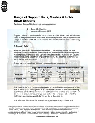
Synthesis Gas and Refinery Hydrogen Applications Support balls or more accurately, support balls and hold-down balls will at times need to be specified to our customers. Advice may also be needed opposite the usage of meshes and hold-down screens. This brief report focuses on some key aspects to consider. 1. Support Balls 2. Hold-down Balls 3. Meshes over Exit Collector & Exit Screen 4. Hold-down Screens 5. Support and Hold-down Ball Compositions and Applications 6. High Surface Area Dust Collectors

Recommended
Recommended
More Related Content
What's hot
What's hot (20)
Similar to Usage of Support Balls, Meshes & Hold Down Screens
Similar to Usage of Support Balls, Meshes & Hold Down Screens (20)
More from Gerard B. Hawkins
More from Gerard B. Hawkins (20)
Recently uploaded
Recently uploaded (20)
Usage of Support Balls, Meshes & Hold Down Screens
- 1. Refinery Process Stream Purification Refinery Process Catalysts Troubleshooting Refinery Process Catalyst Start-Up / Shutdown Activation Reduction In-situ Ex-situ Sulfiding Specializing in Refinery Process Catalyst Performance Evaluation Heat & Mass Balance Analysis Catalyst Remaining Life Determination Catalyst Deactivation Assessment Catalyst Performance Characterization Refining & Gas Processing & Petrochemical Industries Catalysts / Process Technology - Hydrogen Catalysts / Process Technology – Ammonia Catalyst Process Technology - Methanol Catalysts / process Technology – Petrochemicals Specializing in the Development & Commercialization of New Technology in the Refining & Petrochemical Industries Web Site: www.GBHEnterprises.com Usage of Support Balls, Meshes & Hold- down Screens Synthesis Gas and Refinery Hydrogen Applications By: Gerard B. Hawkins Managing Director, CEO Support balls or more accurately, support balls and hold-down balls will at times need to be specified to our customers. Advice may also be needed opposite the usage of meshes and hold-down screens. This brief report focuses on some key aspects to consider. 1. Support Balls Balls are needed to support the catalyst bed. This primarily allows the exit collector and screen to have sufficiently sized slots/holes to avoid adding to the reactor pressure drop and clog-up with catalyst dust etc. Thus balls are usually filled in graduating sizes from large at the bottom. The attached sketch shows some typical arrangements. These are only guidelines, but can be generally recommended:- Support balls on top of Support Screen Support balls filled in base of reactor Thickness Size of balls Thickness Size of balls Top Layer 100mm (4") 6mm - 13mm (1/4" -1/2") 100mm (4") 1/4" - 1/2" Bottom Layer 150mm (6") 25mm (1") As needed 25mm - 50mm (1" - 2") The sizes of the slots or mesh holes needs to be understood with relation to the size of the support ball adjacent to it. There are examples of the ball size being such that every third mesh hole would be theoretically blocked by a support ball. Under such circumstance, a larger size ball would be needed otherwise the ball/mesh combination would start to act like a filter (see 3). The minimum thickness of a support ball layer is practically 100mm (4").
- 2. Refinery Process Stream Purification Refinery Process Catalysts Troubleshooting Refinery Process Catalyst Start-Up / Shutdown Activation Reduction In-situ Ex-situ Sulfiding Specializing in Refinery Process Catalyst Performance Evaluation Heat & Mass Balance Analysis Catalyst Remaining Life Determination Catalyst Deactivation Assessment Catalyst Performance Characterization Refining & Gas Processing & Petrochemical Industries Catalysts / Process Technology - Hydrogen Catalysts / Process Technology – Ammonia Catalyst Process Technology - Methanol Catalysts / process Technology – Petrochemicals Specializing in the Development & Commercialization of New Technology in the Refining & Petrochemical Industries Web Site: www.GBHEnterprises.com 2. Hold-down Balls The application of hold-down balls is far more critical. The primary purpose is to avoid any disturbance of the catalyst bed by the velocities of the inlet process feed. If any doubt exits over the specified sizes for the hold-down balls, then a check should be carried-out by the GBHE, C2 PT Process Engineering. We have formulas which allow us to predict when a given support ball will be disturbed or not by the process gas. Although the accuracy of the methods are questionable and conservative, if they indicate problems, then they should be heeded. A 19mm (3/4") hold-down ball requires a "disturbance" velocity of at least 3 times that of 3/16” sphere. As a rough rule of thumb, the minimum ball size at the top should be no smaller than 25mm (1"), but there are many applications with smaller sizes. Certainly 6mm (1/4") is very prone to movement and although more dense than most catalysts and absorbents, it makes little sense to use as a hold-down as its size is similar to that of the catalyst! Case 1 Case 2 Thickness Size of balls Thickness Size of balls Top Layer 10cm (4") 25mm - 50mm (1" -2") 15cm (6") 25mm - 50 mm 1" - 2 " Bottom Layer 10cm (4") 6mm - 13mm (1/4" - 1/2") - - Apart from the size versus "disturbance" consideration, the minimum depth of the support balls is theoretically 3 particle diameters; e.g. 114mm (4.5") for 38 mm (1.5") balls. However, even with smaller ball sizes it is not recommended to reduce the bed depth below 100 mm (4") 3. Meshes over Exit Collector & Exit Screen Provided the correct sizes of balls are used, there is little need to install meshes in the exit system. In many cases, meshes are excellent collectors of fine dust which rapidly leads to a pressure drop build-up. This ultimately leads to poor bed distribution and poor catalsyt/absorbent performance and perhaps premature plant shut-down due to pressure drop limit. We therefore do not recommend them.
- 3. Refinery Process Stream Purification Refinery Process Catalysts Troubleshooting Refinery Process Catalyst Start-Up / Shutdown Activation Reduction In-situ Ex-situ Sulfiding Specializing in Refinery Process Catalyst Performance Evaluation Heat & Mass Balance Analysis Catalyst Remaining Life Determination Catalyst Deactivation Assessment Catalyst Performance Characterization Refining & Gas Processing & Petrochemical Industries Catalysts / Process Technology - Hydrogen Catalysts / Process Technology – Ammonia Catalyst Process Technology - Methanol Catalysts / process Technology – Petrochemicals Specializing in the Development & Commercialization of New Technology in the Refining & Petrochemical Industries Web Site: www.GBHEnterprises.com 4. Hold-down Screens Historically, these were quite popular. Here, a wire mesh screen is placed between the bed and support balls to ensure that the balls do not sink down in to the bed. Such meshes are however an additional complication in bed charging and discharging and are now generally believed unnecessary. The downside is that increased care is needed to ensure complete bed coverage to a satisfactory depth without visual aid of the mesh. 5. Support and Hold-down Ball Compositions and Applications There are a variety of compositions that can be offered, but generally, this is limited to two types:- 1.SiO2/Alumina 2.Alumina The first type of ball is the cheaper and more standard one. The key disadvantage to this is the high silica content (typically 67 wt%) which can leach- out under certain conditions. This means that in the presence of process stream containing steam, the temperature should be limited to prevent the leaching-out of SiO2. The clue to the temperature threshold is the application of HTS catalyst where problems have been experienced with silica contamination of the catalyst. This therefore indicates that in the presence of wet streams, the temperature of around 300 - 350oC (572 - 662oF) might represent a limit for silica based balls. Thus for all purification (i.e. "dry"), LTS and methanation applications, high silica based balls are acceptable. For Pre-Reforming, secondary reforming, and HTS applications, we would recommend the second more expensive type; alumina balls. We are currently using high silica based balls for an isothermal shift application because the inlet temperature is less than 300oC (572oF). This may be reviewed once we obtain catalyst samples.
- 4. Refinery Process Stream Purification Refinery Process Catalysts Troubleshooting Refinery Process Catalyst Start-Up / Shutdown Activation Reduction In-situ Ex-situ Sulfiding Specializing in Refinery Process Catalyst Performance Evaluation Heat & Mass Balance Analysis Catalyst Remaining Life Determination Catalyst Deactivation Assessment Catalyst Performance Characterization Refining & Gas Processing & Petrochemical Industries Catalysts / Process Technology - Hydrogen Catalysts / Process Technology – Ammonia Catalyst Process Technology - Methanol Catalysts / process Technology – Petrochemicals Specializing in the Development & Commercialization of New Technology in the Refining & Petrochemical Industries Web Site: www.GBHEnterprises.com It is worthwhile to note that some plants are constructed by contractors who pay little attention to the types of support and hold-down balls. Purchasing of these is usually non-technical with the price being the main incentive and in many cases without the consultation of the catalyst supplier. It is therefore common to see high silica balls used throughout the plant. In severe situations, there is example of balls actually being crushed in the applications. This may be due to SiO2 leach-out and/or poor manufacturing quality of the ball itself Historically, alumina lumps were used instead or with conjunction with balls, but more recently seemed to be mostly displaced by balls. 6. High Surface Area Dust Collectors The use of inert catalyst supports to collect solids etc. on tops of beds is sometimes applied. The most "formal" application is seen with the Japanese contractor MKK who uses these routinely on the top of HTS beds when certain naphtha steam reforming catalysts are installed upstream. The reasoning is around collection of migrated potash to avoid pressure drop increase across the HTS bed. A high surface area shape, often an inert (un-dipped) reforming rasching rings, may be recommended in these applications. These have a much higher surface area than balls and also larger voidage so a greater amount of solid material may be collected prior to an observable pressure drop increase. However, it should be noted that inert catalyst supports are much less dense than support balls and may be prone to movement if the velocities are high enough. Hold-down balls are also usually still required (under inert catalyst supports).
- 5. Refinery Process Stream Purification Refinery Process Catalysts Troubleshooting Refinery Process Catalyst Start-Up / Shutdown Activation Reduction In-situ Ex-situ Sulfiding Specializing in Refinery Process Catalyst Performance Evaluation Heat & Mass Balance Analysis Catalyst Remaining Life Determination Catalyst Deactivation Assessment Catalyst Performance Characterization Refining & Gas Processing & Petrochemical Industries Catalysts / Process Technology - Hydrogen Catalysts / Process Technology – Ammonia Catalyst Process Technology - Methanol Catalysts / process Technology – Petrochemicals Specializing in the Development & Commercialization of New Technology in the Refining & Petrochemical Industries Web Site: www.GBHEnterprises.com Downflow Reactors Inert Support Ball Applications 15cm (6") of 25mm - 50mm (1" - 2") balls (May use 15cm layer of 25mm - 50mm balls on top of 10cm layer of smaller size) 10cm (4") of 6mm - 13mm (1/4" - 1/2") balls 15cm (6") of 25mm (1") balls Notes:- 1. Typical specification:- 66wt% SiO2, 25wt% Al2O3, Balance Na2O/CaO/MgO/TiO3 2. Use +99wt% alumina balls (SiO 2 <0.2wt%) for streams containing steam at temperatures greater than 300 degC (572 degF) 3. Support grids not always recommended Can plug with catalyst dust - High pressure drop. 4. Wire mesh around outlet collector not recommended Easily plugged with catalyst dust - High pressure drop 5. Floating hold-down screens not normally recommended Support grid Catalyst/Absorbent Flat Distribution Plate 15mm (3/4") slots 25mm -50mm (1"- 2") balls { 10cm (4") of 6mm - 13mm (1/4" - 1/2") balls or 15cm (6") split layer of 6mm (1/4") balls on top of 13mm (1/2") balls
- 6. Refinery Process Stream Purification Refinery Process Catalysts Troubleshooting Refinery Process Catalyst Start-Up / Shutdown Activation Reduction In-situ Ex-situ Sulfiding Specializing in Refinery Process Catalyst Performance Evaluation Heat & Mass Balance Analysis Catalyst Remaining Life Determination Catalyst Deactivation Assessment Catalyst Performance Characterization Refining & Gas Processing & Petrochemical Industries Catalysts / Process Technology - Hydrogen Catalysts / Process Technology – Ammonia Catalyst Process Technology - Methanol Catalysts / process Technology – Petrochemicals Specializing in the Development & Commercialization of New Technology in the Refining & Petrochemical Industries Web Site: www.GBHEnterprises.com Information contained in this technical document or as otherwise supplied to Users is believed to be accurate and correct at time of going to press, and is given in good faith, but it is for the User to satisfy itself of the suitability of the Product for its own particular purpose. GBH Enterprises, C2 PT, Catalyst Process Technology gives no warranty as the fitness of the Product for any particular purpose and any implied warranty or condition (statutory or otherwise) is excluded except to the extent that exclusion is prevented by law. GBH Enterprises, C2 PT accepts no liability for loss or damaged resulting from reliance on this information. Freedom, under Patent, Copyright and Designs cannot be assumed.