1. ZJ BRAKES 5-1
BRAKES
CONTENTS
page page
ABS BRAKE DIAGNOSIS . . . . . . . . . . . . . . . . . . . 3 MASTER CYLINDER—BRAKE BOOSTER—
ABS SYSTEM OPERATION . . . . . . . . . . . . . . . . 10 COMBINATION VALVE—HCU . . . . . . . . . . . . . 18
BRAKE FLUID—BRAKE BLEEDING— PARKING BRAKES . . . . . . . . . . . . . . . . . . . . . . . 51
BRAKELINES/HOSES . . . . . . . . . . . . . . . . . . . 15 REAR DISC BRAKES . . . . . . . . . . . . . . . . . . . . . 41
BRAKE PEDAL AND BRAKELIGHT SWITCH . . . 61 SERVICE BRAKE DIAGNOSIS . . . . . . . . . . . . . . . 4
DISC BRAKE ROTOR SERVICE . . . . . . . . . . . . . 48 SPECIFICATIONS . . . . . . . . . . . . . . . . . . . . . . . . 63
FRONT DISC BRAKES . . . . . . . . . . . . . . . . . . . . 33 SPEED SENSORS—TONE WHEELS—
GENERAL INFORMATION . . . . . . . . . . . . . . . . . . 1 ACCELERATION SWITCH—ECU . . . . . . . . . . . 29
GENERAL INFORMATION
INDEX
page page
ABS Brakes . . . . . . . . . . . . . . . . . . . . . . . . . . . . . . 1 Brake Warning Lights . . . . . . . . . . . . . . . . . . . . . . . 2
Brake Changes for 1995 . . . . . . . . . . . . . . . . . . . . . 1 Brakelining Material . . . . . . . . . . . . . . . . . . . . . . . . 2
Brake Fluid/Lubricants/Cleaning Solvents . . . . . . . . . 2 Parking Brake Mechanism . . . . . . . . . . . . . . . . . . . . 1
Brake Safety Precautions . . . . . . . . . . . . . . . . . . . . 2 Wheel Brake Components . . . . . . . . . . . . . . . . . . . . 1
WHEEL BRAKE COMPONENTS BRAKE CHANGES FOR 1995
All Grand Cherokee models are equipped with A different master cylinder, power brake booster,
power assist four-wheel disc brakes. Antilock (ABS) and HCU are used in the 1995 Grand Cherokee ABS
brakes are also standard equipment on all models. system.
Single piston, disc brake calipers are used front The master cylinder reservoir has a single filler cap
and rear. Ventilated disc brake rotors are used at the and is no longer interconnected with the HCU. The
front and solid rotors are used at the rear. new HCU has built-in accumulators. The pedal travel
Power brake assist is supplied by a vacuum oper- sensor has been eliminated which means the power
ated, dual diaphragm power brake booster. brake booster is different as a result.
The master cylinder used for all applications has The rear disc brakeshoes and caliper bracket are
an aluminum body and nylon reservoir with single new for 1995. The bracket ledges are machined to ac-
filler cap. commodate the changed brakeshoes. The outboard
A combination valve is used for all applications. brakeshoes now have anti-rattle springs and the in-
The valve contains a pressure differential switch and board shoe has a wear warning strip attached.
rear brake proportioning valve. The rear disc splash shield is now secured to the
caliper bracket with two factory installed rivets. Al-
ABS BRAKES though the rivets have to be drilled out to separate
The antilock system is an electronically operated the shield from the bracket, the rivets do not have to
all wheel brake control system. The system is de- be replaced afterward. Refer to the service proce-
signed to prevent wheel lockup during periods of dures in the parking brake section.
high wheel slip when braking.
The antilock electronic control system is separate PARKING BRAKE MECHANISM
from other electrical circuits in the vehicle. A sepa- The parking brake mechanism consists of a cable
rate electronic control unit (ECU) is used for the ABS operated, dual shoe, drum brake mechanism. The
system. brake shoes operate within a drum cast into the rear
disc brake rotor. The shoes are mounted on a splash
2. 5-2 BRAKES ZJ
shield attached to the caliper bracket and rear axle CAUTION: Never use gasoline, kerosene, methyl or
tube flange. Parking brake adjustment is controlled isopropyl alcohol, paint thinner, or any fluid con-
by a cable tensioner mechanism. taining mineral oil to clean the system components.
These fluids damage rubber cups and seals. If sys-
BRAKE WARNING LIGHTS tem contamination is suspected, check the fluid for
All Grand Cherokee models have two brake warn- dirt, discoloration, or separation into distinct layers.
ing lights. A red light is used for the service and Drain and flush the system with new brake fluid if
parking brake system. An amber light is used for the contamination is suspected.
ABS system. Both lights are in the instrument clus-
ter.
The red light alerts the driver if a pressure differ- BRAKE SAFETY PRECAUTIONS
ential exists between the front and rear hydraulic
systems. The red light also alerts the driver when WARNING: ALTHOUGH FACTORY INSTALLED
the parking brakes are applied. BRAKELINING ON GRAND CHEROKEE MODELS IS
The amber antilock light only illuminates when an MADE FROM ASBESTOS FREE MATERIALS, SOME
antilock system fault occurs. AFTER MARKET BRAKELINING MAY CONTAIN AS-
Both lights illuminate for about 1-2 seconds at en- BESTOS. THIS SHOULD BE TAKEN INTO ACCOUNT
gine start; this occurs as part of a normal bulb check. WHEN SERVICING A VEHICLE WITH PRIOR BRAKE
SERVICE. WEAR A RESPIRATOR WHEN CLEANING
BRAKELINING MATERIAL BRAKE COMPONENTS AS ASBESTOS FIBERS CAN
Factory installed front and rear brakelining on BE A HEALTH HAZARD. NEVER CLEAN BRAKE
Grand Cherokee models, is made from organic mate- COMPONENTS WITH COMPRESSED AIR. USE A
rials combined with metallic particles. The brakelin-
VACUUM CLEANER SPECIFICALLY DESIGNED FOR
ing material does not contain asbestos.
REMOVING BRAKE DUST. IF A VACUUM CLEANER
BRAKE FLUID/LUBRICANTS/CLEANING SOLVENTS IS NOT AVAILABLE, CLEAN THE PARTS WITH WA-
Recommended brake fluid is Mopar brake fluid, or TER DAMPENED SHOP RAGS. DO NOT CREATE
equivalent meeting SAE J1703 and DOT 3 stan- DUST BY SANDING BRAKELINING. DISPOSE OF
dards. ALL DUST AND DIRT SUSPECTED OF CONTAINING
Use Mopar multi-mileage grease to lubricate drum ASBESTOS FIBERS IN SEALED BAGS OR CON-
brake pivot pins and rear brakeshoe contact points TAINERS. FOLLOW ALL RECOMMENDED SAFETY
on the support plates. Use GE 661 or Dow 111 sili- PRACTICES PRESCRIBED BY THE OCCUPATIONAL
cone grease, or multi-mileage grease on caliper bush- SAFETY AND HEALTH ADMINISTRATION (OSHA)
ings and slide pins. AND THE ENVIRONMENTAL PROTECTION AGENCY
Use Mopar Brake Cleaner, or fresh brake fluid to (EPA), FOR HANDLING AND DISPOSAL OF PROD-
clean or flush brake system components. These are UCTS CONTAINING ASBESTOS.
the only cleaning materials recommended.
3. ZJ ABS BRAKE DIAGNOSIS 5-3
ABS BRAKE DIAGNOSIS
INDEX
page page
ABS Diagnostic Connector . . . . . . . . . . . . . . . . . . . 3 General Information . . . . . . . . . . . . . . . . . . . . . . . . 3
ABS Warning Light Display . . . . . . . . . . . . . . . . . . . 3 Normal Operating Conditions . . . . . . . . . . . . . . . . . . 3
Antilock ECU and HCU Diagnosis . . . . . . . . . . . . . . 3 Wheel/Tire Size and Input Signals . . . . . . . . . . . . . . 3
DRB Scan Tool . . . . . . . . . . . . . . . . . . . . . . . . . . . . 3
GENERAL INFORMATION hicle wheels and tires should all be the same size
The DRB scan tool is required for all ABS diagno- and type. However, the Jeep ABS system is designed
sis. The scan tool is used to identify ABS circuit to function with a compact spare tire installed.
faults.
Once a circuit fault has been identified, refer to the NORMAL OPERATING CONDITIONS
appropriate chassis/body diagnostic manual for indi-
vidual component testing. Sound Levels
The hydraulic control unit pump and solenoid
ABS WARNING LIGHT DISPLAY valves may produce some sound as they cycle on and
The amber antilock light illuminates at startup as off. This is a normal condition and should not be mis-
part of the system self check feature. The light illu- taken for faulty operation. Under most conditions,
minates for 1-3 seconds then goes off as part of the pump and solenoid valve operating sounds will not be
normal bulb check routine. audible.
An ABS circuit fault is indicated when the amber
light remains on after startup, or illuminates at any Vehicle Response In Antilock Mode
time during vehicle operation. During antilock braking, the hydraulic control unit
Verify that a fault is actually related to the ABS solenoid valves cycle rapidly in response to antilock
system before making repairs. For example, if the electronic control unit signals.
red light illuminates but the ABS light does not, the The driver will experience a pulsing sensation
problem is related to a service brake component and
within the vehicle as the solenoids decrease, hold, or
not the ABS system. Or, if neither light illuminates
increase pressure as needed. Brake pedal pulsing will
but a brake problem is noted, again, the problem is
also be noted and is a normal condition.
with a service brake component and not with the
ABS system. Steering Response
ABS DIAGNOSTIC CONNECTOR A modest amount of steering input is required dur-
The ABS diagnostic connector is located inside the ing extremely high deceleration braking, or when
vehicle. The connecter is the access point for the braking on differing traction surfaces. An example of
DRB scan tool. differing traction surfaces would be when the left
The connector is blue or black in color and is a side wheels are on ice and the right side wheels are
6-way type. The connector is under the carpet at the on dry pavement.
forward end of the console just under the IP center.
Owner Induced Faults
DRB SCAN TOOL Driving away with the parking brakes still applied
ABS diagnosis is performed with the DRB scan will cause warning light illumination. Pumping the
tool. Refer to the DRB scan tool manual for test brake pedal will also generate a system fault and in-
hookup and procedures. Diagnosis information is pro- terfere with ABS system operation.
vided in the Chassis Diagnostic Procedures Manual
for Jeep Grand Cherokee Models. ANTILOCK ECU AND HCU DIAGNOSIS
An ECU or HCU fault can only be determined
WHEEL/TIRE SIZE AND INPUT SIGNALS through testing with the DRB scan tool. Do not re-
Antilock system operation is dependant on accurate place either component unless a fault is actually in-
signals from the wheel speed sensors. Ideally, the ve- dicated.
4. 5-4 SERVICE BRAKE DIAGNOSIS ZJ
SERVICE BRAKE DIAGNOSIS
INDEX
page page
Brake Component Inspection . . . . . . . . . . . . . . . . . . 5 Low Pedal . . . . . . . . . . . . . . . . . . . . . .... . . . . . . 5
Brake Drag . . . . . . . . . . . . . . . . . . . . . . . . . . . . . . . 5 Parking Brake Diagnosis . . . . . . . . . . . .... . . . . . . 7
Brake Fade . . . . . . . . . . . . . . . . . . . . . . . . . . . . . . 6 Pedal Falls Away . . . . . . . . . . . . . . . . .... . . . . . . 5
Brake Fluid Contamination . . . . . . . . . . . . . . . . . . . 6 Pedal Pulsation (Non-ABS Brakes Only) ... . . . . . . 6
Brake Noise . . . . . . . . . . . . . . . . . . . . . . . . . . . . . . 7 Power Brake Booster Check Valve Test .... . . . . . . 8
Brake Pull . . . . . . . . . . . . . . . . . . . . . . . . . . . . . . . 6 Power Brake Booster Vacuum Test . . . .... . . . . . . 9
Brakes Do Not Hold After Driving Through Deep Preliminary Brake Check . . . . . . . . . . . .... . . . . . . 4
Water Puddles . . . . . . . . . . . . . . . . . . . . . . . . . . . 6 Rear Brake Grab . . . . . . . . . . . . . . . . .... . . . . . . 6
Contaminated Brakelining . . . . . . . . . . . . . . . . . . . . 6 Road Test . . . . . . . . . . . . . . . . . . . . . . .... . . . . . . 5
Diagnosis Procedures . . . . . . . . . . . . . . . . . . . . . . . 4 Service Brake Warning Light Operation .... . . . . . . 5
General Information . . . . . . . . . . . . . . . . . . . . . . . . 4
Hard Pedal or High Pedal Effort . . . . . . . . . . . . . . . 5 Spongy Pedal . . . . . . . . . . . . . . . . . . . .... . . . . . . 5
GENERAL INFORMATION (2) Check condition of tires and wheels. Damaged
The diagnosis information in this section covers the wheels and worn, damaged, or underinflated tires can
vehicle service brake components which include: cause pull, shudder, tramp and a condition similar to
• disc brake calipers grab.
• disc brakeshoes (3) If complaint was based on noise when braking,
• disc brake rotors check suspension components. Jounce front and rear
• parking brake mechanism of vehicle and listen for noise that might be caused
• master cylinder by loose, worn, or damaged suspension or steering
• combination valve components.
• power brake booster (4) Inspect brake fluid level and condition. Correct
• brake pedal and brakelight switch fluid level is to FULL mark on reservoir. Remember
• red brake warning light that fluid level will decrease slightly as normal
brakelining wear occurs. If fluid level is abnormally
DIAGNOSIS PROCEDURES low, look for leaks at calipers, wheel cylinders, brake-
Service brake diagnosis involves determining if the lines and master cylinder.
problem is related to a mechanical, hydraulic or vacuum (5) Check fluid condition.
operated part. A preliminary check, road testing and (a) Fluid should be reasonably clear and free of
component inspection are needed to determine a prob- foreign material. Note that brake fluid tends to
lem cause. darken over time. This is normal and should
Road testing will either verify proper brake opera- not be mistaken for contamination. If fluid is
tion or confirm the existence of a problem. Compo- reasonably clear and free of foreign material,
nent inspection will, in most cases, identify the it is OK.
actual part causing a problem. (b) If fluid is highly discolored, or appears to con-
The first diagnosis step is the preliminary check. This tain foreign material, drain out a sample with a
involves inspecting fluid level, parking brake action, clean suction gun. Pour sample in a glass container
wheel and tire condition, checking for obvious leaks or and note condition described in step (c).
component damage and testing brake pedal response. A (c) If fluid separates into layers, or obviously con-
road test will confirm or deny the existence of a prob- tains oil or substance other than brake fluid, sys-
lem. The final diagnosis procedure involves road test tem seals and cups will have to be replaced and
analysis and a visual inspection of brake components. hydraulic system flushed.
(6) Check parking brake operation. Verify free
PRELIMINARY BRAKE CHECK movement and full release of cables and foot pedal or
(1) If amber antilock light is illuminated, refer to hand lever. Also note if vehicle was being operated
Antilock Brake System Diagnosis. However, if the with parking brake partially applied.
red warning light is illuminated, or if no warning (7) If components checked appear OK, proceed to
light is illuminated, continue with diagnosis. Road Test.
5. ZJ SERVICE BRAKE DIAGNOSIS 5-5
ROAD TEST and fluid level. If a problem is confirmed, inspect the
(1) If red light is not on, proceed to step (3). wheel brake hydraulic system.
(2) If red light is on, proceed as follows: The amber antilock warning light illuminates only
(a) See if parking brakes are applied. Release when an ABS circuit fault has occurred. Refer to the
them if necessary and proceed to step (b). Antilock Brake Diagnosis section.
(b) Note if brake pedal is abnormally low. If
pedal is definitely low and red light is on, check PEDAL FALLS AWAY
front and rear brake hydraulic circuits for leak. Do A brake pedal that falls away under steady foot
not continue with road test. Inspect and re- pressure is generally the result of a system leak. The
pair hydraulic components as needed. leak point could be at a brakeline, fitting, hose, or
(3) Check brake pedal response with transmission caliper. Internal leakage in the master cylinder
in Neutral and engine running. caused by worn or damaged piston cups, may also be
(a) If pedal remains firm under steady foot pres- the problem cause.
sure, proceed to step (4). If leakage is severe, fluid will be evident at or
(b) If pedal falls away, problem is in master cyl- around the leaking component. However internal
inder, or HCU on ABS models. Do not road test leakage in the master cylinder may not be physically
vehicle; repair as necessary instead. evident. Refer to the cylinder test procedure in this
(4) During road test, make normal and firm brake section.
stops in 25-40 mph range. Note faulty brake opera-
tion such as hard pedal, pull, grab, drag, noise, fade, LOW PEDAL
pedal pulsation, etc. If a low pedal is experienced and the red light is
(5) Inspect brake components after road test and not on, worn lining and rotors are the most likely
refer to problem diagnosis information for causes of cause.
various brake conditions. If the red warning light is on, a system leak has
occurred. A leak at a front or rear caliper, brakeline,
BRAKE COMPONENT INSPECTION or brake hose will activate the differential pressure
Fluid leak points and dragging brake units can switch in the combination valve. The switch will
usually be located without removing any components. shuttle forward or rearward depending on where the
The area around a leak point will be wet with fluid. leak is. Switch movement in either direction will
The components at a dragging brake unit (wheel, complete the electrical circuit to the red warning
tire, rotor) will be quite warm or hot to the touch. light causing the light to illuminate.
Other brake problem conditions will require compo-
nent removal for proper inspection. Raise the vehicle SPONGY PEDAL
and remove the necessary wheels for better visual ac- A spongy pedal is caused by air in the brake hy-
cess. draulic system. Brake bleeding will be necessary to
During inspection, pay particular attention to purge the air.
heavily rusted/corroded brake components (e.g. ro- Air enters the system through leak points and when
tors, caliper pistons, cables, brakelines, etc.). the master cylinder reservoir runs dry as a result of a
Heavy accumulations of rust may be an indicator of leak. Allowing the cylinder to run dry during brake
rust and corrosion damage to a brake component. It bleeding, will also allow air into the system.
is wise to remove surface rust in order to accurately
determine the depth of rust penetration and damage. HARD PEDAL OR HIGH PEDAL EFFORT
Light surface rust is normal and not a major con- A hard pedal or high pedal effort may be due to lin-
cern (as long as it is removed, or neutralized). How- ing that is water soaked, contaminated, glazed, or se-
ever, heavy rust buildup, especially on high mileage verely worn.
vehicles, may actually cover structural damage to The power brake booster, or booster check valve
such important components as: brakelines, rotors, or could also be faulty. Loss of brake boost will cause a
brake booster. hard pedal and high effort. Test the booster and
valve as described in this section.
SERVICE BRAKE WARNING LIGHT OPERATION
The red warning light illuminates when the park- BRAKE DRAG
ing brakes are applied and when there is a leak in Brake drag occurs when the lining is in constant
the front or rear wheel brake hydraulic circuit. It will contact with the rotor. Drag can occur at one wheel,
also illuminate at startup as part of a bulb check. all wheels, fronts only, or rears only. It is a product of
If the light comes on, first verify that the parking incomplete brakeshoe release. Drag can be minor or
brakes are fully released. Then check pedal action severe enough to overheat the linings and rotors.
6. 5-6 SERVICE BRAKE DIAGNOSIS ZJ
Brake drag also has a direct effect on fuel economy. If stops. If pulsation occurs during light to moderate
undetected, minor brake drag can be misdiagnosed as brake stops, a standard brake part is either loose, or
an engine or transmission/torque converter problem. worn beyond tolerance.
Minor drag will usually cause slight surface char-
ring of the lining. It can also generate hard spots in BRAKE PULL
rotors from the overheat-cool down process. In most A front pull condition that only occurs when the
cases, the rotors, wheels and tires are quite warm to brakes are applied, could result from contaminated
the touch after the vehicle is stopped. lining in one caliper, seized caliper piston, binding
Severe drag can char brakelining all the way caliper, loose caliper, loose or corroded slide pins, im-
through. It can also distort and score rotors to the proper brakeshoes, or a damaged rotor.
point of replacement. The wheels, tires and brake A worn, damaged wheel bearing or suspension com-
components will be extremely hot. In severe cases, ponent are further causes of pull. A damaged front
the lining may generate smoke as it chars from over- tire (bruised, ply separation) can also cause constant
heating. pull that is magnified when the brakes are applied.
Common causes of brake drag are: A common and confusing pull condition is where di-
• seized or sticking caliper piston rection of pull changes after a few brake stops. The
• caliper binding (on bushings, bolts, bracket) cause is a combination of brake drag followed by fade
• incorrect length caliper mounting bolts (too long) at the dragging brake unit.
• loose or damaged wheel bearing As the dragging brake overheats, efficiency is so re-
• loose caliper mounting bracket duced that fade occurs. If the opposite brake unit is
• misassembled components still functioning normally, its braking effect is magni-
• mispositioned brakelight switch fied. This causes pull to switch direction in favor of
• binding brake pedal the brake unit that is functioning normally.
• master cylinder internal fault When diagnosing a change in pull condition, re-
If brake drag occurs at all wheels, the problem may member that pull will return to the original direction
be related to a blocked master cylinder compensator if the dragging brake unit is allowed to cool down
port or faulty power booster (binds-does not release). (and is not seriously damaged).
The condition will worsen as system component tem-
REAR BRAKE GRAB
perature increases.
Rear grab is usually caused by contaminated lin-
An improperly mounted or adjusted brakelight
ing, bent or binding shoes, or improperly assembled
switch can prevent full brake pedal return. The re-
components.
sult will be the same as if the cylinder compensator
ports are blocked. In this case, the brakes would be BRAKES DO NOT HOLD AFTER DRIVING THROUGH
partially applied all the time causing drag (which
DEEP WATER PUDDLES
will become more severe as component temperature
This condition is generally caused by water soaked
increases). lining. If the lining is only wet, it can be dried by
driving with the brakes lightly applied for a mile or
BRAKE FADE two. However, if the lining is also dirty, shoe removal
Brake fade is a product of overheating caused by and cleaning with brake cleaner will be necessary.
brake drag. However, brake overheating and subse-
quent fade can also be caused by riding the brake CONTAMINATED BRAKELINING
pedal, making repeated high deceleration stops in a Brakelining contaminated by water is salvageable.
short time span, or constant braking on steep roads. The lining can either be air dried or dried using heat.
Refer to the Brake Drag information in this section In cases where brakelining is contaminated by oil,
for causes. grease, or brake fluid, the lining should be replaced.
Replacement is especially necessary when fluids/lu-
PEDAL PULSATION (NON-ABS BRAKES ONLY) bricants have actually soaked into the lining mate-
Pedal pulsation is caused by brake parts that are rial. However, grease or dirt that gets onto the lining
loose, or out of tolerance limits. This type of pulsa- surface (from handling) during brake repairs, can be
tion is experienced every time the brakes are applied. cleaned off. Simply spray the lining surface clean
Disc brake rotors with excessive lateral runout or with Mopar brake cleaner.
thickness variation, or out of round brake drums are
the primary causes of pulsation. BRAKE FLUID CONTAMINATION
On vehicles with ABS brakes, remember that pedal There are two basic causes of brake fluid contami-
pulsation is normal during antilock mode brake nation. The first involves allowing dirt, debris, or
other liquid materials to enter the cylinder reservoir
7. ZJ SERVICE BRAKE DIAGNOSIS 5-7
when the cap or cover is off. The second involves top- Loud brake squeak, squeal, scraping, or grinding
ping off, or filling the reservoir with non-recom- sounds are a sign of severely worn brake lining. If
mended fluid. the lining has worn completely through in spots, met-
Brake fluid contaminated with only dirt, or debris al-to-metal contact occurs. If the condition is allowed
usually retains a normal appearance. Generally, the to continue, rotors can become scored severely
foreign material will remain suspended in the fluid enough to require replacement.
and be visible. The fluid and foreign material can be
removed from the reservoir with a suction gun but Thump/Clunk
only if the brakes have not been applied. If the Thumping or clunk noises during braking are fre-
brakes are applied after contamination, system flush- quently not caused by brake components. In many
ing will be required. The master cylinder will also cases, such noises are caused by loose or damaged
have to be flushed or replaced if the contaminants steering, suspension, or engine components. However,
cannot be removed. Foreign material lodged in the calipers that bind on the slide surfaces can generate
reservoir compensator/return ports can cause brake a thump or clunk noise. In addition, worn out, im-
drag by restricting fluid return after brake applica- properly adjusted, or improperly assembled rear
tion. brakeshoes can also produce a thump noise.
Brake fluid contaminated by a non-recommended
fluid, may appear highly discolored, milky, oily look- Chatter/Shudder
ing, or foamy. In some cases, the fluid may even ap- Brake chatter is usually caused by loose or worn
pear to contain sludge. However, be advised that components, or glazed/burnt lining. Rotors with hard
brake fluid will darken in time and occasion- spots can also contribute to chatter. Additional causes
ally be cloudy in appearance. These are normal of chatter are out-of-tolerance rotors, brake lining not
conditions and should not be mistaken for con- securely attached to the shoes, loose wheel bearings
tamination. and contaminated brake lining.
If some type of oil has been added to the system,
the fluid will separate into distinct layers. To verify BRAKELINING CONTAMINATION
this, drain off a sample with a clean suction gun. Brakelining contamination is a product of leaking
Then pour the sample into a glass container and ob- calipers or wheel cylinders, driving through deep wa-
serve fluid action. If the fluid separates into distinct ter puddles, or lining that has become covered with
layers, it is definitely contaminated. grease and grit during repair.
The only real correction for contamination, is to
disassemble and flush the entire hydraulic system WHEEL AND TIRE PROBLEMS
and replace all seals. Some conditions attributed to brake components
may actually be caused by a wheel or tire problem.
BRAKE NOISE A damaged wheel can cause shudder, vibration and
pull. A worn or damaged tire can also cause pull.
Squeak/Squeal Severely worn tires with little or no tread left can
Factory installed brakelining is made from as- produce a grab-like condition as the tire loses and re-
bestos free materials. These materials have dif- covers traction.
ferent operating characteristics than previous Flat-spotted tires can cause vibration and wheel
brakelining material. Under certain conditions, tramp and generate shudder during brake operation.
asbestos free lining may generate some squeak, A tire with internal damage such as a severe bruise
groan or chirp noise. This noise is considered or ply separation can cause pull and vibration.
normal and does not indicate a problem. The
only time inspection is necessary, is when noise PARKING BRAKE DIAGNOSIS
becomes constant or when grinding, scraping
noises occur. Adjustment Mechanism
The rear brakeshoes are equipped with wear warn- Parking brake adjustment is controlled by a
ing tabs. The tabs contact the rotors when the lining cable tensioner. Once the tensioner is adjusted
wears to replacement thickness. A constant scraping,
at the factory, it should not require further at-
squeak type noise will occur at contact.
tention. However, there are two instances when
Constant brake squeak or squeal may be due to lin-
adjustment will be required. The first is when a
ings that are wet or contaminated with brake fluid,
new tensioner, or cables have been installed.
grease, or oil. Glazed linings and rotors with hard
spots will produce squeak. Dirt and foreign material And the second, is when the tensioner and ca-
embedded in the brake lining will also cause squeak/ bles are disconnected for access to other brake
squeal. components.
8. 5-8 SERVICE BRAKE DIAGNOSIS ZJ
Parking Brake Switch And Warning Light Illumination Parking brake adjustment and parts replacement
The parking brake switch is in circuit with the red procedures are described in the Parking Brake sec-
warning light in the dash. The switch will cause the tion.
light to illuminate only when the parking brakes are
applied. If the light remains on after parking brake POWER BRAKE BOOSTER CHECK VALVE TEST
release, the switch or wires are faulty, or cable ten- (1) Disconnect vacuum hose from check valve.
sioner adjustment is incorrect. (2) Remove check valve and valve seal from
If the red light comes on while the vehicle is in mo- booster (Fig. 1). Inspect seal for cuts, cracks, tears,
tion and brake pedal height decreases, a fault has oc- and replace if necessary.
curred in the front or rear brake hydraulic system. (3) Hand operated vacuum pump can be used for
test (Fig. 2).
Parking Brake problem Causes
(4) Apply 15-20 inches vacuum at large end of
In most cases, the actual cause of an improperly check valve (Fig. 1).
functioning parking brake (too loose/too tight/wont (5) Vacuum should hold steady. If gauge on pump
hold), can be traced to a parking brake component.
indicates any vacuum loss, valve is faulty and must
The leading cause of improper parking brake
be replaced.
operation, is excessive clearance between the
parking brakeshoes and the shoe braking sur-
face. Excessive clearance is a result of lining
and/or drum wear, drum surface machined
oversize, or inoperative adjuster components.
Excessive parking brake lever travel (sometimes
described as a loose lever or too loose condition), is
the result of worn brakeshoes, improper brakeshoe
adjustment, or improperly assembled brake parts.
A ‘‘too loose’’ condition can also be caused by inop-
erative or improperly assembled parking brakeshoe
parts.
A condition where the parking brakes do not hold,
will most probably be due to a wheel brake compo-
nent.
Items to look for when diagnosing a parking brake
problem, are:
• rear brakeshoe wear Fig. 1 Vacuum Check Valve And Seal Location
• drum surface (in rear rotor) machined oversize
• front cable not secured to lever
• rear cable not attached to lever
• rear cable seized
• parking shoes reversed
• parking brake strut not seated in shoes
• parking brake lever not seated
• parking brake lever bind
• cam and lever worn or misassembled
• adjuster screws seized
• adjuster screws reversed Fig. 2 Typical Hand Operated Vacuum Pump
9. ZJ SERVICE BRAKE DIAGNOSIS 5-9
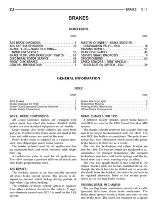
POWER BRAKE BOOSTER VACUUM TEST
(1) Connect a vacuum gauge to the booster check
valve with a short length of hose and a T-fitting (Fig.
3).
(2) Start and run engine at idle speed for one
minute.
(3) Clamp hose shut between vacuum source and
check valve (Fig. 3).
(4) Stop engine and observe vacuum gauge.
(5) If vacuum drops more than one inch HG (33
millibars) within 15 seconds, booster diaphragm or
check valve is faulty.
Fig. 3 Booster Vacuum Test Connections
10. 5 - 10 ABS SYSTEM OPERATION ZJ
ABS SYSTEM OPERATION
INDEX
page page
ABS Diagnostic Connector . . . . . . . . . . . . . . . . . . 11 Hcu Operation . . . . . . . . . . . . . . . . . . . . . . . . . . . 13
ABS Operation in Antilock Braking Mode . . . . . . . . 12 Hydraulic Control Unit (HCU) . . . . . . . . . . . . . . . . . 10
ABS Operation in Normal Braking Mode . . . . . . . . 12 Ignition Switch . . . . . . . . . . . . . . . . . . . . . . . . . . . 12
ABS System Power-Up and Initialization . . . . . . . . 12 System Description . . . . . . . . . . . . . . . . . . . . . . . . 10
Acceleration Switch . . . . . . . . . . . . . . . . . . . . . . . . 11 System Relays . . . . . . . . . . . . . . . . . . . . . . . . . . . 12
Acceleration Switch Operation . . . . . . . . . . . . . . . . 14 System Warning Light . . . . . . . . . . . . . . . . . . . . . . 12
Combination Valve . . . . . . . . . . . . . . . . . . . . . . . . 12 Wheel Speed Sensor Operation . . . . . . . . . . . . . . 13
ECU Operation . . . . . . . . . . . . . . . . . . . . . . . . . . . 14 Wheel Speed Sensors . . . . . . . . . . . . . . . . . . . . . . 11
Electronic Control Unit (ECU) . . . . . . . . . . . . . . . . 11
SYSTEM DESCRIPTION • electronic control unit (ECU)
The Jeep antilock brake system (ABS) is an elec- • wheel speed sensors and axle shaft tone rings
tronically operated, all wheel brake control system. • acceleration switch
The system is designed to prevent wheel lockup and • main relay, pump motor relay,
maintain steering control during periods of high • pump motor speed sensor
wheel slip when braking. Preventing wheel lockup • ABS warning light
and is accomplished by modulating fluid pressure to
the wheel brake units. HYDRAULIC CONTROL UNIT (HCU)
The hydraulic system is a three channel design. The hydraulic control unit (HCU) consists of a
The front wheel brakes are controlled individually valve body, pump body, accumulators, pump motor,
and the rear wheel brakes in tandem (Fig. 1). The and wire harnesses (Fig. 2).
ABS electrical system is separate from other electri- The pump body, motor, and accumulators are com-
cal circuits in the vehicle. A specially programmed bined into an assembly attached to the valve body.
electronic control unit (ECU) operates the system The accumulators store the fluid released for ABS
components. mode operation. The pump provides the fluid volume
needed for antilock braking and a DC-type motor
runs the pump. The pump/motor is controlled by the
ECU.
The valve body contains solenoid valves. The sole-
noid valves modulate brake pressure during antilock
braking. The valves are controlled by the ECU.
The HCU provides three channel pressure control
to the front and rear brakes. One channel controls
the rear wheel brakes in tandem. The two other
channels control the front wheel brakes individually.
During antilock braking, the solenoid valves are
opened and closed as needed. The valves are not
static. They are cycled rapidly and continuously to
modulate pressure and control wheel slip and decel-
eration.
At the start of antilock braking, pedal height will
decrease as the initial volume of fluid is released to
the accumulators. The accumulators then provide the
fluid needed for initial operation. The pump motor
runs continuously until the ABS mode brake stop is
completed.
The 1995 master cylinder and HCU are different
Fig. 1 Jeep AntiLock System from previous models. The new HCU has built-in ac-
cumulators that store the fluid released for antilock
ABS system components include: braking. The new master cylinder has a single filler
• hydraulic control unit (HCU) cap and the reservoir and HCU are no longer inter-
11. ZJ ABS SYSTEM OPERATION 5 - 11
connected by hoses. The 1995 ABS components are
not interchangeable with prior year ABS compo-
nents.
Fig. 2 Antilock Hydraulic Control Unit (HCU)
Fig. 3 Anti-Lock ECU
ELECTRONIC CONTROL UNIT (ECU)
An electronic control unit (ECU) operates the ABS
system (Fig. 3). The ECU is separate from other ve-
hicle electrical circuits. ECU voltage source is
through the ignition switch in the Run position.
The ECU is located in the engine compartment. It
is mounted on the driver side inner fender panel.
The ECU contains dual microprocessors. A logic
block in each microprocessor receives identical sensor
signals which are processed and compared simulta-
neously.
The ECU contains a self check program that illu-
minates the ABS warning light when a system fault
is detected. Faults are stored in a diagnostic program
memory and are accessible with the DRB scan tool.
ABS faults remain in memory until cleared, or un-
til after the vehicle is started approximately 50 Fig. 4 Wheel Speed Sensors
times. Stored faults are not erased if the battery is
ABS DIAGNOSTIC CONNECTOR
disconnected.
ABS circuit diagnosis is performed with the DRB
scan tool. The access point for the scan tool is the di-
WHEEL SPEED SENSORS
agnostic connector.
A speed sensor is used at each wheel. The sensors
The connector is under the carpet at the forward
convert wheel speed into an electrical signal. This
end of the console just under the IP center. The con-
signal is transmitted to the antilock ECU.
nector is black or blue in color and is a 6-way type.
A gear type tone ring serves as the trigger mecha-
nism for each sensor. The tone rings are mounted at
the outboard ends of the front and rear axle shafts.
ACCELERATION SWITCH
Different sensors are used at the front and rear An acceleration switch (Fig. 5), provides an addi-
wheels (Fig. 4). The front/rear sensors have the same tional vehicle deceleration reference during 4-wheel
electrical values but are not interchangeable. drive operation. The switch is monitored by the an-
12. 5 - 12 ABS SYSTEM OPERATION ZJ
tilock ECU at all times. The switch reference signal ABS SYSTEM POWER-UP AND INITIALIZATION
is utilized by the ECU when all wheels are deceler- battery voltage is supplied to the ECU ignition ter-
ating at the same rate. minal when the ignition switch is turned to Run po-
sition. The ECU performs a system initialization
procedure at this point. Initialization consists of a
static and dynamic self check of system electrical
components.
The static check occurs immediately after the igni-
tion switch is turned in Run position. The dynamic
check occurs when vehicle road speed reaches ap-
proximately 10 kph (6 mph). During the dynamic
check, the ECU briefly cycles the pump to verify op-
eration and the HCU solenoids are checked.
If an ABS component exhibits a fault during initial-
ization, the ECU illuminates the amber warning
light and registers a fault code in the microprocessor
memory.
ABS OPERATION IN NORMAL BRAKING MODE
The ECU monitors wheel speed sensor inputs con-
tinuously while the vehicle is in motion. However,
the ECU will not activate any ABS components as
Fig. 5 Acceleration Switch long as sensor inputs and the acceleration switch in-
dicate normal braking.
SYSTEM RELAYS During normal braking, the master cylinder, power
The ABS system has two relays, which are the booster and wheel brake units all function as they
main and motor pump relays. The motor pump relay would in a vehicle without ABS. The HCU pump and
is used for the motor pump only. The main relay is solenoids are not activated.
used for the solenoid valves. The main relay is con-
nected to the ECU at the power control relay termi- ABS OPERATION IN ANTILOCK BRAKING MODE
nal. The pump motor relay starts/stops the pump The purpose of the antilock system is to prevent
motor when signaled by the ECU. wheel lockup during periods of high wheel slip. Pre-
venting lockup helps maintain vehicle braking action
IGNITION SWITCH and steering control.
The antilock ECU and warning light are in standby The antilock ECU activates the system whenever
mode with the ignition switch in Off or Accessory po- sensor signals indicate periods of high wheel slip.
sition. No operating voltage is supplied to the system High wheel slip can be described as the point where
components. wheel rotation begins approaching zero (or lockup)
A 12 volt power feed is supplied to the ECU and during braking. Periods of high wheel slip may occur
warning light when the ignition switch is in the Run when brake stops involve high rates of vehicle decel-
position. eration.
The antilock system prevents lockup during high
SYSTEM WARNING LIGHT slip conditions by modulating fluid apply pressure to
The amber ABS warning light is in circuit with the the wheel brake units.
ECU and operates independently of the red brake Brake fluid apply pressure is modulated according
warning light. to wheel speed, degree of slip and rate of decelera-
The ABS light indicates antilock system condition. tion. A sensor at each wheel converts wheel speed
The light illuminates for 1-2 seconds at start-up as into electrical signals. These signals are transmitted
part of a bulb check routine. The light goes out when to the ECU for processing and determination of
the self test program determines system operation is wheel slip and deceleration rate.
normal. The ABS system has three fluid pressure control
channels. The front brakes are controlled separately
COMBINATION VALVE and the rear brakes in tandem (Fig. 1). A speed sen-
A combination valve is used with the ABS system. sor input signal indicating high slip conditions acti-
The valve contains a front/rear brake pressure differ- vates the ECU antilock program.
ential valve and switch and a rear brake proportion- Two solenoid valves are used in each antilock con-
ing valve. trol channel. The valves are all located within the
13. ZJ ABS SYSTEM OPERATION 5 - 13
HCU valve body and work in pairs to either increase, Pressure Hold
hold, or decrease apply pressure as needed in the in- Both solenoid valves are closed in the pressure hold
dividual control channels. cycle (Fig. 7). Fluid apply pressure in the control
The solenoid valves are not static during antilock channel is maintained at a constant rate. The ECU
braking. They are cycled continuously to modulate maintains the hold cycle until sensor inputs indicate
pressure. Solenoid cycle time in antilock mode can be a pressure change is necessary. The pump does not
measured in milliseconds. run during the pressure hold cycle.
HCU OPERATION
Normal Braking
During normal braking, the HCU solenoid valves,
pump, accumulators, and motor are not activated.
The master cylinder and power booster operate the
same as a vehicle without ABS brakes.
Antilock Pressure Modulation
Solenoid valve pressure modulation occurs in three
stages which are: pressure increase, pressure hold,
and pressure decrease. The valves are all contained
in the valve body portion of the HCU.
Pressure Decrease
The outlet valve is opened and the inlet valve is
closed during the pressure decrease cycle (Fig. 6).
A pressure decrease cycle is initiated when speed
sensor signals indicate high wheel slip at one or
more wheels. At this point, the ECU opens the outlet
valve, which also opens the return circuit to the ac-
cumulators. Fluid pressure is allowed to bleed off (de- Fig. 7 Pressure Hold Cycle
crease) as needed to prevent wheel lock. Pressure Increase
Once the period of high wheel slip has ended, the The inlet valve is open and the outlet valve is
ECU closes the outlet valve and begins a pressure in- closed during the pressure increase cycle (Fig. 8). The
crease or hold cycle as needed. pressure increase cycle is used to counteract unequal
wheel speeds. This cycle controls re-application of
fluid apply pressure due to changing road surfaces or
wheel speed.
WHEEL SPEED SENSOR OPERATION
Wheel speed input signals are generated by a sen-
sor and tone ring at each wheel. The sensors, which
are connected directly to the ECU, are mounted on
brackets attached to the front steering knuckles and
rear brake support plates.
The sensor triggering devices are the tone rings
which are similar in appearance to gears. The tone
rings are located on the outboard end of each front/
rear axle shaft. The speed sensors generate a signal
whenever a tone ring tooth rotates past the sensor
pickup face.
The wheel speed sensors provide the input signal
to the ECU. If input signals indicate ABS mode brak-
ing, the ECU causes the HCU solenoids to decrease,
hold, or increase fluid apply pressure as needed.
The HCU solenoid valves are activated only when
wheel speed input signals indicate that a wheel is
Fig. 6 Pressure Decrease Cycle approaching a high slip, or lockup condition. At this
14. 5 - 14 ABS SYSTEM OPERATION ZJ
these signals for degree of deceleration and wheel
slip. If signals indicate normal braking, the solenoid
valves are not activated. However, when incoming
signals indicate the approach of wheel slip, or lockup,
the ECU cycles the solenoid valves as needed.
ACCELERATION SWITCH OPERATION
The ECU monitors the acceleration switch at all
times. The switch assembly contains three mercury
switches that monitor vehicle ride height and decel-
eration rates (G-force). Sudden, rapid changes in ve-
hicle and wheel deceleration rate, triggers the switch
sending a signal to the ECU. The switch assembly
provides three deceleration rates; two for forward
braking and one for rearward braking.
ECU OPERATION
The antilock ECU controls all phases of antilock
operation. It monitors and processes input signals
from the system sensors.
It is the ECU that activates the solenoid valves to
modulate apply pressure during antilock braking.
Fig. 8 Pressure Increase Cycle The ECU program is able to determine which wheel
point, the ECU will cycle the appropriate wheel con- control channel requires modulation and which fluid
trol channel solenoid valves to prevent slip or lockup. pressure modulation cycle to use. The ECU cycles the
The wheel sensors provide speed signals whenever solenoid valves through the pressure decrease, hold
the vehicle wheels are rotating. The ECU examines and increase phases.
15. ZJ BRAKE FLUID—BRAKE BLEEDING—BRAKELINES/HOSES 5 - 15
BRAKE FLUID—BRAKE BLEEDING—BRAKELINES/HOSES
INDEX
page page
ABS Brake Bleeding . . . . . . . . . . . . . . . . . . . . . . . 15 Correct Brake Fluid Level . . . . . . . . . . . . . . . . . . . 15
Brakelines and Hoses . . . . . . . . . . . . . . . . . . . . . . 16 Importance of Clean Brake Fluid . . . . . . . . . . . . . . 15
Checking Brake Fluid for Contamination . . . . . . . . 15 Recommended Brake Fluid . . . . . . . . . . . . . . . . . . 15
RECOMMENDED BRAKE FLUID rial in the fluid, or non-recommended fluids will
Recommended brake fluid is Mopar brake fluid, or cause system malfunctions.
an equivalent quality fluid meeting SAE J1703 and Clean the reservoir and cap thoroughly before
DOT 3 standards. checking level or adding fluid. Cap open lines and
Brake fluid used in the ABS system must not only hoses during service to prevent dirt entry.
meet SAE/DOT standards, it must be exceptionally Dirt or foreign material entering the ABS hydraulic
clean as well. Never use substandard fluid, fluid system through the reservoir opening will circulate
not meeting SAE/DOT standards, reclaimed within the system. Dirt or foreign material in the
fluid, or fluid from containers that have been system can lead to component malfunction. Always
left open for lengthy periods. clean the reservoir exterior before checking fluid
level or adding fluid. Use clean, fresh fluid only to
CORRECT BRAKE FLUID LEVEL top off, or refill the system.
Correct fluid level is marked on each the side of
the master cylinder reservoir (Fig. 1). CHECKING BRAKE FLUID FOR CONTAMINATION
Preferred fluid level is to the FULL mark. Accept- Oil in the fluid will cause brake system rubber
able fluid level is between the ADD and FULL seals to soften and swell. The seals may also become
marks.
porous and begin to deteriorate.
If fluid level is below the ADD mark, the brake hy-
If fluid contamination is suspected, drain off a sam-
draulic system should be checked for leaks.
ple from the master cylinder. A suction gun or similar
CAUTION: Clean the reservoir cap and exterior thor- device can be used for this purpose.
oughly before checking fluid level. Do not allow any Empty the drained fluid into a glass container.
dirt or foreign material to enter the reservoir while Contaminants in the fluid will cause the fluid to sep-
checking fluid level. Such materials can interfere arate into distinct layers. If contamination has oc-
with solenoid valve operation causing an ABS mal- curred, the system rubber seals, hoses and cups must
function. be replaced and the system thoroughly flushed with
clean brake fluid.
ABS BRAKE BLEEDING
ABS brake bleeding requires use of the DRB scan
tool. The procedure involves performing a conven-
tional bleed, followed by use of the scan tool to cycle
and bleed the HCU pump and solenoids. A second
conventional bleed procedure is then required to en-
sure that all air is purged from the system.
BRAKE BLEED PROCEDURE
(1) If new master cylinder is to be installed, bleed
cylinder on bench before installation in vehicle. Refer
to procedure in section covering master cylinder ser-
vice.
(2) Wipe master cylinder reservoir and cap clean.
This avoids having dirt or foreign material fall into
Fig. 1 Reservoir Fluid Level Indicator Marks
reservoir.
IMPORTANCE OF CLEAN BRAKE FLUID (3) Fill reservoir with Mopar, or equivalent quality
The ABS system brake fluid must be kept clean brake fluid meeting SAE J1703 and DOT 3 stan-
and free of any type of contamination. Foreign mate- dards.
16. 5 - 16 BRAKE FLUID—BRAKE BLEEDING—BRAKELINES/HOSES ZJ
(4) Perform conventional brake bleed as described (a) Connect scan tool to ABS diagnostic connec-
in steps (5) and (6). tor. Connector is under carpet at front of console,
(5) Bleed master cylinder and combination valve at just under instrument panel center bezel.
brakeline fittings. Have helper operate brake pedal (b) Select CHASSIS SYSTEM, followed by
while bleeding cylinder and valve. TEVES ABS BRAKES, then BLEED BRAKES.
When scan tool displays TEST COMPLETE, dis-
connect scan tool and proceed to next step.
(8) Repeat conventional bleed procedure described
in steps (5) and (6).
(9) Top off master cylinder fluid level and verify
proper brake operation before moving vehicle.
BRAKELINES AND HOSES
Metal brakelines and rubber front brake hoses
(Figs. 3 and 4), should be inspected periodically and
replaced if damaged.
The HCU lines with the braided, flexible sections
should be replaced if damaged. Do not use substitute
brakelines here. Use the flexible braided lines only.
Rubber brake hoses should be replaced if cut,
cracked, swollen, or leaking. Rubber hoses must only
be replaced. They are not repairable parts.
The steel brakelines should be checked every time
the vehicle is in for normal maintenance. This is im-
portant on high mileage vehicles. It is especially im-
portant when the vehicle is operated in areas where
Fig. 2 Bleed Hose Immersed In Fluid salt is used on road surfaces during winter.
(6) Bleed wheel brakes in recommended sequence
which is: right rear wheel; left rear wheel; right front
wheel; left front wheel. Procedure is as follows:
(a) Attach bleed hose to caliper bleed screw. Im-
merse end of hose in glass container partially filled
with brake fluid. Be sure hose end is submerged in
fluid (Fig. 2).
(b) Open bleed screw 1/2 turn. Then have helper
depress and hold brake pedal.
(c) Close bleed screw when brake pedal contacts
floorpan. Do not pump brake pedal at any time
while bleeding. This compresses air into small
bubbles which are distributed throughout
system. Additional bleeding will be necessary
to remove trapped air.
(d) Repeat bleeding operation at each wheel
brake unit until fluid entering glass container is
free of air bubbles. Check reservoir fluid level fre-
quently and add fluid if necessary.
(7) Perform HCU bleed procedure with DRB scan
tool as follows:
Fig. 3 Master Cylinder/Combination Valve/HCU
Brakeline Connections
17. ZJ BRAKE FLUID—BRAKE BLEEDING—BRAKELINES/HOSES 5 - 17
Fig. 4 Front Brakeline Routing And Connections
Heavily rusted/corroded brakelines should be care- component damage. Severely rusted parts should be
fully inspected. Heavy rust buildup can hide severe replaced if doubt exists about their condition.
18. 5 - 18 MASTER CYLINDER—BRAKE BOOSTER—COMBINATION VALVE—HCU ZJ
MASTER CYLINDER—BRAKE BOOSTER—COMBINATION VALVE—HCU
INDEX
page page
Combination Valve Installation . . . . . . . . . . . . . . . . 20 Master Cylinder Installation . . . . . . . . . ... . . . . . . 23
Combination Valve Removal . . . . . . . . . . . . . . . . . 20 Master Cylinder Removal . . . . . . . . . . ... . . . . . . 21
General Service Information . . . . . . . . . . . . . . . . . 18 Master Cylinder Reservoir Replacement .. . . . . . . 21
HCU Installation . . . . . . . . . . . . . . . . . . . . . . . . . . 25 Power Brake Booster Installation . . . . . ... . . . . . . 27
HCU Removal . . . . . . . . . . . . . . . . . . . . . . . . . . . . 23 Power Brake Booster Operation . . . . . ... . . . . . . 19
Master Cylinder Bench Bleeding . . . . . . . . . . . . . . 23 Power Brake Booster Removal . . . . . . ... . . . . . . 27
GENERAL SERVICE INFORMATION booster is different as well. The new parts on 1995
A two-piece master cylinder with a 25.4 mm bore models are not interchangeable with prior models.
and a 205 mm (8.07 in.) dual diaphragm power brake
booster are used for all applications. Component Service
A combination valve is used on all models. The The power brake booster, HCU, and combination
valve consists of a pressure differential switch and valve are not repairable. These components must be
valve, and a rear proportioning valve. replaced as an assembly whenever diagnosis indi-
cates this is necessary.
Changes For 1995 The nylon reservoir and grommets are the only ser-
A different master cylinder, brake booster, and viceable parts on the master cylinder (Fig. 1). The
HCU are used in 1995 Grand Cherokee models. combination valve bracket is an integral part of the
The master cylinder reservoir has a single filler cap valve; it is not removable.
and is no longer interconnected with the HCU. The The only serviceable parts on the power brake
new HCU has built-in accumulators to store fluid re- booster (Fig. 1) are the check valve, and vacuum
leased for antilock braking. The pedal travel sensor hose. The booster itself is not serviceable. Replace
has been eliminated which means the power brake the booster as an assembly whenever diagnosis indi-
cates a malfunction has occurred.
Fig. 1 Master Cylinder/Brake Booster Assembly
19. ZJ MASTER CYLINDER—BRAKE BOOSTER—COMBINATION VALVE—HCU 5 - 19
POWER BRAKE BOOSTER OPERATION How Brake Boost Is Generated
Power assist is generated by utilizing the pressure
Booster Components differential between normal atmospheric pressure
The booster assembly consists of a housing divided and a vacuum. The vacuum needed for booster oper-
into separate chambers by two internal diaphragms ation is taken directly from the engine intake mani-
(Fig. 2). The outer edge of each diaphragm is at- fold. The entry point for atmospheric pressure is
tached to the booster housing. The diaphragms are through a filter and inlet valve at the rear of the
connected to the booster primary push rod. housing (Fig. 2).
Two push rods are used to operate the booster. The The chamber areas forward of the booster dia-
primary push rod connects the booster to the brake phragms are exposed to manifold vacuum. The cham-
pedal. The secondary push rod, which connects the ber areas to the rear of the diaphragms, are exposed
booster to the master cylinder, strokes the master to normal atmospheric pressure of 101.3 kilopascals
cylinder pistons. (14.7 pounds/square in.).
The atmospheric inlet valve is opened and closed Depressing the brake pedal causes the primary
by the primary push rod. The booster vacuum supply push rod to open the atmospheric inlet valve. This
is through a hose attached to a fitting on the intake action exposes the area behind the diaphragms to at-
manifold. The hose is connected to a vacuum check mospheric pressure. The resulting pressure differen-
valve in the booster housing. The check valve is a tial is what provides the extra apply pressure for
one-way device that prevents vacuum leak back. power assist.
Fig. 2 Power Brake Booster Internal Components
20. 5 - 20 MASTER CYLINDER—BRAKE BOOSTER—COMBINATION VALVE—HCU ZJ
COMBINATION VALVE REMOVAL
(1) Disconnect clean air and PCV hoses. Then un-
snap and remove engine air cleaner top cover (Fig.
3). Cover intake manifold inlet with shop towel.
Fig. 5 Combination Valve Bracket Attachment
(8) Remove combination valve and bracket assem-
bly (Fig. 6).
Fig. 3 Air Cleaner Top Cover And Hoses
(2) Remove brakelines that connect master cylin-
der to combination valve (Fig. 4).
(3) Disconnect wire from combination valve switch
terminal (Fig. 4). Be careful when separating wire
connector as lock tabs are easily damaged if not fully
disengaged.
(4) Disconnect brakelines that connect combination
valve to HCU (Fig. 4).
Fig. 6 Combination Valve And Bracket Assembly
COMBINATION VALVE INSTALLATION
(1) Position valve bracket on booster studs (Fig. 7).
(2) Install but do not tighten nuts that secure
valve bracket to booster studs.
(3) Align and start all four brakeline fittings in
combination valve by hand to avoid cross threading.
Then tighten fittings just enough to prevent leakage.
(4) Tighten combination valve bracket attaching
nuts to 25 N⅐m (220 in. lbs.) torque.
(5) Connect wire to differential pressure switch in
combination valve (Fig. 4).
Fig. 4 Combination Valve Connections
(6) Tighten brakeline fittings at master cylinder
(5) Slide HCU solenoid harness connectors off com- just enough to prevent leakage.
bination valve bracket. Then move harness aside for (7) Bleed brakes. Refer to procedure in Brake
working clearance. Bleeding-Fluid Level-Brakelines section.
(6) Remove nuts attaching combination valve (8) Attach HCU solenoid harness connectors to
bracket to booster studs (Fig. 5). combination valve bracket.
(7) Slide combination valve bracket off booster (9) Install air cleaner top cover and hoses.
studs (Fig. 5).
21. ZJ MASTER CYLINDER—BRAKE BOOSTER—COMBINATION VALVE—HCU 5 - 21
(8) Remove nuts that attach master cylinder to
booster studs. a 6-point deep socket is needed to
reach nuts (Fig. 9). Retain nuts as they are spe-
cial locking types.
Fig. 7 Positioning Valve Bracket On Booster Studs Fig. 9 Master Cylinder Attaching Nut Location
MASTER CYLINDER REMOVAL (9) Remove master cylinder from booster (Fig. 10).
(1) Disconnect Loosen clamp that secures clean air
hose to intake manifold. Then disconnect PCV hose
at valve.
(2) Unsnap air cleaner top cover and remove cover
and hoses (Fig. 3). Air filter can either be removed or
covered with shop towel at this time.
(3) Cover intake manifold air inlet with shop
towel.
(4) Remove windshield washer reservoir attaching
screws. Then lift reservoir upward and position it on
top of fender (Fig. 8). It is not necessary to dis-
connect reservoir hoses or wires to position
reservoir on fender.
Fig. 10 Master Cylinder Removal
MASTER CYLINDER RESERVOIR REPLACEMENT
The only serviceable master cylinder parts are the
reservoir, grommets, and seal (Fig. 11). The cylinder
body is not a repairable item. The body and pistons
are only serviced as an assembly.
RESERVOIR AND GROMMET REPLACEMENT
(1) Remove reservoir cap and empty fluid into
drain container.
(2) Remove pins that retain reservoir to master
cylinder. Use hammer and pin punch to remove pins
(Fig. 12).
Fig. 8 Windshield Washer Reservoir Positioned On (3) Clamp cylinder body in vise with brass protec-
Fender tive jaws.
(5) Remove brakelines that connect master cylin- (4) Loosen reservoir from grommets with pry tool
der to combination valve (Fig. 4). (Fig. 13).
(6) Remove nuts that secure combination valve
bracket to booster mounting studs.
(7) Slide combination valve bracket off booster
studs (Fig. 5).
22. 5 - 22 MASTER CYLINDER—BRAKE BOOSTER—COMBINATION VALVE—HCU ZJ
Fig. 14 Reservoir Removal
Fig. 11 Master Cylinder And Reservoir Assembly
Fig. 15 Grommet Removal
(7) Lubricate new grommets with clean brake
fluid.
(8) Install new grommets in cylinder body (Fig.
16). Use finger pressure only to install and seat
grommets.
CAUTION: Do not use any type of tool to install the
grommets. Tools will cut, or tear the grommets cre-
Fig. 12 Removing/Installing Reservoir Retaining
Pins ating a leak problem after installation. Install the
grommets using finger pressure only.
Fig. 13 Loosening Reservoir From Grommets
Fig. 16 Grommet Installation
(5) Remove reservoir by rocking it to one side and
pulling free of grommets (Fig. 14). (9) Start reservoir in grommets. Then rock reser-
(6) Remove old grommets from cylinder body (Fig. voir back and forth while pressing downward to seat
15). it in grommets.
23. ZJ MASTER CYLINDER—BRAKE BOOSTER—COMBINATION VALVE—HCU 5 - 23
(10) Install pins that retain reservoir to cylinder MASTER CYLINDER INSTALLATION
body (Fig. 12). (1) If new master cylinder is being installed, re-
(11) Fill and bleed master cylinder on bench before move protective cover from end of primary piston.
installation in vehicle. Then bleed cylinder on bench as described in this
section.
MASTER CYLINDER BENCH BLEEDING (2) Slide master cylinder onto booster studs. Align
A new master cylinder should always be bled be- booster push rod in cylinder primary piston and seat
fore installation in the vehicle. This practice saves cylinder against booster.
time during brake bleeding because air in the cylin- (3) Install master cylinder attaching nuts (Fig. 18).
der will not be pumped into the lines. Tighten nuts to 25 N⅐m (220 in. lbs.) torque. Cylin-
The only tools needed for bench bleeding are a vise, der attaching nuts are special locking type. Do
a pair of bleed tubes and a wood dowel the same di- not use substitute fasteners.
ameter as the cylinder push rod. Bleed tubes can ei-
ther be purchased, or fabricated from spare
brakelines and fittings.
The bench bleeding procedure is as follows:
(1) Mount master cylinder in vise. Clamp vise jaws
on one of the cylinder mounting ears.
(2) Install bleed tubes in cylinder outlet ports and
direct tube ends into appropriate reservoir chambers
(Fig. 17).
Fig. 18 Master Cylinder Attaching Nut Removal/
Installation
(4) Mount combination valve bracket on booster
mounting studs.
(5) Install brakelines that connect master cylinder
to combination valve. Start brakeline fittings by
hand to avoid cross threading.
(6) Install nuts that attach combination valve
bracket to booster mounting studs. Tighten nuts to
Fig. 17 Typical Method Of Bench Bleeding Master 25 N⅐m (220 in. lbs.) torque.
Cylinder (7) Fill and bleed brake system.
(8) Install windshield washer reservoir.
(3) Fill reservoir chambers about 3/4 full with (9) Install engine air cleaner top cover and hoses.
fresh, clean brake fluid.
(4) Bleed cylinder by stroking cylinder pistons in- HCU REMOVAL
ward then allowing them to return under spring (1) Loosen clamp that secures clean air hose to in-
pressure. Use a wood dowel, or similar tool to stroke take manifold. Then disconnect PCV hose at valve.
pistons (Fig. 17). (2) Unsnap engine air cleaner top cover and re-
(5) Continue stroking pistons until bubbles no move cover and hoses (Fig. 19).
longer appear in fluid entering reservoir. (3) Remove filter from air cleaner housing (Fig.
(6) Remove bleed tubes and install plastic plugs in 19).
cylinder outlet ports. Plugs will prevent fluid loss (4) Remove bolts/nuts attaching air cleaner hous-
and keep dirt out until cylinder assembly is ready for ing to body panel. Then work housing off ambient air
installation. duct and remove housing from engine compartment.
(7) Top off reservoir fluid level and install cap. (5) Remove windshield washer reservoir attaching
screws. Then position on top of fender (Fig. 8). It is
not necessary to disconnect reservoir hoses or wires.
(6) Slide HCU solenoid harness connector off re-
taining tab on combination valve. Then unplug con-
24. 5 - 24 MASTER CYLINDER—BRAKE BOOSTER—COMBINATION VALVE—HCU ZJ
Fig. 21 Combination Valve Assembly Removal
(14) Remove three nuts that attach HCU bracket to
suspension support panel (Fig. 22). Retain bracket nuts.
Fig. 19 Air Cleaner Components
nector from engine compartment harness and move it
aside (Fig. 20).
Fig. 20 HCU Solenoid Harness Connector Fig. 22 Removing HCU Bracket Attaching Nuts
(7) Disconnect wire from combination valve switch (15) Disconnect HCU pump motor harness (Fig. 23).
(Fig. 4). Be careful when separating wire connector
as lock tabs are easily damaged if not fully disen-
gaged.
(8) Remove brakelines that connect master cylin-
der to combination valve (Fig. 4).
(9) Disconnect remaining two brakelines (from
HCU) at combination valve.
(10) Remove nuts attaching combination valve
bracket to booster mounting studs.
(11) Slide combination valve bracket off booster
mounting studs and remove valve (Fig. 21). If
bracket is tight fit, use pry tool to work bracket off
studs.
(12) Remove nuts attaching master cylinder to
booster mounting studs (Fig. 22). Retain cylinder
attaching nuts as they have a special interfer-
ence fit thread. Fig. 23 HCU Pump Motor Harness Connector
(13) Remove master cylinder (Fig. 10).
25. ZJ MASTER CYLINDER—BRAKE BOOSTER—COMBINATION VALVE—HCU 5 - 25
(16) Disconnect three brakelines at rear of HCU (21) Inspect rubber isolators and sleeves in HCU
(Fig. 24). These are lines that connect HCU to front/ bracket (Figs. 26 and 27). Replace any washers or
rear brakes. isolators if missing, or damaged with factory replace-
ment parts only. Do not use substitute fasteners.
Fig. 26 HCU Bracket Bolt Location
Fig. 24 Brakeline Connections
(17) If HCU is to be replaced, remove flex lines
from HCU. These are lines that connect HCU to com-
bination valve.
(18) Lift HCU and bracket off mounting studs and
remove assembly from engine compartment (Fig. 25).
(19) If HCU is to be replaced, remove three bolts
Fig. 27 HCU Bracket Isolators and Sleeves
HCU INSTALLATION
(1) If new HCU is being installed, transfer mount-
ing bracket to new HCU. Be sure to use original
shoulder style bolts to attach bracket to HCU; do not
use substitute fasteners.
(2) If stud plate that attaches HCU bracket to sus-
pension support panel, was removed, position stud
plate on underside of panel and secure it with new
retaining nuts (Fig. 29).
(3) Position HCU bracket on mounting studs (Fig.
30). Then install and tighten bracket attaching nuts
to 10-13 N⅐m (92-112 in. lbs.) torque.
(4) Align and start brakeline fittings into ports at
rear of HCU (Fig. 31). Start fittings by hand to
Fig. 25 HCU And Bracket Removal avoid cross threading. Then tighten fittings to
14-16 N⅐m (125-140 in. lbs.) torque.
attaching mounting bracket to HCU (Fig. 26). (5) Slide master cylinder onto booster studs (Fig.
(20) Separate bracket from HCU (Fig. 27). Note 32). Align booster push rod in cylinder primary pis-
that special shoulder bolts are used to attach ton and seat cylinder against booster.
bracket to HCU. If bolts are damaged, do not (6) Install and tighten master cylinder attaching
use substitute bolts. Use factory replacement nuts to 25 N⅐m (220 in. lbs.) torque. Cylinder at-
bolts only.