Micro Irrigation Design Steps
•
0 likes•220 views

This document discusses the design steps for micro irrigation systems in canal command areas. It begins by introducing micro irrigation and its advantages over traditional surface irrigation systems. It then outlines the key design considerations and steps for laying out a micro irrigation system, including dividing the study area into sections connected by pipes to a storage well. The design steps include selecting emitters based on crop type and spacing, calculating irrigation rates and durations, and designing the laterals, submains, and main pipes while accounting for head losses. The goal is to design an efficient system that supplies adequate water and pressure throughout the field to optimize irrigation.

Recommended
More Related Content
What's hot
What's hot (20)
Viewers also liked
Viewers also liked (10)
Similar to Micro Irrigation Design Steps
Similar to Micro Irrigation Design Steps (20)
Recently uploaded
Recently uploaded (20)
Micro Irrigation Design Steps
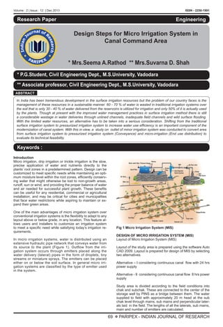
- 1. Volume : 2 | Issue : 12 | Dec 2013 ISSN - 2250-1991 69 X PARIPEX - INDIAN JOURNAL OF RESEARCH Research Paper Design Steps for Micro Irrigation System in Canal Command Area * Mrs.Seema A.Rathod ** Mrs.Suvarna D. Shah Engineering * P.G.Student, Civil Engineering Dept., M.S.University, Vadodara ** Associate professor, Civil Engineering Dept., M.S.University, Vadodara ABSTRACT In India has been tremendous development in the surface irrigation resources but the problem of our country faces is the management of these resources in a sustainable manner. 60 - 70 % of water is wasted in traditional irrigation systems over the soil that is only 30 - 40 % of water delivered from the reservoirs is utilized for irrigation and only 50% of it is actually used by the plants. Though at present with the improved water management practices in surface irrigation method there is still a considerable wastage in water deliveries through unlined channels, inadequate field channels and wild surface flooding. With the limited water resources, an alternative has to be taken into a serious consideration. Shifting from the traditional surface irrigation system to pressurized irrigation system to increase water use efficiency is an important component of the modernization of canal system. With this in view, a study on outlet of minor irrigation system was conducted to convert area from surface irrigation system to pressurized irrigation system (Conveyance) and micro-irrigation (End use distribution) to evaluate its technical feasibility. Keywords : Introduction Micro irrigation, drip irrigation or trickle irrigation is the slow, precise application of water and nutrients directly to the plants’ root zones in a predetermined pattern. Design can be customized to meet specific needs while maintaining an opti- mum moisture level within the root zones, efficiently conserv- ing water that might otherwise be lost to non-growth areas, runoff, sun or wind, and providing the proper balance of water and air needed for successful plant growth. These benefits can be useful for any residential, commercial or agricultural installation, and may be critical for cities and municipalities that face water restrictions while aspiring to maintain or ex- pand their green areas. One of the main advantages of micro irrigation system over conventional irrigation systems is the flexibility to adapt to any layout above or below grade, in any location. This feature al- lows users and installers to customize an irrigation system to meet a specific need while satisfying today’s irrigation re- quirements. In micro irrigation systems, water is distributed using an extensive hydraulic pipe network that conveys water from its source to the plant (Figure 1). Outflow from the irri- gation system occurs through emitters placed along the water delivery (lateral) pipes in the form of droplets, tiny streams or miniature sprays. The emitters can be placed either on or below the soil surface. In general micro irri- gation systems are classified by the type of emitter used in the system. Fig 1 Micro Irrigation System (MIS) DESIGN OF MICRO IRRIGATION SYSTEM (MIS) Layout of Micro Irrigation System (MIS) Layout of the study area is prepared using the software Auto CAD 2009. Layout is prepared for design of MIS by selecting two alternatives Alternative – I considering continuous canal flow with 24 hrs power supply Alternative - II considering continuous canal flow 8 hrs power supply Study area is divided according to the field conditions into chak and subchak. These are connected to the center of the storage well by PINS as a bridge between them. The water supplied to field with approximately 20 m head at the sub chak level through mains, sub mains and perpendicular later- als laid in the field. The lengths of all the laterals, sub mains, main and number of emitters are calculated.
- 2. Volume : 2 | Issue : 12 | Dec 2013 ISSN - 2250-1991 70 X PARIPEX - INDIAN JOURNAL OF RESEARCH Irrigation data required for design of MIS related to Alternative I & Alternative II are as follows: Total area of each sub chak in hectare. Types of crop considered a major crop grown in this area. Details of water source type i.e. Well, Bore well, River or Ca- nal. Details of micro irrigation system -for closely planted crops like cotton, banana, sugarcane, vegetables used in-line or online emitter or dripper system. As per selection of crop the spacing between row to row de- cided. Also considered plant to plant spacing or emitter spacing has per closely or far planted crop. The emitter is the most important part of a micro irrigation system because it delivers water at the desired rate to the plant and maintains water application uniformity over the entire irrigated area. An emitter should match particular field conditions including type of crop, spacing of the plant, water requirement, water quality, operating time, pressure head etc. Irrigation rate also called application rate is the rate of appli- cation of water per unit time expressed in depth. Unit of this is mm/hr. It is the ratio of dripper discharge (lph) with spacing of dripper (m) and lateral (m). Crop water requirement or water application per irrigation also called peak water requirement. It is the maximum wa- ter requirement of matured crop throughout day expressed in mm/day. From State Water Data Centre (SWDC) meteor- ological data are collected and using software CROPWAT 8.0, value of water requirement is determined considering a major crop as cotton in the study area. Time of irrigation per operation is the ratio of water application per irrigation to the irrigation rate. Electricity depends on policy of state. Maximum shifts as per time limitation find out by total elec- tricity available divide by time of irrigation per operation cycle. Design Steps for Components of MIS To design MIS with proper head loss calculation by Darcy – Weisbach formula. Water flows upto the crop of field without clogging problem and operation and maintenance cost min- imized. (i) Irrigation Data Q=Select emitters with discharge = 2,4,6,8 lph (As per type of crop) Sr =Lateral Spacing = spacing between row of crops Se = Emitter Spacing = Spacing between crop/ No. of emitters /plant Application Rate = Emitter Discharge / (Lateral Spacing x Emitter Spacing) Duration of irrigation =Peak water requirement (mm)/Applica- tion Rate (mm/h) (ii) Design of Laterals Select diameter ( D) of pipe in mm Find length of laterals from figure in meter. Compute thickness of lateral (t) = ( D / 15) + 0.55 mm Compute inner diameter (d) = D – ( 2 x t ) No. of emitters per laterals = Length / spacing between emit- ters Discharge (Q) at entry of laterals = Length / spacing between emitters Velocity in laterals = Q/A in m/s Reynolds No. Re = vD / µ D-W friction factor f = 0.316 / Re 0.25 Head –loss hf lat . = 6.377 fLQ2 / D5 (Q in lph,D in mm) Add 15% loss due to online laterals. Total head loss with full discharge = 1.15 x hf lat . Actual head loss = Christiansen correction factor x head loss with full dis- charge = F0.5 x hf lat . Where F= 1 / (m+1) + 1 / 2N + (m-1)1/2 / 6N2 , N= No. of outlet Fo.5 = (2NF-1) / (2N-1), m=2 for D-W EQn The operating pressure at the mid-point of middle lateral Pa = 10 m The pressure at entry point of middle lateral Pd = Pa + 0.75 Actual head loss (iii) Design of Submain Select diameter (D) of submain pipe in mm. Find length submain from figure in meter. Compute thickness of lateral (t) = ( D /15) + 0.55 mm Compute inner diameter (d) = D – ( 2 x t ) No. of laterals per submain on each side = Length / spacing bet. laterals Total no. of laterals = 2 x no. of laterals in one side Discharge at entry of submain = Total no. of laterals x lateral discharge Velocity in laterals = Q/A in m/s Reynolds No. Re = vD / µ D-W friction factor f =0.316 / Re 0.25 Head –loss hf sub. = 6.377 fLQ2 / D5 (Q in lph , D in mm) Add 20% loss due to lateral connections. Total head loss with full discharge = 1.2 x hf sub. Actual head loss = Christiansen correction factor x head loss with full discharge = F0.5 x hf sub. Where F= 1/ (m+1) + 1/ 2N + (m-1)1/2 /6N2 , N= No. of outlet Fo.5 = (2NF-1) / (2N-1), m=2 for D-W EQn The operating pressure at the mid-point of midpoint of sub- main Pa = 10 m The pressure at entry point of middle lateral Pd = Pd + 0.75 Actual head loss
- 3. Volume : 2 | Issue : 12 | Dec 2013 ISSN - 2250-1991 71 X PARIPEX - INDIAN JOURNAL OF RESEARCH REFERENCES Administrative & Technical Guideline for preparation of PINS System “by PINS Cell,SSNNL pp 1-25. | Arora, K.R. (2004). “Irrigation, Water Power and Water Resource Engineering.” Standard Published Distribution. | Bhavanishanker,B.S.,(2010.) “ Irrigation and Water Management-Operation and Maintenance of Irrigation Systems,” Water and Energy International, Water Sources Section | Chawla et. Al (2009), “ Efficient use of Canal water through Drip Irrigation in Cotton”, Indian Journal of Agri- cultural Science, Punjab Agricultural University,Ludiana. | Bramanand et. al(2001) “Drip Irrigation In India- current status and needs” | Chow .V.T, Maidment .D.K, and Mays .L.W (2002), “Applied Hydrology”, McGraw-Hill Book Company, New York, USA. | Cornish G.A.(2000) “Pressurized Irrigation Technologies for small holders”, International Conference on Micro and Sprinkler Irrigation Systems” pp 102-115 | Dalwadi H.J, Khadeja P.(2011) “Water Use And Productivity: A River basin Analysis National Conference on Recent Trends in Engineering & Technology,B.V.M. Engineering College,V.V.Nagar pp.1-4 | Jain,R.B.(2001) “Development of Micro-Irrigation in India, “Emerging Trends of Micro- Irrigation:pp.116- 124. | Kanan n.,Jeong J.(2011)Journal of Hydrologic Modeling Canal-Irrigated Agricultural Watershed with Irrigation Best Management Practices,.ASCEpp,746-757 | Minhas P.S.(2000) ‘Pressurized Irrigation Systems for Enhancing Water and Crop Productivity under Saline Irrigation ‘International Conference on Micro and Sprinkler Irrigation Systems Published by Central Board Of Irrigation.pp 526-535 | | The pressure at the end of submain(Pc ) = Pe - 0.25 Actual head loss The pressure at the end of last lateral(Pb ) = Pressure at entry of submain (Pe ) - Pressure at the end of last lateral (Pb ) < 2 m (20% of operating pressure) (iv) Design of Main Select diameter (D) of main pipe in mm. Find length main from layout in meter. Compute thickness of lateral (t) = ( D / 15) + 0.55 mm Compute inner diameter (d) = D – ( 2 x t ) Velocity in laterals = Q/A in m/s Reynolds No. Re = v D/ µ D-W friction factor f = 0.316 / Re 0.25 Head –loss hf main = 6.377 fLQ2 /D5 (Q in lph, D in mm) Pressure at the entry of main ( Pf ) = Pressure at the entry of submain(Pe ) + hf main Pressure at the beginning of micro irrigation system(Pg ) = The pressure at the entry of main (Pf ) +Loss of head in filters (Assume 6 m) < Head required, Then Design is O. K. CONCLUSION Similar MIS design is adopted for both the alternatives as per field condition. MIS design can be done such way that it supply adequate water & power upto the field, in case of change its policy. Design of MIS permanently through under- ground network of pipelines, hence, there will be no need for land acquisition and associated costs are eliminated. Under- ground network of pipeline would require very low operations and maintenance costs. Central filtration units are provided at the pump houses to eliminate sediments or other impurities carried with canal wa- ter. No need to install further filtration units at the farmers’ field. Due to centralized filtration, application of water soluble fertilizers is possible along with irrigation water. Thus precise amount of irrigation water with required water soluble fertiliz- ers would be delivered daily at the farmers’ field. The filtration system ensures longevity and optimal performance of the ir- rigation system. The centralized pumping system ensures easy operation of the system as flow of water through the network of pipes can be controlled from one place rather than from various loca- tions. This also reduces operation & maintenance costs and cost of valves at various locations. The pipe network will have control valves near the control unit to control the discharge rate of water and to ON / OFF the system as per requirement. Uniform distribution of water through micro irrigation results in uniform crop growth and maturity. Application of water at the root zone results in lesser weed incidence and lesser incidence of pest and diseases.