1. DigiFlex® Performance™ Servo Drive DPEANIU-C100A400
Description
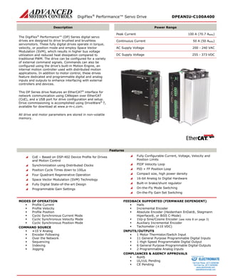
Power Range
The DigiFlex® Performance™ (DP) Series digital servo drives are designed to drive brushed and brushless servomotors. These fully digital drives operate in torque, velocity, or position mode and employ Space Vector Modulation (SVM), which results in higher bus voltage utilization and reduced heat dissipation compared to traditional PWM. The drive can be configured for a variety of external command signals. Commands can also be configured using the drive’s built-in Motion Engine, an internal motion controller used with distributed motion applications. In addition to motor control, these drives feature dedicated and programmable digital and analog inputs and outputs to enhance interfacing with external controllers and devices.
This DP Series drive features an EtherCAT® interface for network communication using CANopen over EtherCAT (CoE), and a USB port for drive configuration and setup. Drive commissioning is accomplished using DriveWare® 7, available for download at www.a-m-c.com.
All drive and motor parameters are stored in non-volatile memory.
Peak Current 100 A (70.7 ARMS)
Continuous Current 50 A (50 ARMS)
AC Supply Voltage 200 - 240 VAC
DC Supply Voltage 255 - 373 VDC
Features
CoE – Based on DSP-402 Device Profile for Drives and Motion Control
Synchronization using Distributed Clocks
Position Cycle Times down to 100μs
Four Quadrant Regenerative Operation
Space Vector Modulation (SVM) Technology
Fully Digital State-of-the-art Design
Programmable Gain Settings
Fully Configurable Current, Voltage, Velocity and Position Limits
PIDF Velocity Loop
PID + FF Position Loop
Compact size, high power density
16-bit Analog to Digital Hardware
Built-in brake/shunt regulator
On-the-Fly Mode Switching
On-the-Fly Gain Set Switching
MODES OF OPERATION
Profile Current
Profile Velocity
Profile Position
Cyclic Synchronous Current Mode
Cyclic Synchronous Velocity Mode
Cyclic Synchronous Position Mode
COMMAND SOURCE
±10 V Analog
Encoder Following
Over the Network
Sequencing
Indexing
Jogging
FEEDBACK SUPPORTED (FIRMWARE DEPENDENT)
Halls
Incremental Encoder
Absolute Encoder (Heidenhain EnDat®, Stegmann Hiperface®, or BiSS C-Mode)
1Vp-p Sine/Cosine Encoder (see note 8 on page 3)
Auxiliary Incremental Encoder
Tachometer (±10 VDC)
INPUTS/OUTPUTS
1 Motor Thermistor/Switch Input
11 General Purpose Programmable Digital Inputs
1 High Speed Programmable Digital Output
6 General Purpose Programmable Digital Outputs
2 Programmable Analog Inputs
COMPLIANCES & AGENCY APPROVALS
RoHS
UL/cUL Pending
CE Pending
ELECTROMATE
Toll Free Phone (877) SERVO98
Toll Free Fax (877) SERV099
www.electromate.com
sales@electromate.com
Sold & Serviced By:
2. DigiFlex® Performance™ Servo Drive DPEANIU-C100A400
BLOCK DIAGRAM
DC+ MOTOR AMOTOR BMOTOR CDC- POWER MODULEPower StageL1L2BRLOGIC+ LOGIC– Logic PowerShunt Reg. L3PAI-1 + (REF+) PAI-1 – (REF–) TD+ TD- I/O InterfaceI/O Interface DriveLogicEtherCAT InterfaceCONTROL MODULE10k+5V10k20k20k20kMOTOR THERMISTOR/ SWITCHDATA- DATA+ GNDAUX ENC A,B,-) USB InterfaceRD+ RD- VBUSAUX ENC A,B,I+ 10k+5VPDI-1,2,3,4(GENERAL PURPOSE) IN COMMON (1-4) 2.5KPDO-1,2,3,4,5,6OUT COMMON (1-6) PDI-5,6,7(GENERAL PURPOSE) IN COMMON (5-7) 2.5KPDI-8,9,10,11(GENERAL PURPOSE) IN COMMON (8-11) 2.5KENC A,B,I + / SIN+ / COS+ / REF MARK+ ENC A,B,I – / SIN- / COS- / REF MARK- HALL A,B,C + / DATA,CLOCK+ HALL A,B,C – / DATA,CLOCK- +5V+5V+5V Motor Feedback ENC A,B,I + OUTENC A,B,I – OUTPAI-2SGN GND33kHS PDO-7
Information on Approvals and Compliances
RoHS (Reduction of Hazardous Substances) is intended to prevent hazardous substances such as lead from being manufactured in electrical and electronic equipment.
ELECTROMATE
Toll Free Phone (877) SERVO98
Toll Free Fax (877) SERV099
www.electromate.com
sales@electromate.com
Sold & Serviced By:
3. DigiFlex® Performance™ Servo Drive DPEANIU-C100A400
SPECIFICATIONS
Power Specifications
Description
Units
Value
Rated Voltage
VAC (VDC)
240 (339)
AC Supply Voltage Range
VAC
200 - 240
AC Supply Minimum
VAC
180
AC Supply Maximum
VAC
264
AC Input Phases1
-
3
AC Supply Frequency
Hz
50 – 60
DC Supply Voltage Range2
VDC
255 - 373
DC Bus Over Voltage Limit
VDC
420
DC Bus Under Voltage Limit
VDC
205
Logic Supply Voltage
VDC
20 - 30 (@ 1 A)
Maximum Peak Output Current3
A (ARMS)
100 (70.7)
Maximum Continuous Output Current4
A (ARMS)
50 (50)
Maximum Continuous Power @ Rated Voltage5
W
16103
Maximum Continuous Power Dissipation @ Rated Voltage
W
848
Internal Bus Capacitance
μF
1120
External Shunt Resistor Minimum Resistance6
Ω
25
Minimum Load Inductance (Line-To-Line)7
μH
600
Switching Frequency
kHz
10
Maximum Output PWM Duty Cycle
%
100
Low Voltage Supply Outputs
-
+5 VDC (250 mA)
Control Specifications
Description
Units
Value
Communication Interfaces8
-
EtherCAT® (USB for Configuration)
Command Sources
-
±10 V Analog, Encoder Following, Over the Network, Sequencing, Indexing, Jogging
Feedback Supported9
-
Halls, Incremental Encoder, Absolute Encoder (Heidenhain EnDat®, Stegmann Hiperface®, or BiSS C-Mode), 1Vp-p Sine/Cosine Encoder, Auxiliary Incremental Encoder, Tachometer (±10 VDC)
Commutation Methods
-
Sinusoidal, Trapezoidal
Modes of Operation
-
Profile Current, Profile Velocity, Profile Position, Cyclic Synchronous Current, Cyclic Synchronous Velocity, Cyclic Synchronous Position
Motors Supported
-
Closed Loop Vector, Single Phase (Brushed, Voice Coil, Inductive Load), Three Phase (Brushless)
Hardware Protection
-
40+ Configurable Functions, Over Current, Over Temperature (Drive & Motor), Over Voltage, Short Circuit (Phase-Phase & Phase-Ground), Under Voltage
Programmable Digital Inputs/Outputs (PDIs/PDOs)
-
11/7
Programmable Analog Inputs/Outputs (PAIs/PAOs)
-
2/0
Primary I/O Logic Level
-
24 VDC
Current Loop Sample Time
μs
100
Velocity Loop Sample Time
μs
200
Position Loop Sample Time
μs
200
Maximum Sin/Cos Encoder Frequency
kHz
200
Maximum Sin/Cos Interpolation
-
2048 counts per sin/cos cycle
Internal Shunt Regulator
-
Yes
Internal Shunt Resistor
-
No
Mechanical Specifications
Description
Units
Value
Agency Approvals
-
RoHS, UL/cUL Pending, CE Pending
Size (H x W x D)
mm (in)
256.5 x 182.6 x 135.3 (10.1 x 7.2 x 5.3)
Weight
g (oz)
3560.7 (125.6)
Heatsink (Base) Temperature Range10
°C (°F)
0 - 75 (32 - 167)
Storage Temperature Range
°C (°F)
-40 - 85 (-40 - 185)
Cooling System
-
Forced Convection
Form Factor
-
Panel Mount
AUX. COMM Connector
-
5-pin, Mini USB B Type port
COMM Connector
-
Shielded, dual RJ-45 socket with LEDs
FEEDBACK Connector
-
15-pin, high-density, female D-sub
AUX. ENCODER Connector
-
15-pin, high-density, male D-sub
I/O Connector
-
26-pin, high-density, female D-sub
+24V LOGIC Connector
-
2-port, 5.08 mm spaced, enclosed, friction lock header
FAN Connector
-
2-port, 5.08 mm spaced, enclosed, friction lock header
MOTOR POWER Connector
-
4-port, 10.16 mm spaced, enclosed, friction lock header
AC POWER Connector
-
4-port, 10.16 mm spaced, enclosed, friction lock header
DC POWER Connector
-
4-port, 10.16 mm spaced, enclosed, friction lock header
1. Can operate on single-phase AC (208 VAC minimum) as long as output power does not exceed 3kW maximum. Current limits are de-rated to 30A cont. / 60A peak.
2. Large inrush current may occur upon initial DC supply connection to DC Bus.
3. Capable of supplying drive rated peak current for 2 seconds with 10 second foldback to continuous value. Longer times are possible with lower current limits.
4. Continuous Arms value attainable when RMS Charge-Based Limiting is used.
5. P = (DC Rated Voltage) * (Cont. RMS Current) * 0.95
6. ADVANCED Motion Controls recommends using an external fuse in series with the shunt resistor. A 5 amp motor delay fuse is typical.
7. Lower inductance is acceptable for bus voltages well below maximum. Use external inductance to meet requirements.
8. EtherCAT® is a registered trademark and patented technology, licensed by Beckhoff Automation GmbH, Germany.
9. Contact ADVANCED Motion Controls for 1Vp-p Sine/Cosine Encoder feedback availability.
10. Additional cooling and/or heatsink may be required to achieve rated performance.
ELECTROMATE
Toll Free Phone (877) SERVO98
Toll Free Fax (877) SERV099
www.electromate.com
sales@electromate.com
Sold & Serviced By:
4. DigiFlex® Performance™ Servo Drive DPEANIU-C100A400
PIN FUNCTIONS
COMM – EtherCAT Communication Connector
Pin
Name
Description / Notes
I/O
1
RD+
Receiver + (100Base-TX)
I
2
RD-
Receiver - (100Base-TX)
I
3
TD+
Transmitter + (100Base-TX)
O
4
RESERVED
-
-
5
RESERVED
-
-
6
TD-
Transmitter - (100Base-TX)
O
7
RESERVED
-
-
8
RESERVED
-
-
9
RESERVED
-
-
I/O – Signal Connector
Pin
Name
Description / Notes
I/O
1
PDO-1
General Purpose Programmable Digital Output (120 mA maximum)
O
2
PDO-2
General Purpose Programmable Digital Output (120 mA maximum)
O
3
PDO-3
General Purpose Programmable Digital Output (120 mA maximum)
O
4
OUT COMMON
Digital Output Common (1-6)
OCOM
5
GROUND
Ground
GND
6
PDO-4
General Purpose Programmable Digital Output (120 mA maximum)
O
7
PDO-5
General Purpose Programmable Digital Output (120 mA maximum)
O
8
HS PDO-7
High Speed Programmable Digital Output
O
9
PDO-6
General Purpose Programmable Digital Output (120 mA maximum)
O
10
PDI-1
General Purpose Programmable Digital Input
I
11
PDI-2
General Purpose Programmable Digital Input
I
12
PDI-3
General Purpose Programmable Digital Input
I
13
PDI-4
General Purpose Programmable Digital Input
I
14
IN COMMON
Digital Input Common (1-4)
ICOM
15
IN COMMON
Digital Input Common (5-7)
ICOM
16
PDI-5
General Purpose Programmable Digital Input
I
17
PDI-6
General Purpose Programmable Digital Input
I
18
PDI-7
General Purpose Programmable Digital Input
I
19
PDI-8
General Purpose Programmable Digital Input
I
20
PDI-9
General Purpose Programmable Digital Input
I
21
PDI-10
General Purpose Programmable Digital Input
I
22
PDI-11
General Purpose Programmable Digital Input
I
23
IN COMMON
Digital Input Common (8-11)
ICOM
24
PAI-1+
General Purpose Differential Programmable Analog Input
I
25
PAI-1-
I
26
GROUND
Ground
GND
FEEDBACK – Feedback Connector *
Pin
Incremental Encoder
Absolute Encoder
1Vp-p Sin/Cos Encoder
Description / Notes
I/O
1
HALL A+
DATA-
HALL A+
Differential Hall A+/ Differential Data Line
I
2
HALL B+
CLOCK+
HALL B+
Differential Hall B+ / Differential Clock Line
I
3
HALL C+
N/C
HALL C+
Differential Hall C+
I
4
ENC A+
SIN +
SIN +
Differential Encoder A / Differential Sine Input
I
5
ENC A-
SIN -
SIN -
I
6
ENC B+
COS +
COS +
Differential Encoder B/ Differential Cosine Input
I
7
ENC B-
COS -
COS -
I
8
ENC I+
REF MARK+
REF MARK +
Differential Encoder Index / Differential Reference Mark
I
9
ENC I-
REF MARK-
REF MARK -
I
10
HALL A-
DATA+
HALL A-
Differential Hall A- / Differential Data Line
I
11
HALL B-
CLOCK-
HALL B-
Differential Hall B- / Differential Clock Line
I
12
SGND
SGND
SGND
5V Return (Signal Ground)
SGND
13
+5V OUT
+5V OUT
+5V OUT
+5V Encoder Supply Output. Short-circuit protected. (250mA)
O
14
THERMISTOR
THERMISTOR
THERMISTOR
Motor Thermal Protection
I
15
HALL C-
N/C
HALL C-
Differential Hall C-.
I
*Note: Feedback supported (Incremental Encoder, Absolute Sin/Cos Encoder, or 1Vp-p Sin/Cos Encoder) will be dependent on firmware. Contact ADVANCED Motion Controls for 1Vp-p Sin/Cos Encoder feedback availability.
ELECTROMATE
Toll Free Phone (877) SERVO98
Toll Free Fax (877) SERV099
www.electromate.com
sales@electromate.com
Sold & Serviced By:
5. DigiFlex® Performance™ Servo Drive DPEANIU-C100A400
AUX. ENCODER – Auxiliary Encoder Connector
Pin
Name
Description / Notes
I/O
1
ENC A+ OUT
Emulated Encoder Channel A Output
O
2
ENC A- OUT
O
3
ENC B+ OUT
Emulated Encoder Channel B Output
O
4
AUX ENC A+
Auxiliary Encoder Input (For single ended signal leave negative terminal open)
I
5
AUX ENC A-
I
6
AUX ENC B+
Auxiliary Encoder Input (For single ended signal leave negative terminal open)
I
7
AUX ENC B-
I
8
AUX ENC I+
Auxiliary Encoder Index Input (For single ended signal leave negative terminal open)
I
9
AUX ENC I-
I
10
ENC B- OUT
Emulated Encoder Channel B Output
O
11
ENC I+ OUT
Emulated Encoder Index Output
O
12
SGND
Signal Ground
SGND
13
+5V OUT
+5 VDC User Supply
O
14
PAI-2
Programmable Analog Input (12-bit Resolution)
I
15
ENC I- OUT
Emulated Encoder Index Output
O
AUX. COMM - USB Communication Connector
Pin
Name
Description / Notes
I/O
1
VBUS
Supply Voltage
O
2
DATA -
Data -
I/O
3
DATA +
Data +
I/O
4
RESERVED
-
-
5
USB GND
USB Ground
UGND
Logic Power Connector
Pin
Name
Description / Notes
I/O
1
LOGIC GND
Logic Supply Ground
SGND
2
LOGIC PWR
Logic Supply Input
I
Fan Power Connector
Pin
Name
Description / Notes
I/O
1
FAN GND
Fan Ground
GND
2
FAN PWR
Fan Power Input
I
Motor Power Connector
Pin
Name
Description / Notes
I/O
1
CHASSIS
Chassis Ground
CGND
2
MOTOR A
Motor Phase A
O
3
MOTOR B
Motor Phase A
O
4
MOTOR C
Motor Phase B
O
AC Power Connector
Pin
Name
Description / Notes
I/O
1
L1
AC Supply Input (Three Phase). External 20 A time delay fuses are recommended in series with the AC input lines.
I
2
L2
I
3
L3
I
4
CHASSIS
Chassis Ground
CGND
DC Power Connector
Pin
Name
Description / Notes
I/O
1
DC-
Power Ground
PGND
2
DC+
DC Power Input
I
3
DC+
External Shunt Resistor Connection. Connect resistor between DC+ and BR.
-
4
BR
- ELECTROMATE
Toll Free Phone (877) SERVO98
Toll Free Fax (877) SERV099
www.electromate.com
sales@electromate.com
Sold & Serviced By:
6. DigiFlex® Performance™ Servo Drive DPEANIU-C100A400
HARDWARE SETTINGS
EtherCAT Station Alias Selector Switches
Switch Diagram
Description
0123 456789ABCDEF 0123 456789ABC DEF SW1SW0
Hexadecimal switch settings correspond to the drive Station Alias. Note that drives on an EtherCAT network will be given an address automatically based on proximity to the host. Setting the switches manually is optional, and only necessary if a fixed address is required.
SW1
SW0
Node ID
0
0
000
0
1
001
0
2
002
…
…
…
F
D
253
F
E
254
F
F
255
LED Functions (on RJ-45 Communication Connectors)
LINK LED
LED State
Description
Green – On
Valid Link - No Activity
Green – Flickering
Valid Link - Network Activity
Off
Invalid Link
STATUS LED
LED State
Description
Green – On
The device is in the state OPERATIONAL
Green – Blinking (2.5Hz – 200ms on and 200ms off)
The device is in the state PRE-OPERATIONAL
Green – Single Flash (200ms flash followed by 1000ms off)
The device is in state SAFE-OPERATIONAL
Green – Flickering (10Hz – 50ms on and 50ms off)
The device is booting and has not yet entered the INIT state
or
The device is in state BOOTSTRAP
or
Firmware download operation in progress
Off
The device is in state INIT
ERROR LED
LED State
Description
Example
Red – On
A PDI Watchdog timeout has occurred.
Application controller is not responding anymore.
Red – Blinking (2.5Hz – 200ms on and 200ms off)
General Configuration Error.
State change commanded by master is impossible due to register or object settings.
Red – Flickering (10Hz – 50ms on and 50ms off)
Booting Error was detected. INIT state reached, but parameter “Change” in the AL status register is set to 0x01:change/error
Checksum Error in Flash Memory.
Red – Single Flash (200ms flash followed by 1000ms off)
The slave device application has changed the EtherCAT state autonomously: Parameter “Change” in the AL status register is set to 0x01:change/error.
Synchronization error; device enters SAFE- OPERATIONAL automatically
Red – Double Flash (Two 200ms flashes separated by 200ms off, followed by 1000ms off)
An application Watchdog timeout has occurred.
Sync Manager Watchdog timeout.
ELECTROMATE
Toll Free Phone (877) SERVO98
Toll Free Fax (877) SERV099
www.electromate.com
sales@electromate.com
Sold & Serviced By:
7. DigiFlex® Performance™ Servo Drive DPEANIU-C100A400
MECHANICAL INFORMATION
COMM - EtherCAT Communication Connector
Connector Information
Shielded, dual RJ-45 socket with LEDs
Mating Connector
Details
Standard CAT 5e or CAT 6 ethernet cable
Included with Drive
No
RD+1TD+3RD+13INOUTTD+ RD-2TD-66TD- 2RD- LINKLINKSTATUSERROR
I/O - Signal Connector
Connector Information
26-pin, high-density, female D-sub
Mating Connector
Details
TYCO: Plug P/N 1658671-1; Housing P/N 5748677-3; Terminals P/N 1658670-2 (loose) or 1658670-1 (strip)
Included with Drive
No
PDO-1123456897IN COMMON14PDI-211PDI-312PDI-413PDI-110IN COMMON15PDI-617PDI-718PDI-516PDO-2PDO-6HS PDO-7PDO-5PDO-4HS OUT COMMONOUT COMMONPDO-3PDI-819PDI-1122PDI-920PDI-1021GROUND26PAI-1-2524PAI-1+ 23IN COMMON
FEEDBACK - Feedback Connector
Connector Information
15-pin, high-density, female D-sub
Mating Connector
Details
TYCO: Plug P/N 748364-1; Housing P/N 5748677-2; Terminals P/N 1658670-2 (loose) or 1658670-1 (strip)
Included with Drive
No
HALL A+1HALL B+2HALL C+3ENC A+4ENC A-5HALL B-11SGND12+5V OUT13THERMISTOR14HALL C-15ENC B+6HALL A-10ENC B-7ENC I+8ENC I-9DATA-1CLOCK+2N/C3SIN+4SIN-5CLOCK-11SGND12+5V OUT13THERMISTOR14N/C15COS+6DATA+10COS-7REF MARK+8REF MARK-9HALL A+1HALL B+2HALL C+3SIN+4SIN-5HALL B-11SGND12+5V OUT13THERMISTOR14HALL C-15COS+6HALL A-10COS-7REF MARK+8REF MARK-9
Incremental Encoder Absolute Encoder 1Vp-p Sin/Cos Encoder
ELECTROMATE
Toll Free Phone (877) SERVO98
Toll Free Fax (877) SERV099
www.electromate.com
sales@electromate.com
Sold & Serviced By:
8. DigiFlex® Performance™ Servo Drive DPEANIU-C100A400
AUX. ENCODER - Auxiliary Feedback Connector
Connector Information
15-pin, high-density, male D-sub
Mating Connector
Details
TYCO: Plug P/N 1658681-1; Housing P/N 5748677-2; Terminals P/N 1658686-2 (loose) or 1658686-1 (strip)
Included with Drive
No
AUX ENC A-5AUX ENC A+4ENC B+ OUT3ENC A- OUT2ENC A+ OUT1ENC I- OUT15PAI-214+5V OUT13SGND12ENC I+ OUT11ENC B- OUT10AUX ENC B+6AUX ENC I-9AUX ENC I+8AUX ENC B-7
AUX. COMM – USB Communication Connector
Connector Information
5-pin, Mini USB B Type port
Suggested Mating Cable
Details
TYCO: 1496476-3 (2-meter STD-A to MINI-B ASSY)
Included with Drive
No
1VBUS2DATA - 3DATA + 4RESERVED5USB GND
Logic Power Connector
Connector Information
2-port, 5.08 mm spaced, enclosed, friction lock header
Mating Connector
Details
Phoenix Contact: P/N 1757019
Included with Drive
Yes
1LOGIC GND2LOGIC PWR
Fan Power Connector
Connector Information
2-port, 5.08 mm spaced, enclosed, friction lock header
Mating Connector
Details
Phoenix Contact: P/N 1757019
Included with Drive
Yes
1FAN GND2FAN PWR
ELECTROMATE
Toll Free Phone (877) SERVO98
Toll Free Fax (877) SERV099
www.electromate.com
sales@electromate.com
Sold & Serviced By:
9. DigiFlex® Performance™ Servo Drive DPEANIU-C100A400
Motor Power Connector
Connector Information
4-pin, 10.16 mm spaced, enclosed, friction lock header
Mating Connector
Details
Phoenix Contact: P/N 1913523
Included with Drive
Yes
CHASSIS1MOT A2MOT B3MOT C4
AC Power Connector
Connector Information
4-pin, 10.16 mm spaced, enclosed, friction lock header
Mating Connector
Details
Phoenix Contact: P/N 1913523
Included with Drive
Yes
L11L22L33CHASSIS4
DC Power Connector
Connector Information
4-pin, 10.16 mm spaced, enclosed, friction lock header
Mating Connector
Details
Phoenix Contact: P/N 1913523
Included with Drive
Yes
DC-1DC+2DC+3BR4
ELECTROMATE
Toll Free Phone (877) SERVO98
Toll Free Fax (877) SERV099
www.electromate.com
sales@electromate.com
Sold & Serviced By:
11. DigiFlex® Performance™ Servo Drive DPEANIU-C100A400
PART NUMBERING INFORMATION
C- Drive SeriesDigiFlex® Performance™ Panel MountCommunicationCommand InputsEPDINAU001A004Example: DPRS232/RS485RCANopen or RS232CEthernet Powerlink or TCP/IPPAnalog (±10V) No Step & DirectionANAnalog (±10V) Low Voltage Step & Direction (5V)ALAnalog (±10V) High Voltage Step & Direction (24V)AHNo AnalogLow Voltage Step & Direction (5V)NLNo Analog, No Step & Direction(Communication Interface Only)NNDigital I/OIsolated (24V)ITTL (5V) Non-IsolatedTMotor FeedbackIncremental Encoder and/or HallsEResolverRAbsolute Sin/Cos (Hiperface & Endat)ASin/Cos with HallsSMax DC Bus Voltage (VDC) 80080200200400400800800AC Input+24VDC User Logic Supply RequiredAAC Input Single Phase Only+24VDC User Logic Supply RequiredSDC InputBoth Logic Supply Options (Internal or User)BDC InputLogic Supply RequiredL15015160162002025025300304004060C060100C100- Code used to identify customer specialsPower and Logic SupplyPeak Current (A0 to Peak) Customer SpecialEtherCATEUniversal (Halls, Inc. Enc., Abs. Enc., 1Vp-p Sin/Cos Enc.)U60060
DigiFlex® Performance™ series of products are available in many configurations. Note that not all possible part number combinations are offered as standard drives. All models listed in the selection tables of the website are readily available, standard product offerings.
ADVANCED Motion Controls also has the capability to promptly develop and deliver specified products for OEMs with volume requests. Our Applications and Engineering Departments will work closely with your design team through all stages of development in order to provide the best servo drive solution for your system. Equipped with on-site manufacturing for quick- turn customs capabilities, ADVANCED Motion Controls utilizes our years of engineering and manufacturing expertise to decrease your costs and time-to-market while increasing system quality and reliability. Feel free to contact Applications Engineering for further information and details.
Examples of Customized Products
Optimized Footprint
Tailored Project File
Private Label Software
Silkscreen Branding
OEM Specified Connectors
Optimized Base Plate
No Outer Case
Increased Current Limits
Increased Current Resolution
Increased Voltage Range
Increased Temperature Range
Conformal Coating
Custom Control Interface
Multi-Axis Configurations
Integrated System I/O
Reduced Profile Size and Weight
Available Accessories
ADVANCED Motion Controls offers a variety of accessories designed to facilitate drive integration into a servo system.
Visit www.a-m-c.com to see which accessories will assist with your application design and implementation.
Power Supplies
Shunt Regulators
Drive(s)
Filter Cards
To Motor
All specifications in this document are subject to change without written notice. Actual product may differ from pictures provided in this document.
ELECTROMATE
Toll Free Phone (877) SERVO98
Toll Free Fax (877) SERV099
www.electromate.com
sales@electromate.com
Sold & Serviced By: