1. Robot Building Competition 2016
Tutorial 1: Computer Aided Design
Charling Li, Phillip Luu, Ashlee Pearson, Julian Wu
August 5, 2016
v2.15 (Final Release)
Abstract
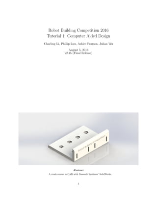
A crash course in CAD with Dassault Syst`emes’ SolidWorks.
1
2. 1 Prologue
The strength in CAD lies in its ability to convey ideas and concepts much more efficiently and perhaps more
effectively than traditional paper drawings. Being able to intuitively model something as it would look when
manufactured is a huge step up from traditional engineering drawings.
This rationale has gained traction in the real world through the development of software packages such
as SolidWorks and its widespread use in relevant industries. Therefore, my goal will be to try to provide an
intuitive, basic introduction to CAD for you all. Hopefully, by the end of this tutorial, you might develop
some small appreciation for the nuances of engineering drawings as they were. . . back in my day.
It’s worth mentioning here that this tutorial is not a be-all-end-all guide to CAD, nor is it an exhaus-
tive walkthrough on making a simple model (though I have tried!), nor is it even required for you to succeed
in this competition. If you see an easier, faster, simpler way to do things, I urge you to take it and report
back to me on your success. If you choose to design your own custom model, go for it. This is, first and
foremost, a learning experience for all of us, myself as one of the authors included.
2
3. 2 Fundamentals of CAD
2.1 Fundamentals of Engineering Drawings and CAD
2.1.1 Perspective
The most common demarcation of engineering drawings deals with how models are presented.
The two major types are:
Perspective: Perspective views are characterised by the decrease in the size of objects the further they
are from the viewer. While great for rendering realistic models, perspective views are terrible for
dimensioning (indicating lengths of edges and angles between lines) because relative lengths change
between objects.
Parallel: Parallel views are those that cannot be realistic, since they contain lines that are parallel along
more than one axis, meaning that a viewer would need to be standing an infinite distance away, with
infinitely good eyesight, to achieve these views. They are much better for dimensioning since lines are
of the same relative length, wherever they are on the drawing.
Inherently, we engineers are inclined to use parallel projection views because it’s easiest to convey information
using drawings where a line of a unit length looks the same at every point on the canvas. Thus, we’ve
developed a few different types of parallel projection to use as follows:
Oblique: Oblique views are some of the simplest 3D drawings. One face is chosen to be completely normal
to the camera, and features behind the face are angled away for depth to create a 3D representation.
Isometric: Isometric views are the most commonly accepted 3D representation since lines of unit length
in all directions (the ”iso” part of the name) look the same length (”metric”). This can, in fact, be
inferred from the name. This allows for quick dimensioning.
Orthogonal: Orthogonal views allow a 3D model to be represented in two dimensions using a series of views
looking directly along coordinate axes into the model. This allows for comprehensive dimensioning,
and for this reason, is universally used in drawings.
You’ll find that SolidWorks is very flexible when dealing with perspective, allowing you to find a view that’s
most comfortable to work in depending on the immediate task.
3
4. 2.2 Fundamentals of SolidWorks
We now know enough to jump right into the program, and start turning a 2D idea into a 3D model.
When you first open the program (and sit through the pretty showcase of models done by professionals),
you will be presented with a blank splash screen. Opening a new file will prompt you with a screen asking
for a part, an assembly, or a drawing.
Part: A part is a single component that requires its own dimensions to be defined.
Assembly: An assembly is a collection of parts mated to create a comprehensive model.
Drawing: Drawings are 2D renderings of parts or assemblies for print purposes.
Let’s open a new part.
Figure 1: The working area of a new part in SolidWorks.
The first few things you’ll see in the working area of the program are detailed in the following sections.
2.2.1 The Features Toolbar
This area contains all the major features necessary to create a model. Creating a 2D sketch and using that
sketch to extrude a prism are the two fundamental commands used in the creation of a model. Pressing
Alt will bring up the menu bar above the Features Toolbar, which has more options for sketch and model
manipulation.
2.2.2 The Property Manager
This area contains details and properties about the feature being edited, and allows customisation of dimen-
sions, options and materials.
4
5. 2.2.3 The Perspective Bar
This area allows for models to be viewed in any perspective, cross-sections to be viewed, and materials to
be assigned. For the most part, we will be working with this layout here, so take a couple of moments to
familiarize yourself with the different tabs in the Features Toolbar, the options in the Property Manager,
and explore a bit to get comfortable with where everything is.
For more practice, navigate through the Menu Bar to Help - SolidWorks Tutorials. There
are invaluable resources built-in to the Student edition to assist you with features and functions.
In this tutorial, we will use the direct-modelling method of CAD, where every feature is created visually
from a sketch, then projected into a third dimension. This is contrasted with the parametric method, where
features are created parametrically, using commands and equations. SolidWorks is capable of parametric
CAD, and I could go into a whole chapter on the advantages and disadvantages of either approach, but for
now, we will focus on direct modelling as it is simpler to use for beginner pupils.
5
6. 3 Practical CAD Direct-Modelling
The following will be a step-by-step walkthrough of the process necessary to create a CAD model of a sensor
mount.
3.1 Extruding a Base
1. Starting a new model
Start by creating a new part.
You should see a blank screen as shown in Figure 1.
2. Creating a new sketch
In the Features Toolbar, select the Sketch Tab, then click Sketch.
You should see three planes appear as the base for the sketch.
You can choose any plane you like - all this changes is the direction in which the part is oriented. For
the sake of simplicity, I will choose the Top Plane.
3. Creating simple geometry
Select the Centre Rectangle, then create a rectangle centred at the origin of any size.
If you mouse over the red arrows denoting the directions of the axes on the plane, an orange dot should
appear denoting the origin, and the cursor should show a yellow icon with two intersecting lines joined
6
7. by a green dot.
Your rectangle can be of any size; we’ll be dimensioning (setting the lengths) in the next step.
4. Dimensioning geometry
Next to Exit Sketch, click Smart Dimension, then click on either of the vertical rectangle sides. Click
anywhere in the working area, then set the length in the popup to 84mm. Click OK.
You should notice the two horizontal sides turn black. This is to signify that they now have enough
information to be fully defined parts of the sketch - i.e. their lengths and positions are unambiguous.
5. Fully defining the sketch
Similarly, set the width of the rectangle to 64mm. Your rectangle should now look like Figure 2.
Figure 2: The base sketch for the mount.
6. Extruding a base
Click Exit Sketch, and you should see the sketch turn grey, and the Features Toolbar should show the
Features Tab. Click Extruded Boss/Base, then click on the sketch.
7
8. We have just begun the process of turning a 2D sketch into a 3D model!
7. Extruding a base
In the Property Manager, set the extrusion type to Blind and the depth to 25.50mm.
This fully dimensions the rectangular prism we’ll be using as a base for the mount shape.
8. Viewing perspectives
Your model should look like Figure 3 if your perspective is set to isometric view.
Figure 3: The base prism for the model.
You can use the Perspective Bar to view different angles and to find a perspective that is comfortable
for you.
8
9. 3.2 Creating a Cut
9. Sketching onto faces
Having a rectangular block is impressive; much more than you were able to do half an hour ago, but
it’s not exactly going to cut it in this competition.
In the Features Toolbar, click Extruded Cut, then (after switching to Left view) click on the left face
of the rectangular prism.
Nothing will change about the view if you’re in isometric perspective, so it may be helpful at this point
to select a view from the Perspective Bar that projects the left face orthogonally.
10. More simple geometry
Select the Corner Rectangle, then create a rectangle along the left, top and right edges of the face.
Move your cursor until an orange dotted line shows up along the top-left corner - this will ensure your
rectangle is lined up properly.
Make sure your sketch looks like the one below!
11. More Smart Dimensioning
Using the Smart Dimension tool, click on the bottom edge of the face, then the top edge of the lower
rectangle and dimension the distance to 5mm.
12. Creating the cut
Click Exit Sketch, and in the Property Manager, set the cut type to Blind, and the depth to 59mm.
Click OK.
13. Checkpoint!
Your model should look like Figure 4.
Figure 4: The prism with the extruded cut to slot onto the baseboard.
9
10. 3.3 Making Screw Holes
14. Using the Hole Wizard
Our next task is to create holes for screws to attach this mount onto the baseboard.
Next to the Extruded Cut button, you’ll find the Hole Wizard. Click on it.
Of course, we could use our own sketch to create holes for screws, and dimension them ourselves. . . but
it’s just much cooler (and perhaps easier, faster, and simpler) this way.
15. Choosing a Hole
We would like to create a hole for a counterbored, mushroom-headed M3 (this is an AS-defined
dimension that determines the pitch and diameter of a screw hole) screw. We want this hole to go
through only the top region, so set the end condition to Up To Next, which will stop it at the next
boundary. Once you’ve selected these properties in the Property Manager, position the screw anywhere
on the top face by switching to the Positions Tab in the Property Manager and following the prompts.
You may find it helpful to switch back to an orthogonal view using the Perspective Bar.
16. Creating a Reference Line
Our objective now is to have four such screw holes equally spaced along the top. We do this by using
a centerline, which can be accessed through the Sketch tab in the Features Toolbar. Make a vertical
10
11. centerline from the center of the hole (coincident with the point) straight down without touching the
bottom edge of the face.
This line does not directly contribute as a boundary for a feature, but will guide our geometry.
17. Even more Smart Dimensioning
Dimension the centerline so that it is 12mm from the top and bottom edges of the face, and 20mm
from the left edge of the face. Exit the Sketch.
18. Viewing sketches outside of features
To show our sketch even though it’s linked to its own feature, expand the feature in the Property
Manager, right-click the latest sketch, and click on the glasses icon (the Show icon). We’ll need this
for the next step.
11
12. 19. Creating a curve-driven pattern
With the sketch in grey selected, navigate to the Menu Bar, and click Insert - Pattern/Mirror -
Curve Driven Pattern. . .
20. Specifying the pattern
In the Property Manager, the direction should automatically be defined as the centerline. If not, click
the blank box, then the grey centerline. Set the number of instances to 4. Tick Equal Spacing.
Click the blank box in the Features to Pattern drop-down panel, then click on the hole feature we just
created. Click OK.
Note that the features list actually pops out into the working area to make it easier to use. You may
need to expand the drop-down list under the part so that the hole feature is visible.
21. Nice work!
Your model should now look like Figure 5.
12
13. Figure 5: The prism is looking more like a mount, now.
13
14. 3.4 Making Colour Sensor Slots
22. Creating a reference sketch
We now want to make holes in which sensors can be mounted. Colour sensors will be used to detect
the colour of the gates along the track. Take a look at Figures 6 and 7 for an example of what the
sensors would look like. We’ll be mounting them using the pins at the back.
Figure 6: Top and bottom views of the colour sensor.
Open a sketch onto the right face, create a horizontal centerline slightly offset from the middle of the
face, and make sure it spans the width of the face. Similarly create a vertical centerline spanning the
height, directly across the center of the face.
You may find it helpful to make use of the automatic snap-to guides alluded to in Step 3.
23. Creating a base sketch
In the same sketch, create a center rectangle with an origin about the horizontal centerline. Dimension
its width to be 2.80mm, height 10.40mm. Dimension the distance from the left edge of the face to
the left side of the rectangle to be 5mm, and the distance from the bottom edge to the bottom side
to be 5mm.
14
15. 24. Patterning the holes
Select the rectangle by clicking and dragging across the shape, then click on the Linear Sketch Pattern
button in the Features Toolbar. In the Property Manager, choose the distance to the patterned sketch
to be 27.70mm towards the vertical centerline. Click OK.
You’ll notice a ’2’ pop up on the sketch. Don’t worry, it simply indicates the number of instances
you’ve patterned.
25. Mirroring the sketch
Click Mirror Entities with both rectangles selected. In the Mirror About box, select the vertical
centerline, and press OK.
Your selection should be highlighted in light blue. It doesn’t matter if you include your centerlines.
26. Making the cut
Exit the sketch, and with it selected, create an Extruded Cut. Select the cut type to be Up To Next
and click OK.
27. Almost there!
Indeed you are. Check that your model looks like the one below in Figure 7.
Figure 7: It is now possible to mount colour sensors on the right face.
15
16. 3.5 Making IR Sensor Slots
28. Creating a reference sketch
The final step in making the mount functional is to add slots for IR sensors. These will be used to
detect the line under the robot and correct its movement. Figure 8 shows a sample IR sensor. We’ll
be mounting them using screws through the two 3mm diameter holes.
Figure 8: Top and bottom views of the IR sensor.
Open a sketch onto the top, create a vertical centerline offset from the middle, and make sure it spans
the height of the face. Similarly create a horizontal centerline. As you may have guessed, we’ll be
using this to guide the position of the screw holes.
29. Creating a base sketch
In the same sketch, create a circle centered on the centerline. Set its diameter to be 3mm and distance
from the top edge 16mm.
16
17. 30. Patterning the sketch
Similarly to the way we made the holes for the colour sensors, create a Linear Pattern along the vertical
centerline, and position the second circle 10mm towards the horizontal centerline.
31. Mirroring the holes
This time, you’ll be mirroring the two circles about the horizontal centerline.
32. Making the cut
Exit the sketch, and create an Up To Next-type Extruded Cut.
33. Congratulations!
Check that your model looks like the one below in Figure 9. If so, you’re done - you now have
everything necessary for the mount to work properly.
Figure 9: Awesome. The mount is now functionally complete! The top face has been highlighted to show
the cuts.
You can now get a volunteer to check over your model. Once it’s verified, save the SolidWorks file and
upload it to Moodle. It will then be turned into a 3D-printed part for your robot.
Alternatively, if you don’t like the design, feel free to CAD up your own! Just be wary of dimension
restrictions.
17
18. 3.6 Further Challenges
. . . You’re still here? Looking for more CAD? Sweet.
34. Filleting
Want nice, round curves or neat corners on your mount? Have a play around with the Fillet/Chamfer
feature.
Just make sure you don’t set the radius of the fillet/chamfer greater than the allowable size of an end
(e.g. don’t attempt to create a 5mm fillet on the corner of a section that’s only 3mm thick.), and
avoid filleting corners/onto surfaces that will come into contact with other parts, as this can mess with
the tolerancing of the part.
35. Text
If you’d like to add a team name (or other text) to your model, you can do this through the use of text
in the Sketch tab of the Features Toolbar. You can then either extrude a boss or a cut in the shape of
the text.
To make it easier, create a centerline along which you’d like the text, then position the text on that
centerline.
It is possible to use curved lines to guide the text.
Please avoid fancy fonts. The more complex a geometry, the more time it takes to print something
and the less legible it becomes. Legit though, it’s annoying.
36. Material and Appearance
For more detailed analysis/rendering, it is possible to specify the material from which the model is
made. In SolidWorks, this will only change the aesthetic of the model, but it can then be analysed for
specific weight and geometry properties, and rendered for presentation purposes.
You can find the material selection in the Property Manager when you have deselected everything in
the working area.
18
19. 4 Epilogue
Congratulations on making it through the tutorial successfully! You’ve done everything necessary to model
a working sensor mount, and after you submit your file through Moodle, it’ll be 3D-printed. Remember to
thank the volunteers before you leave!
If you have any feedback, direct it to us on the Robot Building Competition Facebook event page, or privately
at cli117@student.monash.edu.
4.1 Submissions
Your submissions will be due on the Moodle page at 2355, Sunday 7th
AUG 2016. Please observe the
following rules:
1. We will not be able to accept late submissions without an email to one of the organisers, as 3D printing
takes time, and we need to allocate enough for you to receive your parts in time.
2. Custom models are allowed, however, beware of a few restrictions:
- Dimensions: The mount must be no larger than 100mm by 100mm by 40mm.
- Mounting: You must keep the four M3 screw holes spaced 20mm apart in order to connect onto
the baseboard.
- Layout: For best results, only change the spacing between the pairs of sensor slots to customise
your mount. More details can be found below.
3. Note that if you want to attempt the bonus objective, you will want to design your mount such that
one of the colour sensors are facing downwards (to detect the colour of the lines) as an extension task.
4.2 Dimensions
Relevant dimensions for customisation of sensor mount are included here:
- Baseboard: This is the part onto which the sensor mount will be attached. 4 M3 screws will be used
to hold the sensor mount in place along the short edge.
Maximum dimensions: 200mm by 100mm by 3mm.
- Colour Sensor: Each team is allocated two of these sensors. No screw holes are present for the sensors
to mount, thus slots have been used to hold the sensors in place by their pins.
Maximum dimensions: 30.50mm by 24.20mm by 9.60mm.
Pin dimensions: 2.80mm by 10.40mm by 8.40mm.
Distance between pins (center-to-center): 27.70mm.
- IR Sensor: Each team is allocated two of these sensors. 2 M3 screw holes are used to attach the sensor
to the mount.
Maximum dimensions: 20mm by 20mm by 2.40mm.Distance between screw holes: 10mm.
As stated above, keep in mind that the above dimenions are fixed. You can change the positions of sensors,
but you will want to keep the orientation and general shape the same. By all means, customise and explore,
but do check with a volunteer or organiser if you want to print a custom model.
19
20. 5 Appendices
5.1 Resources and Further Reading
A free copy of SolidWorks is available from the Engineering Computer Labs as an .iso file. This comes with
a valid license key, so if you’d like to work on this tutorial at home, definitely check it out.
Note that if you would like to obtain a copy of SolidWorks, download the 2014/2015 edition; the Engineering
Computer Labs do not yet have 2015/2016 edition installed, with a couple of backwards-compatibility issues.
The link to the ECMS file hub is here: http://www.eng.monash.edu.au/ecms/software.html
Another resource to consider would be the SolidWorks tutorials. While less directed than this one, it
provides a solid foundation for the basics just as well.
For more on 3D printing, CAD, or the competition, ask any of our volunteers.
5.2 Further Thanks
In the course of writing this tutorial, I received invaluable feedback from the other members of the Robot
Building Competition 2016 organising team. Thank you to all the organisers for your support.
I need to thank the volunteer demonstrators in the tutorials for their time and efforts in assisting with the
effective delivery of this tutorial. We are truly grateful on behalf of the organising team and the participants.
Special thanks must also go to Lahiru Bandara, Vincent He and Nhan Walsh for additional proofread-
ing.
Finally, thank you participants for using this tutorial. Many late nights spent speed-LATEX learning and
doublechecking have been vindicated by the fact that you have now - hopefully - learned much from myself
and the other contributors. Thank you for your appreciation.
20