SlideShare a Scribd company logo
1 of 25
Download to read offline
F2920D User Manual--Multiple Connection Terminal
1 1 / 25
Email: allen@four-faith.com Tel: +86-17750019379 Web: www.four-faith.hk
Add: Floor 11, Area A06, No 370, chengyi street, Jimei, Xiamen, China
F2920D Series User
Manual
Product Version Page
V1.1.1
Product Name: F2920D Total:29
F2920D Series User Manual
The user manual is suitable for the following models:
Note: There may be different components and interfaces in different models, please in kind prevail.
Model No. Product Type
F2920D-G GPRS+WIFI+LoRa+433/ZigBee
F2920D-C CDMA+WIFI+LoRa+433/ZigBee
F2920D-W WCDMA+WIFI+LoRa+433/ZigBee
F2920D-TL TDD+WIFI+LoRa+433/ZigBee
F2920D-FL FDD+WIFI+LoRa+433/ZigBee
F2920D-L LTE+WIFI+LoRa+433/ZigBee
F2920D User Manual--Multiple Connection Terminal
2 2 / 25
Email: allen@four-faith.com Tel: +86-17750019379 Web: www.four-faith.hk
Add: Floor 11, Area A06, No 370, chengyi street, Jimei, Xiamen, China
Files Revised Record
Copyright Notice
All contents in the files are protected by copyright law, and all copyrights are reserved by
Xiamen Four-Faith Communication Technology Co., Ltd. Without written permission, all
commercial use of the files from Four-Faith are forbidden, such as copy, distribute, reproduce
the files, etc., but non-commercial purpose, downloaded or printed by individual (all files shall
be not revised, and the copyright and other proprietorship notice shall be reserved) are
welcome.
Trademark Notice
Four-Faith , 四信, , , are all registered trademarks of Xiamen
Four-Faith Communication Technology Co., Ltd., illegal use of the name of Four-Faith
trademarks and other marks of Four-Faith is forbidden, unless written permission is
authorized in advance.
Date Version Remark Author
2016-6-20 V1.0.0 Initial Version Zxz/Faine
2016-11-28 V1.1.0 Addition of parameter
configuration instructions
Hfq/qch
2016-12-22 V1.1.1 Addition of three-wire and
four-wire power supply module
description
Jzq
F2920D User Manual--Multiple Connection Terminal
3 3 / 25
Email: allen@four-faith.com Tel: +86-17750019379 Web: www.four-faith.hk
Add: Floor 11, Area A06, No 370, chengyi street, Jimei, Xiamen, China
Content
Chapter 1 Brief Introduction of Product............................................................................................. 4
1.1 General............................................................................................................................................. 4
1.2 Features and Benefits................................................................................................................. 4
1.3 Working Principle.......................................................................................................................... 6
1.4 Specifications................................................................................................................................. 7
Chapter 2 Installation Introduction....................................................................................................12
2.1 General........................................................................................................................................... 12
2.2 Encasement List.......................................................................................................................... 12
2.3 Installation and Cable Connection....................................................................................... 12
2.4 Power...............................................................................................................................................15
2.5 Indicator Lights Instruction.................................................................................................... 16
2.6 Reset Button Introduction.......................................................................................................16
2.7 Three-Phase Four-Wire Power Supply Module (Optional)........................................17
Chapter 3 Configuration..........................................................................................................................18
3.1 Configuration Connection........................................................................................................ 18
3.2 Parameters Configuration Introduction..............................................................................18
3.3 Run the Configuration Software ..........................................................................................18
3.4 Configuration................................................................................................................................19
3.4.1 Central Station Parameters..........................................................................................19
3.4.2 Parameters of Monitored Area....................................................................................20
3.4.3 Basic Parameters............................................................................................................. 20
3.4.4 Ethernet Configuration.................................................................................................. 21
3.4.5 Wireless Network Configuration.................................................................................21
3.4.6 Camera Configuration....................................................................................................21
3.4.7 Terminal switch parameter configuration...............................................................22
Chapter 4 Data Transmission Environment Test........................................................................... 22
4.1 Network Structure of the Test Environment.................................................................... 22
4.2 Test Procedures........................................................................................................................... 23
F2920D User Manual--Multiple Connection Terminal
4 4 / 25
Email: allen@four-faith.com Tel: +86-17750019379 Web: www.four-faith.hk
Add: Floor 11, Area A06, No 370, chengyi street, Jimei, Xiamen, China
Chapter 1 Brief Introduction of Product
1.1 General
F2920D Terminal of Internet of things is a high-performance measuring and monitoring
equipment, which integrates analog signal acquisition, switch input, relay output, RS485
communication, LoRa, WIFI, 433MHz, ZigBee, and cellular wireless communication. It can access
different equipments and realize the monitoring and control function of the equipment through
different communication modes.
It has been widely used in the M2M fields, such as smart grid, intelligent transportation, smart
home, finance, POS, supply chain automation, industrial automation, intelligent building, fire, public
safety, environmental protection, weather, Digital medical, telemetry, military, space exploration,
agriculture, forestry, water supply, coal, petrochemical, and so on. Typical applications are shown in
Figure 1-1:
1.2 Features and Benefits
Designed for industrial application
● Adopt high-powered industrial module
● Adopt high-powered industrial 32 bits CPU
● Embedded Real Time Clock(RTC) circuit which can realize timing online/offline function
● Housing: iron, providing IP30 protection. The iron housing safely isolates the terminal from the
system, which is especially suitable for the industrial application.
● Power Range: DC 5~36V
F2920D User Manual--Multiple Connection Terminal
5 5 / 25
Email: allen@four-faith.com Tel: +86-17750019379 Web: www.four-faith.hk
Add: Floor 11, Area A06, No 370, chengyi street, Jimei, Xiamen, China
Stability and Reliability
● WTD design ensures the stability of the system
● Auto recovery mechanism makes it always online
● RS232/RS485/RS422 port: 15KV ESD protection
● SIM/UIM port: 15KV ESD protection
● Power port: reverse-voltage and overvoltage protection
● Antenna port: lightening protection (optional)
Standard and Convenience
● Adopt terminal block interface, convenient for industrial application
● Support standard RS232 and RS485 port that can connect to serial devices directly
● Support intellectual mode, enter into communication state when powered
● Provide management software for remote management (optional)
● User-friendly, flexible, and multiple operating modes
● Convenient configuration and maintenance interface
● Support serial software upgrading and remote maintenance
High-Performance
● Support TCP server and TCP 4 clients connection (optional)
● Support 8 digital inputs, 2 analog inputs, 3 relay output channels and 1 10M/100M Ethernet
interface
● Compatible 2G/3G/4G LTE full band and frequency
● Support WiFi hot spot
● Support LoRa, 433MHZ, and ZigBee
● Support domain name(DNS) and IP access to data center
● Design with standard TCP/IP protocol stack, and support transparent data transfer
● Support mass storage expansion
● Interactive management: remote management(optional), APP(optional), and local management
via RS232
Standards
● Functional and Technical Standard of Rural Intelligent Power Distribution Terminal:
Q/GDW615-2011.
● Communication Protocol of Electricity Data Acquisition and Management System: Q/GDW-11-143.
● Functional Specifications of Power Distribution Automation Terminal (Sub-Station): Q/GDW514.
● Implementing Rules of DL/T 634.5101-2001 Protocol.
● Performance of insulation, vibration, and anti-interference meet the standard of Q-GDW615-2011.
● Electrostatic Discharge: can withstand GB/T 17626.2-2006 of the IV level of electrostatic discharge
interference test.
● Radiated susceptibility: can withstand the GB/T 17626.3 of the IV level RF electromagnetic field
immunity.
● EFT/B immunity test:can withstand the GB/T 17626.12 of the IV class fast pulse group interference
test.
● Surge immunity:can withstand the GB/T 17626.5 of the IV level surge (impact) interference test.
● Damped oscillatory magnetic field immunity: Can withstand the GB/T 17626.10 of the IV level
damping oscillation magnetic field immunity test.
F2920D User Manual--Multiple Connection Terminal
6 6 / 25
Email: allen@four-faith.com Tel: +86-17750019379 Web: www.four-faith.hk
Add: Floor 11, Area A06, No 370, chengyi street, Jimei, Xiamen, China
Applications
● Monitoring and Protection of Transformer: collect data of the smart meters and switchgears on the
incoming lines.
● User Electricity Data Monitoring: collect meter data of users.
● Distribution Meter Monitoring: collect meter data and monitor its operating conditions.
● Monitoring of Residual Current Operated Circuit Breaker: residual current value monitoring,
residual current state monitoring, and remote control switch breaking/closing.
● Status Monitoring: 8 input and output channels of switchgear and the accuracy of remote
communication is 100%.
● Power Quality Management: monitoring of smart capacitors for reactive compensation,
three-phase unbalanced management and power quality data monitoring.
● Load Management: power control, remote control, and voltage monitoring
● Security: burglar alarm; support camera capture(optional).
1.3 Working Principle
The principle chart is shown in Figure 1-2.
Figure 1-2
F2920D User Manual--Multiple Connection Terminal
7 7 / 25
Email: allen@four-faith.com Tel: +86-17750019379 Web: www.four-faith.hk
Add: Floor 11, Area A06, No 370, chengyi street, Jimei, Xiamen, China
1.4 Specifications
Cellular
Item Content
F2920D-G
Standard and band
EGSM 900/GSM 1800MHz, GSM 850/900/1800/1900MHz(optional)
Compliant to GSM phase 2/2+
GPRS class 10, class 12(optional)
Bandwidth 85.6Kbps
TX power
GSM850/900:<33dBm
GSM1800/1900:<30dBm
RX sensitivity <-107dBm
F2920D-C
Standard and band
CDMA2000 1xRTT 800MHz, 800/1900MHz(optional),
450MHZ(optional)
Bandwidth 153.6Kbps
TX power <30dBm
RX sensitivity <-104dBm
F2920D-W
Standard and band
UMTS/WCDMA/HSDPA/HSUPA/850/1900/2100MHz,
850/900/1900/2100MHz(optional)
GSM 850/900/1800/1900MHz
GPRS/EDGE CLASS 12
Bandwidth
HSUPA: Upload speed 5.76Mbps
HSDPA: Download speed 7.2Mbps, UMTS: 384Kbps
(Download&Upload Speed)
TX power <24dBm
RX sensitivity <-109dBm
F2920D-V
Standard and band
CDMA2000 1X EVDO Rev A 800MHz, 800/1900MHz(optional),
450MHz(optional)
IS-95 A/B, CDMA2000 1X RTT
Bandwidth Download speed 3.1Mbps, Upload speed 1.8Mbps
TX power <23dBm
RX sensitivity <-107dBm
F2920D-TL
Standard and band
LTE TDD 2600/1900/2300MHz(Band38/39/40),
Optional: 800/1400/1800MHz(Band 27/61/62)
F2920D User Manual--Multiple Connection Terminal
8 8 / 25
Email: allen@four-faith.com Tel: +86-17750019379 Web: www.four-faith.hk
Add: Floor 11, Area A06, No 370, chengyi street, Jimei, Xiamen, China
TD-SCDMA 2010/1900MHz(A/F frequency band, Band 34/39)
GSM /GPRS/EDGE 900/1800/1900MHz
Bandwidth
LTE TDD: Download speed 61Mbps, Upload speed 18Mbps
TD-HSPA+: Download speed 4.2Mbps, Upload speed 2.2Mbps
TD-HSPA: Download speed 2.8Mbps, Upload speed 2.2Mbps
TX power <23dBm
RX sensitivity <-97dBm
F2920D-FL
Standard and band
LTE FDD 2600/2100/1800/900/800MHz,
700/1700/2100MHz(optional)
DC-HSPA+/HSPA+/HSDPA/HSUPA/UMTS/850/900/2100MHz,
800/850/1900/2100MHz(optional)
EDGE/GPRS/GSM 850/900/1800/1900MHz
GPRS CLASS 10
GPRS CLASS 12
Bandwidth
LTE FDD: Download speed 100Mbps, Upload speed 50Mbps
DC-HSPA+: Download speed 42Mbps, Upload speed 5.76Mbps
HSPA+: Download speed 21Mbps, Upload speed 5.76Mbps
HSDPA: Download speed 7.2Mbps, HSUPA: Upload speed 5.76Mbps
UMTS: 384Kbps
TX power <23dBm
RX sensitivity <-97dBm
F2920D-L
Standard and band LTE FDD,LTE TDD,EVDO,WCDMA,TD-SCDMA,CDMA1X,GPRS/EDGE
Bandwidth
LTE FDD: Download speed 100Mbps, Upload speed 50Mbps
LTE TDD: Download speed 61Mbps, Upload speed 18Mbps
DC-HSPA+: Download speed 42Mbps, Upload speed 5.76Mbps
TD-HSPA+: Download speed 4.2Mbps, Upload speed 2.2Mbps
EVDO Rev. A: Download speed 3.1Mbps, Upload speed 1.8Mbps
TX power <23dBm
RX sensitivity <-97dBm
F2920D User Manual--Multiple Connection Terminal
9 9 / 25
Email: allen@four-faith.com Tel: +86-17750019379 Web: www.four-faith.hk
Add: Floor 11, Area A06, No 370, chengyi street, Jimei, Xiamen, China
LoRa
433MHZ
ZigBee
WIFI
Item Content
Standard and band IEEE 802.11 b/g/n, 2.4-2.5GHZ
Bandwidth
IEEE802.11 b/g: 54Mbps(Maximum)
IEEE802.11n: 150Mbps(Maximum)
Security WEP/WPA/WPA2
Item Content
Standard and band
410MHz - 441MHz/1000KH; 433±5MHz(Suggestion); 433.0MHz(Default
Value)
Indoor/Urban
Communication
Distance
1000m
Outdoor/Visual
Communication
Distance
3500m
TX Power 20dBm
Bandwidth -140Bm
RX Sensitivity 6 levels selectable(0.3、0.6、1.0、1.8、3.1、5.5Kbps)
Channel 32
Item Content
Standard and band 387 - 464MHz; 430-436MHz(Suggestion); ±5MHz(Deviation)
Outdoor/Visual
Communication
Distance
200m @1.2Kpbs
TX Power 10dBm
RX Sensitivity -110dBm@2.4Kpbs
Modulation FSK/GFSK/ASK (MSK is not supported)
Maximum Transfer Rate 500Kbps
Item Content
Standard and band IEEE 802.15.4, 2.4-2.5GHZ
Indoor/Urban
Communication Distance
90m
Outdoor/Visual
Communication Distance
2000m
TX Power 20dBm
RX Sensitivity -103dBm
Bandwidth 250Kbps
Number of Channel 11 to 26
Maximum Serial Memory 300 Bytes
F2920D User Manual--Multiple Connection Terminal
10 10 / 25
Email: allen@four-faith.com Tel: +86-17750019379 Web: www.four-faith.hk
Add: Floor 11, Area A06, No 370, chengyi street, Jimei, Xiamen, China
TX Power <18dBm
RX Sensitivity <-75dBm
Hardware
Interface
Item Content
Serial
● 1 RS232 port (Compatible RS485) and 1 RS485 port, 15KV ESD protection
● Data bits: 5, 6 ,7, 8
● Stop bits: 1, 1.5, 2
● Parity: none, even, odd, space, mark
● Baud Rate: 110~230400 bits/s
Indicator “PWR”, “SYS”, “SIM”, “ALM”, “Online”, “ETH”, “WIFI”, “433/ZigBee”, “LoRa” and
signal strength indicator
Antenna
● Cellular: 1 Standard SMA female interface, 50 ohm lighting protection
● WIFI: 1 Standard SMA female interface, 50 ohm lighting protection (optional)
● 433/ZigBee: 1 Standard SMA female interface, 50 ohm lighting protection
(optional)
● LoRa: 1 Standard SMA female interface, 50 ohm lighting protection (optional)
SIM/UIM Standard 3V/1.8V user card interface, 15KV ESD protection
Application
8 input and output channels (optical isolation); Definition: 2ms
Logic 0: Wet node 0-3VDC, or dry note conducting
Logic 1: Wet node 5-30VDC, or dry note conducting
3 relay output interfaces
Maximum switching voltage: 250VAC/30VDC
Maximum switching current: 5A
2 analog signal input interfaces
4 ~ 20mA current signal input, 0~5V voltage signal input (optional), accuracy:
0.5%
1 controlled output power supply
The output voltage is the same as the device supply voltage, default value is 12V
Output Current:1A; ESD protection
Power Terminal block interface, reverse-voltage and overvoltage protection
Item Content
CPU Industrial 32 bits CPU
FLASH 512KB
SRAM 256KB
F2920D User Manual--Multiple Connection Terminal
11 11 / 25
Email: allen@four-faith.com Tel: +86-17750019379 Web: www.four-faith.hk
Add: Floor 11, Area A06, No 370, chengyi street, Jimei, Xiamen, China
Note: There may be different components and interfaces in different models, please in kind prevail.
Power Input
Power Consumption
Physical Characteristics
Item Content
Housing
Iron, providing IP30 protection. The iron housing safely isolates the
terminal from the system, which is especially suitable for the industrial
application.
Dimensions 91x58.5x22 mm (Antenna and mounting parts are not included)
Weight About 800g
Environmental Limits
Item Content
Operating Temperature -40 ~ +75°C (-40~ +167°F)
Storage Temperature -40 ~ +85°C (-40 ~ +185°F)
Ambient Relative Humidity 95% (non-condensing)
Item Content
Standard Power DC 12V/1.5A
Power Range DC 5~36V
Item Content
Average consumption 250mA@12VDC
Maximum dynamic
consumption
700mA@12VDC
F2920D User Manual--Multiple Connection Terminal
12 12 / 25
Email: allen@four-faith.com Tel: +86-17750019379 Web: www.four-faith.hk
Add: Floor 11, Area A06, No 370, chengyi street, Jimei, Xiamen, China
Chapter 2 Installation Introduction
2.1 General
The device must be correctly installed to achieve the designed function. Generally, the device
must be installed under the guidance of qualified engineers that approved by our company.
Warning: Forbid to install when powered!
2.2 Encasement List
Please keep the packaging material for later use when you unpack it. The list is as follows:
 1 F2920D Terminal (Packing depends on user order)
 1 user manual CD
 1 card antenna (SMA anode) optional
 1 WIFI antenna (SMA cathode) optional
 1 LoRa antenna (SMA anode) optional
 1 433 antenna (SMA cathode) optional
 1 ZigBee antenna (SMA anode) optional
 1 Transformer (optional)
 1 RS232 cross wire (or 1 RS485 wire, optional)
 One 1 1 PIN terminal joint
2.3 Installation and Cable Connection
Shape and dimensions: On both sides of the device, there are fixed holes.In order to be
user-friendly, following is the specific size of the device. (Unit: mm)
F2920D User Manual--Multiple Connection Terminal
13 13 / 25
Email: allen@four-faith.com Tel: +86-17750019379 Web: www.four-faith.hk
Add: Floor 11, Area A06, No 370, chengyi street, Jimei, Xiamen, China
Antenna and SIM Card Installation:
The SMA anode of WAN antenna should be screwed to the SMA cathode socket (marked as “ANT”)
tightly to make sure it doesn’t affect the signal quality.
The SMA cathode of WIFI antenna should be screwed to the SMA anode socket (marked as
“WIFI”) tightly to make sure it doesn’t affect the signal quality.
The SMA cathode of LoRa antenna should be screwed to the SMA anode socket (marked as
“LoRa”) tightly to make sure it doesn’t affect the signal quality.
The SMA cathode of 433/ZigBee antenna should be screwed to the SMA anode socket (marked as
“433/ZigBee”) tightly to make sure it doesn’t affect the signal quality.
When installing or removing SIM / UIM card,remove the bezel with a screwdriver first, then insert
the tip of sharp object into the small dot on the right side of the SIM / UIM card holder, and the SIM
/ UIM card holder will eject.
To install the SIM / UIM card, firstly insert the SIM / UIM card into the card holder and make sure
F2920D User Manual--Multiple Connection Terminal
14 14 / 25
Email: allen@four-faith.com Tel: +86-17750019379 Web: www.four-faith.hk
Add: Floor 11, Area A06, No 370, chengyi street, Jimei, Xiamen, China
the metal surface facing out, then insert the SIM / UIM card holder, ensure it is inserted in place, and
finally installed the baffle.
Interface signal definition Description (terminal spacing 5.08mm):
JP1 JP2
PIN Interface
Name
Explanation PIN Interface
Name
Explanation
1 PWR+ Power Input: DC
12V
1 DGND Data Ground
2 PWR- 2 DI1 Data Input 1
3 GND Power Ground 3 DI2 Data Input 2
4 RXD Receive Data 4 DI3 Data Input 3
5 TXD Transmit Data 5 DI4 Data Input 4
6 A1 RS485-1 A Port 6 DI5 Data Input 5
7 B1 RS485-1 B Port 7 DI6 Data Input 6
8 A2 RS485-2 A Port 8 DI7 Data Input 7
9 B2 RS485-2 B Port 9 DI8 Data Input 8
10 12V+ Output: 12V/1A,
Power Supply to
Camera
10 A1 Analog Input
1
11 12V- 11 A2 Analog Input
2
Note: RXD and TXD can not be used with
RS485-1 at the same time.
12 AGND Analog
Ground
13 K1+ Relay Output
114 K1-
15 K2+ Relay Output
216 K2-
17 K3+ Relay Output
318 K3-
Cable Installation: Adopt industrial terminal interface, the recommended power wire and data
cable should be 28-16AWG.
Power and data interface cable connection diagram:
1
2
3
PWR-
PWR+
GND
+ Anode
- Cathode
1
2PWR-
PWR + Anode
- Cathode
Connect via RS232 Connect via RS485
F2920D User Manual--Multiple Connection Terminal
15 15 / 25
Email: allen@four-faith.com Tel: +86-17750019379 Web: www.four-faith.hk
Add: Floor 11, Area A06, No 370, chengyi street, Jimei, Xiamen, China
Switch Input Wiring:
Relay Output Wiring:
2.4 Power
Devices are often used in complex external environments. In order to adapt to the complex
application environment and improve the stability of the system, the device uses advanced power
technology. Users can use the configuration of 12VDC / 1.5A power adapter to power the device, or
use DC 5 ~ 36V as power supply directly. When uses the external power supply to power the device,
user must ensure the stability of the power supply (ripple < 300mV, instantaneous voltage ≦36V),
and the power is more than 18W.
It is recommended to use the standard 12VDC / 1.5A power supply.
Note: When use the equipment as the power supply of camera, the input voltage must be 12V, and
select the appropriate power supply according to the power consumption of selected camera.
F2920D User Manual--Multiple Connection Terminal
16 16 / 25
Email: allen@four-faith.com Tel: +86-17750019379 Web: www.four-faith.hk
Add: Floor 11, Area A06, No 370, chengyi street, Jimei, Xiamen, China
2.5 Indicator Lights Instruction
The device provides “PWR”, “SYS”, “SIM”, “ALM”, “Online”, “ETH”, “WIFI”, “433/ZigBee”, “LoRa”,
and signal strength indicator. The state of each indicator light is as follows:
2.6 Reset Button Introduction
The device has a reset button labeled "RST". The function of the button is to resume to the
default value settings.Method is as follows: Insert the "RST" hole with a sharp object and gently
press and hold the reset button for about 10 seconds, then the device will automatically restore the
parameter configuration to the factory value.After about 10 seconds , the device will automatically
Indicator Light State Introduction
PWR
ON F2920D Terminal is powered on
OFF F2920D Terminal is powered off
SYS
BLINK The system is running normally
OFF There’s something wrong with the system
SIM
ON The device recognizes the SIM card
OFF No SIM card was identified
ALM
ON Abnormal Situation Occurs
OFF Everything is normal
Online
ON The device has logged on network and the
platform
BLINK The device has logged on network but not the
platform
OFF The device hasn’t logged on the network
ETH
ON Ethernet interface has connected
OFF Ethernet interface hasn’t connected
WIFI
ON Connected via WIFI
OFF Doesn’t Connect via WIFI
433/ZigBee
ON Connected via 433/ZigBee
OFF Doesn’t Connect via 433/ZigBee
LoRa
ON Connected via LoRa
OFF Doesn’t Connect via LoRa
Signal Strength
ONE
LIHGHT
ON
Weak Signal Strength
TWO
LIGHTS
ON
Good Signal Strength
THREE
LIGHTS
ON
Excellent Signal Strength
F2920D User Manual--Multiple Connection Terminal
17 17 / 25
Email: allen@four-faith.com Tel: +86-17750019379 Web: www.four-faith.hk
Add: Floor 11, Area A06, No 370, chengyi street, Jimei, Xiamen, China
restart (auto restart is as follows: "SYS" indicator light will be off for about 10 seconds, and then work
normally).
2.7 Three-Phase Four-Wire Power Supply Module (Optional)
In order to use in specific occasions and make sure that there is no missing phrase operation,
users can choose this three-wire&four-wire input power module. The output voltage is 12V/2A.
Reserve one 13.5V 0.3-0.6A power supply so as to charge the backup battery.
The dimensions and pins are defined as follows:
Pin Function Definition
 K1: Power failure of AC three-phase is the low battery alarm signal (The normal high-level input
voltage is 12V)
 K2: Terminal of power on alarm in the AC three-phase system (The normal high-level input
1 La Adopt Three-Phrase
Four-Wire System, AC
input via A-Phrase
7 B- Cathode
2 Lb Adopt Three-Phrase
Four-Wire System, AC
input via B-Phrase
8 B+ Anode
3 Lc Adopt Three-Phrase
Four-Wire System, AC
input via C-Phrase
9 K1 Rechargeable battery
output signal when
charging
4 N Adopt Three-Phrase
Four-Wire System, AC
input via N line
10 K2 Three-phrase four-wire
system output signal
online
5 -V1 12V Output Cathode 11 GND Power Ground
6 +V1 12V Output Anode
F2920D User Manual--Multiple Connection Terminal
18 18 / 25
Email: allen@four-faith.com Tel: +86-17750019379 Web: www.four-faith.hk
Add: Floor 11, Area A06, No 370, chengyi street, Jimei, Xiamen, China
voltage is 12V)
 Rated Power: 30W; Ripple and Noise:120mV
 Support over-voltage protection (AC360-420V)
 Battery Low Voltage Protection: the battery voltage switch will be of when the voltage between
10V-10.5V.
Chapter 3 Configuration
3.1 Configuration Connection
Before configuring the F2920D, connect the F2920D to the configured PC through RS232 cable or
RS232-485 conversion cable, as shown in the following figure:
3.2 Parameters Configuration Introduction
One way for F2920D parameter configuration:
● Configuration software: all the configurations are done through the configuration software.The
configuration method is convenient for users to set the parameters through PC.
Following is the specific introduction of F2920D configuration via configuration software.
3.3 Run the Configuration Software
F2920D_Set.exe
F2920D User Manual--Multiple Connection Terminal
19 19 / 25
Email: allen@four-faith.com Tel: +86-17750019379 Web: www.four-faith.hk
Add: Floor 11, Area A06, No 370, chengyi street, Jimei, Xiamen, China
The “Serial”area shows the current serial port setting.The default value is COM1,115200.
To configure F2920D, please choose correct value to open the serial port.If the button text is “Close”,
that means the serial port has been opened. If the text is “Open”, you should open the port first.
When the port opened, the “Output Info”column will display “Port(COM1) Has Opened”.
3.4 Configuration
Before using the configuration tool, please click the “Query” button first, the version of all the
data will be read into the tool, it’s easy to view and revise.
3.4.1 Central Station Parameters
 IP Address and Port of Main Server
 The IP address and port of main server should be set at 1024 or above.
 IP Address and Port of Backup Server
 The IP address of server in the backup center.
 Wireless Network Parameters
APN: Password of wireless network access point.
Mobile Number Set in the Main Server: Mobile number that the main station will call via wireless
network when Abnormal Situation Occurs.
Number set for Receiving Message from SMS Center: Mobile number that the main station will
F2920D User Manual--Multiple Connection Terminal
20 20 / 25
Email: allen@four-faith.com Tel: +86-17750019379 Web: www.four-faith.hk
Add: Floor 11, Area A06, No 370, chengyi street, Jimei, Xiamen, China
send message to via wireless network.
Virtual Private Network Username: User name for wireless network authentication.
Virtual Private Network Password: Wireless network authentication password.
3.4.2 Parameters of Monitored Area
According to different customers’ requirements, user can set the voltage,current and
temperature threshold. The specific items can be set as follows:
3.4.3 Basic Parameters
● Replay Interval
PPP Reconnection Interval; Replay Interval; Unit: 10S
● Terminal address
Be used to identified the terminal address in background, because different terminals has been set
different addresses.
● Main serial port mode
Pure Data Transparent: data from serial port has been transparently passed.
Serial Port Expansion: need to judge the protocol and forward it.
Standalone Device: standalone device is used for data collection
● Data Acquisition Interval
F2920D User Manual--Multiple Connection Terminal
21 21 / 25
Email: allen@four-faith.com Tel: +86-17750019379 Web: www.four-faith.hk
Add: Floor 11, Area A06, No 370, chengyi street, Jimei, Xiamen, China
The unit of data acquisition time interval is second.
● Time Interval of Switch State Querying
The unit of time interval for switch state querying is second.
● Number of Configured Switches
The number of switches that can be used and the number of switches that has been set will show in
the interface of terminal switch configuration parameters.
● Switch Hardware Interface
The optional interfaces of terminal hardware are 485-1 and 485-2.
3.4.4 Ethernet Configuration
● Ethernet Parameters
Set the terminal’s Ethernet IP and gateway address and so on. Communication with the platform or
communication with the camera can be realized through Ethernet.
3.4.5 Wireless Network Configuration
Set the user name and password for connecting to the network according to the current configuration
of wireless network.
3.4.6 Camera Configuration
Types of Camera
F2920D User Manual--Multiple Connection Terminal
22 22 / 25
Email: allen@four-faith.com Tel: +86-17750019379 Web: www.four-faith.hk
Add: Floor 11, Area A06, No 370, chengyi street, Jimei, Xiamen, China
Select the type of camera you are using from the drop-down menu, the optional types are SXH, HASX
and IPCHK.
Camera Hardware Interface
When selecting the camera to access the terminal hardware interface, users need to note that
different cameras use different hardware interfaces. For example,IPCHK uses Ethernet interface.
ID Camera ID
Set the camera ID as communication identification for the terminal and the camera.
Camera Resolution
Used to initialize the camera and set the resolution of collected images.
3.4.7 Terminal switch parameter configuration
Please see the“Number of Configured Switches” in 3.4.3 Basic Parameters to set the number of
terminal switches.
Chapter 4 Data Transmission Environment Test
4.1 Network Structure of the Test Environment
F2920D User Manual--Multiple Connection Terminal
23 23 / 25
Email: allen@four-faith.com Tel: +86-17750019379 Web: www.four-faith.hk
Add: Floor 11, Area A06, No 370, chengyi street, Jimei, Xiamen, China
Cloud Platform: Simulating the actual application of the data center to log on the page,and select
the corresponding terminal address, user can query the data that sent by terminal. Assuming that
the cloud platform IP address is 121.40.136.108, and the monitoring via port 19011.
APP: Open the APP, select the corresponding terminal (distinguish through the terminal address),
then the data collected by the terminal and the configuration information will show on the APP in
real-time.
Data acquisition: According to the set collection interval on PC, F2920D terminal will collect the
value of the sensor through related media and protocols. (Media includes Ethernet, RS232, RS485,
LoRa, 433, IO port, etc.).
Following are the procedures of data transmission from collection terminal to server:
Data Sensor→ F2920D analyses the received data, and encapsulate the information according to the
101 protocol → F2920D TCP / IP protocol stack encapsulate the data → sent to the wireless network
→ wireless network forwarding the data to the INTERNET →INTERNET forwarding the data to the
Server.
The procedures for server to send data to the PC are as follows:
Server sends data to INTERNET-> INTERNET forwards data to wireless network -> F2920D 101 data
for data analysis -> F2920D will be analyzed out of the data related settings.
4.2 Test Procedures
1. Run the F2920D_Set software on the PC, fill in the corresponding IP and port in the server
parameters interface,then click “Set”when it’s done (If needed,it can be configured as different port).
Please operate as the 1,2,3 steps show in the picture, and click the “Query” button before filling in IP
and port information.
F2920D User Manual--Multiple Connection Terminal
24 24 / 25
Email: allen@four-faith.com Tel: +86-17750019379 Web: www.four-faith.hk
Add: Floor 11, Area A06, No 370, chengyi street, Jimei, Xiamen, China
2. Connect the sensor and F2920D terminal, and power on. If user need to read the terminal data,
connect RS232 to the PC, then open the serial port.
3. Open the phone APP or web page (http://121.40.136.108:8056/index.do), select the
F2920D User Manual--Multiple Connection Terminal
25 25 / 25
Email: allen@four-faith.com Tel: +86-17750019379 Web: www.four-faith.hk
Add: Floor 11, Area A06, No 370, chengyi street, Jimei, Xiamen, China
corresponding terminal,remember different terminals has different addresses. Terminal address
setting please refer to the "Terminal address" in 3.4.3 Basic Parameters. The collected data can be
viewed via APP or web pages, and the terminal device can be operated.
APP interface is as follows:

More Related Content

What's hot

Cisco NM1FE2W
Cisco NM1FE2WCisco NM1FE2W
Cisco NM1FE2Wsavomir
 
Bmt 2098 c-a-line_scan_camera_user_manual
Bmt 2098 c-a-line_scan_camera_user_manualBmt 2098 c-a-line_scan_camera_user_manual
Bmt 2098 c-a-line_scan_camera_user_manualBalajimicrotechnologies
 
Kyl 200l user manual
Kyl 200l user manualKyl 200l user manual
Kyl 200l user manualSunny Zhou
 
Kyl 300 h user manual
Kyl 300 h user manualKyl 300 h user manual
Kyl 300 h user manualkyl03losia
 
Wi max rru3702 troubleshooting guide v1.0-20100609-a
Wi max rru3702 troubleshooting guide v1.0-20100609-aWi max rru3702 troubleshooting guide v1.0-20100609-a
Wi max rru3702 troubleshooting guide v1.0-20100609-aAmjad Jamil
 
Kyl 210 user manual
Kyl 210 user manualKyl 210 user manual
Kyl 210 user manualkyl03losia
 
3RU AOS03 Catv optical transmission platform
3RU AOS03 Catv optical transmission platform3RU AOS03 Catv optical transmission platform
3RU AOS03 Catv optical transmission platformShanxi Cai
 
Kyl 200 u user manual
Kyl 200 u user manualKyl 200 u user manual
Kyl 200 u user manualkyl03losia
 
KYL 200U user manual
KYL  200U user manualKYL  200U user manual
KYL 200U user manualSunny Zhou
 
KYL-500L User manual
KYL-500L User manualKYL-500L User manual
KYL-500L User manualkyl03losia
 
Kyl 200 u rf module user manual
Kyl 200 u rf module user manualKyl 200 u rf module user manual
Kyl 200 u rf module user manualSunny Zhou
 
Kyl 200 l user manual
Kyl 200 l user manualKyl 200 l user manual
Kyl 200 l user manualkyl03losia
 
Kyl 300 m user manual
Kyl 300 m user manualKyl 300 m user manual
Kyl 300 m user manualkyl03losia
 
Ericsson RBS 6000 & 3000 & 2000
Ericsson RBS 6000 & 3000 & 2000Ericsson RBS 6000 & 3000 & 2000
Ericsson RBS 6000 & 3000 & 2000ibrahimnabil17
 
Overview on industrial grade 4 g wireless routers
Overview on industrial grade 4 g wireless routersOverview on industrial grade 4 g wireless routers
Overview on industrial grade 4 g wireless routersE-Lins Technology Co. Ltd.
 

What's hot (17)

Cisco NM1FE2W
Cisco NM1FE2WCisco NM1FE2W
Cisco NM1FE2W
 
Bmt 2098 c-a-line_scan_camera_user_manual
Bmt 2098 c-a-line_scan_camera_user_manualBmt 2098 c-a-line_scan_camera_user_manual
Bmt 2098 c-a-line_scan_camera_user_manual
 
Kyl 200l user manual
Kyl 200l user manualKyl 200l user manual
Kyl 200l user manual
 
Kyl 300 h user manual
Kyl 300 h user manualKyl 300 h user manual
Kyl 300 h user manual
 
Wi max rru3702 troubleshooting guide v1.0-20100609-a
Wi max rru3702 troubleshooting guide v1.0-20100609-aWi max rru3702 troubleshooting guide v1.0-20100609-a
Wi max rru3702 troubleshooting guide v1.0-20100609-a
 
Kyl 210 user manual
Kyl 210 user manualKyl 210 user manual
Kyl 210 user manual
 
3RU AOS03 Catv optical transmission platform
3RU AOS03 Catv optical transmission platform3RU AOS03 Catv optical transmission platform
3RU AOS03 Catv optical transmission platform
 
Kyl 200 u user manual
Kyl 200 u user manualKyl 200 u user manual
Kyl 200 u user manual
 
DVC
DVCDVC
DVC
 
KYL 200U user manual
KYL  200U user manualKYL  200U user manual
KYL 200U user manual
 
G3602050055
G3602050055G3602050055
G3602050055
 
KYL-500L User manual
KYL-500L User manualKYL-500L User manual
KYL-500L User manual
 
Kyl 200 u rf module user manual
Kyl 200 u rf module user manualKyl 200 u rf module user manual
Kyl 200 u rf module user manual
 
Kyl 200 l user manual
Kyl 200 l user manualKyl 200 l user manual
Kyl 200 l user manual
 
Kyl 300 m user manual
Kyl 300 m user manualKyl 300 m user manual
Kyl 300 m user manual
 
Ericsson RBS 6000 & 3000 & 2000
Ericsson RBS 6000 & 3000 & 2000Ericsson RBS 6000 & 3000 & 2000
Ericsson RBS 6000 & 3000 & 2000
 
Overview on industrial grade 4 g wireless routers
Overview on industrial grade 4 g wireless routersOverview on industrial grade 4 g wireless routers
Overview on industrial grade 4 g wireless routers
 

Similar to F2920D User Manual for Multiple Connection Terminal

Four-faith F2920d multiple connection terminal datasheet
Four-faith F2920d multiple connection terminal datasheetFour-faith F2920d multiple connection terminal datasheet
Four-faith F2920d multiple connection terminal datasheetFour Faith
 
ICG-2510WG-LTE Industrial 4G LTE Cellular Wireless Gateway with 5-Port 10/10...
ICG-2510WG-LTE  Industrial 4G LTE Cellular Wireless Gateway with 5-Port 10/10...ICG-2510WG-LTE  Industrial 4G LTE Cellular Wireless Gateway with 5-Port 10/10...
ICG-2510WG-LTE Industrial 4G LTE Cellular Wireless Gateway with 5-Port 10/10...BluBoxx Communication Pvt. ltd
 
A Comprehensive Guide to Acquire Information on 4G Router
A Comprehensive Guide to Acquire Information on 4G RouterA Comprehensive Guide to Acquire Information on 4G Router
A Comprehensive Guide to Acquire Information on 4G RouterE-Lins Technology Co. Ltd.
 
ICG-2510W-LTE Industrial 4G LTE Cellular Wireless Gateway
 ICG-2510W-LTE  Industrial 4G LTE Cellular Wireless Gateway  ICG-2510W-LTE  Industrial 4G LTE Cellular Wireless Gateway
ICG-2510W-LTE Industrial 4G LTE Cellular Wireless Gateway BluBoxx Communication Pvt. ltd
 
Microwave Huawei RTN Hardware Structure
Microwave Huawei RTN Hardware StructureMicrowave Huawei RTN Hardware Structure
Microwave Huawei RTN Hardware Structureibrahimnabil17
 
TG-3269_V3_UG.pdf
TG-3269_V3_UG.pdfTG-3269_V3_UG.pdf
TG-3269_V3_UG.pdfFredyPacori
 
Global System for Mobile Communication Based Smart Home Security System
Global System for Mobile Communication Based Smart Home Security SystemGlobal System for Mobile Communication Based Smart Home Security System
Global System for Mobile Communication Based Smart Home Security SystemIJERA Editor
 
Application of Zigbee in Smart Home with Dynamic Routing Algorithm
Application of Zigbee in Smart Home with Dynamic Routing AlgorithmApplication of Zigbee in Smart Home with Dynamic Routing Algorithm
Application of Zigbee in Smart Home with Dynamic Routing AlgorithmNooria Sukmaningtyas
 
pixel rgb SK6812 MINI 3535 led specification datasheet from hanron lighting
pixel rgb SK6812 MINI 3535 led specification datasheet from hanron lightingpixel rgb SK6812 MINI 3535 led specification datasheet from hanron lighting
pixel rgb SK6812 MINI 3535 led specification datasheet from hanron lightingHanronLighting
 
Home Automation Control System using SMS
Home Automation Control System using SMSHome Automation Control System using SMS
Home Automation Control System using SMSIRJET Journal
 
Modem user manual
Modem user manualModem user manual
Modem user manualknb1990
 
Ditek DTK-MRJ45M24 Data Sheet
Ditek DTK-MRJ45M24 Data SheetDitek DTK-MRJ45M24 Data Sheet
Ditek DTK-MRJ45M24 Data SheetJMAC Supply
 
Ditek RM12FP Data Sheet
Ditek RM12FP Data SheetDitek RM12FP Data Sheet
Ditek RM12FP Data SheetJMAC Supply
 
MPC8313E PowerQUICC II Pro Processor
MPC8313E PowerQUICC II Pro ProcessorMPC8313E PowerQUICC II Pro Processor
MPC8313E PowerQUICC II Pro ProcessorPremier Farnell
 

Similar to F2920D User Manual for Multiple Connection Terminal (20)

Four-faith F2920d multiple connection terminal datasheet
Four-faith F2920d multiple connection terminal datasheetFour-faith F2920d multiple connection terminal datasheet
Four-faith F2920d multiple connection terminal datasheet
 
ATS SmartModem
ATS SmartModemATS SmartModem
ATS SmartModem
 
ICG-2510WG-LTE Industrial 4G LTE Cellular Wireless Gateway with 5-Port 10/10...
ICG-2510WG-LTE  Industrial 4G LTE Cellular Wireless Gateway with 5-Port 10/10...ICG-2510WG-LTE  Industrial 4G LTE Cellular Wireless Gateway with 5-Port 10/10...
ICG-2510WG-LTE Industrial 4G LTE Cellular Wireless Gateway with 5-Port 10/10...
 
Opti x osn 1800 brochure
Opti x osn 1800 brochureOpti x osn 1800 brochure
Opti x osn 1800 brochure
 
A Comprehensive Guide to Acquire Information on 4G Router
A Comprehensive Guide to Acquire Information on 4G RouterA Comprehensive Guide to Acquire Information on 4G Router
A Comprehensive Guide to Acquire Information on 4G Router
 
ICG-2510W-LTE Industrial 4G LTE Cellular Wireless Gateway
 ICG-2510W-LTE  Industrial 4G LTE Cellular Wireless Gateway  ICG-2510W-LTE  Industrial 4G LTE Cellular Wireless Gateway
ICG-2510W-LTE Industrial 4G LTE Cellular Wireless Gateway
 
Microwave Huawei RTN Hardware Structure
Microwave Huawei RTN Hardware StructureMicrowave Huawei RTN Hardware Structure
Microwave Huawei RTN Hardware Structure
 
Mncs 091113 Alu
Mncs 091113 AluMncs 091113 Alu
Mncs 091113 Alu
 
Overview of the Functionalities of 4G Routers
Overview of the Functionalities of 4G RoutersOverview of the Functionalities of 4G Routers
Overview of the Functionalities of 4G Routers
 
TG-3269_V3_UG.pdf
TG-3269_V3_UG.pdfTG-3269_V3_UG.pdf
TG-3269_V3_UG.pdf
 
Global System for Mobile Communication Based Smart Home Security System
Global System for Mobile Communication Based Smart Home Security SystemGlobal System for Mobile Communication Based Smart Home Security System
Global System for Mobile Communication Based Smart Home Security System
 
Application of Zigbee in Smart Home with Dynamic Routing Algorithm
Application of Zigbee in Smart Home with Dynamic Routing AlgorithmApplication of Zigbee in Smart Home with Dynamic Routing Algorithm
Application of Zigbee in Smart Home with Dynamic Routing Algorithm
 
pixel rgb SK6812 MINI 3535 led specification datasheet from hanron lighting
pixel rgb SK6812 MINI 3535 led specification datasheet from hanron lightingpixel rgb SK6812 MINI 3535 led specification datasheet from hanron lighting
pixel rgb SK6812 MINI 3535 led specification datasheet from hanron lighting
 
H700 datasheet dual sim router
H700 datasheet dual sim routerH700 datasheet dual sim router
H700 datasheet dual sim router
 
An Analysis of 4G Industrial Routers
An Analysis of 4G Industrial RoutersAn Analysis of 4G Industrial Routers
An Analysis of 4G Industrial Routers
 
Home Automation Control System using SMS
Home Automation Control System using SMSHome Automation Control System using SMS
Home Automation Control System using SMS
 
Modem user manual
Modem user manualModem user manual
Modem user manual
 
Ditek DTK-MRJ45M24 Data Sheet
Ditek DTK-MRJ45M24 Data SheetDitek DTK-MRJ45M24 Data Sheet
Ditek DTK-MRJ45M24 Data Sheet
 
Ditek RM12FP Data Sheet
Ditek RM12FP Data SheetDitek RM12FP Data Sheet
Ditek RM12FP Data Sheet
 
MPC8313E PowerQUICC II Pro Processor
MPC8313E PowerQUICC II Pro ProcessorMPC8313E PowerQUICC II Pro Processor
MPC8313E PowerQUICC II Pro Processor
 

F2920D User Manual for Multiple Connection Terminal

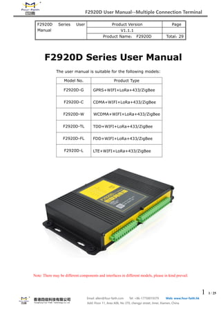
  • 1. F2920D User Manual--Multiple Connection Terminal 1 1 / 25 Email: allen@four-faith.com Tel: +86-17750019379 Web: www.four-faith.hk Add: Floor 11, Area A06, No 370, chengyi street, Jimei, Xiamen, China F2920D Series User Manual Product Version Page V1.1.1 Product Name: F2920D Total:29 F2920D Series User Manual The user manual is suitable for the following models: Note: There may be different components and interfaces in different models, please in kind prevail. Model No. Product Type F2920D-G GPRS+WIFI+LoRa+433/ZigBee F2920D-C CDMA+WIFI+LoRa+433/ZigBee F2920D-W WCDMA+WIFI+LoRa+433/ZigBee F2920D-TL TDD+WIFI+LoRa+433/ZigBee F2920D-FL FDD+WIFI+LoRa+433/ZigBee F2920D-L LTE+WIFI+LoRa+433/ZigBee
  • 2. F2920D User Manual--Multiple Connection Terminal 2 2 / 25 Email: allen@four-faith.com Tel: +86-17750019379 Web: www.four-faith.hk Add: Floor 11, Area A06, No 370, chengyi street, Jimei, Xiamen, China Files Revised Record Copyright Notice All contents in the files are protected by copyright law, and all copyrights are reserved by Xiamen Four-Faith Communication Technology Co., Ltd. Without written permission, all commercial use of the files from Four-Faith are forbidden, such as copy, distribute, reproduce the files, etc., but non-commercial purpose, downloaded or printed by individual (all files shall be not revised, and the copyright and other proprietorship notice shall be reserved) are welcome. Trademark Notice Four-Faith , 四信, , , are all registered trademarks of Xiamen Four-Faith Communication Technology Co., Ltd., illegal use of the name of Four-Faith trademarks and other marks of Four-Faith is forbidden, unless written permission is authorized in advance. Date Version Remark Author 2016-6-20 V1.0.0 Initial Version Zxz/Faine 2016-11-28 V1.1.0 Addition of parameter configuration instructions Hfq/qch 2016-12-22 V1.1.1 Addition of three-wire and four-wire power supply module description Jzq
  • 3. F2920D User Manual--Multiple Connection Terminal 3 3 / 25 Email: allen@four-faith.com Tel: +86-17750019379 Web: www.four-faith.hk Add: Floor 11, Area A06, No 370, chengyi street, Jimei, Xiamen, China Content Chapter 1 Brief Introduction of Product............................................................................................. 4 1.1 General............................................................................................................................................. 4 1.2 Features and Benefits................................................................................................................. 4 1.3 Working Principle.......................................................................................................................... 6 1.4 Specifications................................................................................................................................. 7 Chapter 2 Installation Introduction....................................................................................................12 2.1 General........................................................................................................................................... 12 2.2 Encasement List.......................................................................................................................... 12 2.3 Installation and Cable Connection....................................................................................... 12 2.4 Power...............................................................................................................................................15 2.5 Indicator Lights Instruction.................................................................................................... 16 2.6 Reset Button Introduction.......................................................................................................16 2.7 Three-Phase Four-Wire Power Supply Module (Optional)........................................17 Chapter 3 Configuration..........................................................................................................................18 3.1 Configuration Connection........................................................................................................ 18 3.2 Parameters Configuration Introduction..............................................................................18 3.3 Run the Configuration Software ..........................................................................................18 3.4 Configuration................................................................................................................................19 3.4.1 Central Station Parameters..........................................................................................19 3.4.2 Parameters of Monitored Area....................................................................................20 3.4.3 Basic Parameters............................................................................................................. 20 3.4.4 Ethernet Configuration.................................................................................................. 21 3.4.5 Wireless Network Configuration.................................................................................21 3.4.6 Camera Configuration....................................................................................................21 3.4.7 Terminal switch parameter configuration...............................................................22 Chapter 4 Data Transmission Environment Test........................................................................... 22 4.1 Network Structure of the Test Environment.................................................................... 22 4.2 Test Procedures........................................................................................................................... 23
  • 4. F2920D User Manual--Multiple Connection Terminal 4 4 / 25 Email: allen@four-faith.com Tel: +86-17750019379 Web: www.four-faith.hk Add: Floor 11, Area A06, No 370, chengyi street, Jimei, Xiamen, China Chapter 1 Brief Introduction of Product 1.1 General F2920D Terminal of Internet of things is a high-performance measuring and monitoring equipment, which integrates analog signal acquisition, switch input, relay output, RS485 communication, LoRa, WIFI, 433MHz, ZigBee, and cellular wireless communication. It can access different equipments and realize the monitoring and control function of the equipment through different communication modes. It has been widely used in the M2M fields, such as smart grid, intelligent transportation, smart home, finance, POS, supply chain automation, industrial automation, intelligent building, fire, public safety, environmental protection, weather, Digital medical, telemetry, military, space exploration, agriculture, forestry, water supply, coal, petrochemical, and so on. Typical applications are shown in Figure 1-1: 1.2 Features and Benefits Designed for industrial application ● Adopt high-powered industrial module ● Adopt high-powered industrial 32 bits CPU ● Embedded Real Time Clock(RTC) circuit which can realize timing online/offline function ● Housing: iron, providing IP30 protection. The iron housing safely isolates the terminal from the system, which is especially suitable for the industrial application. ● Power Range: DC 5~36V
  • 5. F2920D User Manual--Multiple Connection Terminal 5 5 / 25 Email: allen@four-faith.com Tel: +86-17750019379 Web: www.four-faith.hk Add: Floor 11, Area A06, No 370, chengyi street, Jimei, Xiamen, China Stability and Reliability ● WTD design ensures the stability of the system ● Auto recovery mechanism makes it always online ● RS232/RS485/RS422 port: 15KV ESD protection ● SIM/UIM port: 15KV ESD protection ● Power port: reverse-voltage and overvoltage protection ● Antenna port: lightening protection (optional) Standard and Convenience ● Adopt terminal block interface, convenient for industrial application ● Support standard RS232 and RS485 port that can connect to serial devices directly ● Support intellectual mode, enter into communication state when powered ● Provide management software for remote management (optional) ● User-friendly, flexible, and multiple operating modes ● Convenient configuration and maintenance interface ● Support serial software upgrading and remote maintenance High-Performance ● Support TCP server and TCP 4 clients connection (optional) ● Support 8 digital inputs, 2 analog inputs, 3 relay output channels and 1 10M/100M Ethernet interface ● Compatible 2G/3G/4G LTE full band and frequency ● Support WiFi hot spot ● Support LoRa, 433MHZ, and ZigBee ● Support domain name(DNS) and IP access to data center ● Design with standard TCP/IP protocol stack, and support transparent data transfer ● Support mass storage expansion ● Interactive management: remote management(optional), APP(optional), and local management via RS232 Standards ● Functional and Technical Standard of Rural Intelligent Power Distribution Terminal: Q/GDW615-2011. ● Communication Protocol of Electricity Data Acquisition and Management System: Q/GDW-11-143. ● Functional Specifications of Power Distribution Automation Terminal (Sub-Station): Q/GDW514. ● Implementing Rules of DL/T 634.5101-2001 Protocol. ● Performance of insulation, vibration, and anti-interference meet the standard of Q-GDW615-2011. ● Electrostatic Discharge: can withstand GB/T 17626.2-2006 of the IV level of electrostatic discharge interference test. ● Radiated susceptibility: can withstand the GB/T 17626.3 of the IV level RF electromagnetic field immunity. ● EFT/B immunity test:can withstand the GB/T 17626.12 of the IV class fast pulse group interference test. ● Surge immunity:can withstand the GB/T 17626.5 of the IV level surge (impact) interference test. ● Damped oscillatory magnetic field immunity: Can withstand the GB/T 17626.10 of the IV level damping oscillation magnetic field immunity test.
  • 6. F2920D User Manual--Multiple Connection Terminal 6 6 / 25 Email: allen@four-faith.com Tel: +86-17750019379 Web: www.four-faith.hk Add: Floor 11, Area A06, No 370, chengyi street, Jimei, Xiamen, China Applications ● Monitoring and Protection of Transformer: collect data of the smart meters and switchgears on the incoming lines. ● User Electricity Data Monitoring: collect meter data of users. ● Distribution Meter Monitoring: collect meter data and monitor its operating conditions. ● Monitoring of Residual Current Operated Circuit Breaker: residual current value monitoring, residual current state monitoring, and remote control switch breaking/closing. ● Status Monitoring: 8 input and output channels of switchgear and the accuracy of remote communication is 100%. ● Power Quality Management: monitoring of smart capacitors for reactive compensation, three-phase unbalanced management and power quality data monitoring. ● Load Management: power control, remote control, and voltage monitoring ● Security: burglar alarm; support camera capture(optional). 1.3 Working Principle The principle chart is shown in Figure 1-2. Figure 1-2
  • 7. F2920D User Manual--Multiple Connection Terminal 7 7 / 25 Email: allen@four-faith.com Tel: +86-17750019379 Web: www.four-faith.hk Add: Floor 11, Area A06, No 370, chengyi street, Jimei, Xiamen, China 1.4 Specifications Cellular Item Content F2920D-G Standard and band EGSM 900/GSM 1800MHz, GSM 850/900/1800/1900MHz(optional) Compliant to GSM phase 2/2+ GPRS class 10, class 12(optional) Bandwidth 85.6Kbps TX power GSM850/900:<33dBm GSM1800/1900:<30dBm RX sensitivity <-107dBm F2920D-C Standard and band CDMA2000 1xRTT 800MHz, 800/1900MHz(optional), 450MHZ(optional) Bandwidth 153.6Kbps TX power <30dBm RX sensitivity <-104dBm F2920D-W Standard and band UMTS/WCDMA/HSDPA/HSUPA/850/1900/2100MHz, 850/900/1900/2100MHz(optional) GSM 850/900/1800/1900MHz GPRS/EDGE CLASS 12 Bandwidth HSUPA: Upload speed 5.76Mbps HSDPA: Download speed 7.2Mbps, UMTS: 384Kbps (Download&Upload Speed) TX power <24dBm RX sensitivity <-109dBm F2920D-V Standard and band CDMA2000 1X EVDO Rev A 800MHz, 800/1900MHz(optional), 450MHz(optional) IS-95 A/B, CDMA2000 1X RTT Bandwidth Download speed 3.1Mbps, Upload speed 1.8Mbps TX power <23dBm RX sensitivity <-107dBm F2920D-TL Standard and band LTE TDD 2600/1900/2300MHz(Band38/39/40), Optional: 800/1400/1800MHz(Band 27/61/62)
  • 8. F2920D User Manual--Multiple Connection Terminal 8 8 / 25 Email: allen@four-faith.com Tel: +86-17750019379 Web: www.four-faith.hk Add: Floor 11, Area A06, No 370, chengyi street, Jimei, Xiamen, China TD-SCDMA 2010/1900MHz(A/F frequency band, Band 34/39) GSM /GPRS/EDGE 900/1800/1900MHz Bandwidth LTE TDD: Download speed 61Mbps, Upload speed 18Mbps TD-HSPA+: Download speed 4.2Mbps, Upload speed 2.2Mbps TD-HSPA: Download speed 2.8Mbps, Upload speed 2.2Mbps TX power <23dBm RX sensitivity <-97dBm F2920D-FL Standard and band LTE FDD 2600/2100/1800/900/800MHz, 700/1700/2100MHz(optional) DC-HSPA+/HSPA+/HSDPA/HSUPA/UMTS/850/900/2100MHz, 800/850/1900/2100MHz(optional) EDGE/GPRS/GSM 850/900/1800/1900MHz GPRS CLASS 10 GPRS CLASS 12 Bandwidth LTE FDD: Download speed 100Mbps, Upload speed 50Mbps DC-HSPA+: Download speed 42Mbps, Upload speed 5.76Mbps HSPA+: Download speed 21Mbps, Upload speed 5.76Mbps HSDPA: Download speed 7.2Mbps, HSUPA: Upload speed 5.76Mbps UMTS: 384Kbps TX power <23dBm RX sensitivity <-97dBm F2920D-L Standard and band LTE FDD,LTE TDD,EVDO,WCDMA,TD-SCDMA,CDMA1X,GPRS/EDGE Bandwidth LTE FDD: Download speed 100Mbps, Upload speed 50Mbps LTE TDD: Download speed 61Mbps, Upload speed 18Mbps DC-HSPA+: Download speed 42Mbps, Upload speed 5.76Mbps TD-HSPA+: Download speed 4.2Mbps, Upload speed 2.2Mbps EVDO Rev. A: Download speed 3.1Mbps, Upload speed 1.8Mbps TX power <23dBm RX sensitivity <-97dBm
  • 9. F2920D User Manual--Multiple Connection Terminal 9 9 / 25 Email: allen@four-faith.com Tel: +86-17750019379 Web: www.four-faith.hk Add: Floor 11, Area A06, No 370, chengyi street, Jimei, Xiamen, China LoRa 433MHZ ZigBee WIFI Item Content Standard and band IEEE 802.11 b/g/n, 2.4-2.5GHZ Bandwidth IEEE802.11 b/g: 54Mbps(Maximum) IEEE802.11n: 150Mbps(Maximum) Security WEP/WPA/WPA2 Item Content Standard and band 410MHz - 441MHz/1000KH; 433±5MHz(Suggestion); 433.0MHz(Default Value) Indoor/Urban Communication Distance 1000m Outdoor/Visual Communication Distance 3500m TX Power 20dBm Bandwidth -140Bm RX Sensitivity 6 levels selectable(0.3、0.6、1.0、1.8、3.1、5.5Kbps) Channel 32 Item Content Standard and band 387 - 464MHz; 430-436MHz(Suggestion); ±5MHz(Deviation) Outdoor/Visual Communication Distance 200m @1.2Kpbs TX Power 10dBm RX Sensitivity -110dBm@2.4Kpbs Modulation FSK/GFSK/ASK (MSK is not supported) Maximum Transfer Rate 500Kbps Item Content Standard and band IEEE 802.15.4, 2.4-2.5GHZ Indoor/Urban Communication Distance 90m Outdoor/Visual Communication Distance 2000m TX Power 20dBm RX Sensitivity -103dBm Bandwidth 250Kbps Number of Channel 11 to 26 Maximum Serial Memory 300 Bytes
  • 10. F2920D User Manual--Multiple Connection Terminal 10 10 / 25 Email: allen@four-faith.com Tel: +86-17750019379 Web: www.four-faith.hk Add: Floor 11, Area A06, No 370, chengyi street, Jimei, Xiamen, China TX Power <18dBm RX Sensitivity <-75dBm Hardware Interface Item Content Serial ● 1 RS232 port (Compatible RS485) and 1 RS485 port, 15KV ESD protection ● Data bits: 5, 6 ,7, 8 ● Stop bits: 1, 1.5, 2 ● Parity: none, even, odd, space, mark ● Baud Rate: 110~230400 bits/s Indicator “PWR”, “SYS”, “SIM”, “ALM”, “Online”, “ETH”, “WIFI”, “433/ZigBee”, “LoRa” and signal strength indicator Antenna ● Cellular: 1 Standard SMA female interface, 50 ohm lighting protection ● WIFI: 1 Standard SMA female interface, 50 ohm lighting protection (optional) ● 433/ZigBee: 1 Standard SMA female interface, 50 ohm lighting protection (optional) ● LoRa: 1 Standard SMA female interface, 50 ohm lighting protection (optional) SIM/UIM Standard 3V/1.8V user card interface, 15KV ESD protection Application 8 input and output channels (optical isolation); Definition: 2ms Logic 0: Wet node 0-3VDC, or dry note conducting Logic 1: Wet node 5-30VDC, or dry note conducting 3 relay output interfaces Maximum switching voltage: 250VAC/30VDC Maximum switching current: 5A 2 analog signal input interfaces 4 ~ 20mA current signal input, 0~5V voltage signal input (optional), accuracy: 0.5% 1 controlled output power supply The output voltage is the same as the device supply voltage, default value is 12V Output Current:1A; ESD protection Power Terminal block interface, reverse-voltage and overvoltage protection Item Content CPU Industrial 32 bits CPU FLASH 512KB SRAM 256KB
  • 11. F2920D User Manual--Multiple Connection Terminal 11 11 / 25 Email: allen@four-faith.com Tel: +86-17750019379 Web: www.four-faith.hk Add: Floor 11, Area A06, No 370, chengyi street, Jimei, Xiamen, China Note: There may be different components and interfaces in different models, please in kind prevail. Power Input Power Consumption Physical Characteristics Item Content Housing Iron, providing IP30 protection. The iron housing safely isolates the terminal from the system, which is especially suitable for the industrial application. Dimensions 91x58.5x22 mm (Antenna and mounting parts are not included) Weight About 800g Environmental Limits Item Content Operating Temperature -40 ~ +75°C (-40~ +167°F) Storage Temperature -40 ~ +85°C (-40 ~ +185°F) Ambient Relative Humidity 95% (non-condensing) Item Content Standard Power DC 12V/1.5A Power Range DC 5~36V Item Content Average consumption 250mA@12VDC Maximum dynamic consumption 700mA@12VDC
  • 12. F2920D User Manual--Multiple Connection Terminal 12 12 / 25 Email: allen@four-faith.com Tel: +86-17750019379 Web: www.four-faith.hk Add: Floor 11, Area A06, No 370, chengyi street, Jimei, Xiamen, China Chapter 2 Installation Introduction 2.1 General The device must be correctly installed to achieve the designed function. Generally, the device must be installed under the guidance of qualified engineers that approved by our company. Warning: Forbid to install when powered! 2.2 Encasement List Please keep the packaging material for later use when you unpack it. The list is as follows:  1 F2920D Terminal (Packing depends on user order)  1 user manual CD  1 card antenna (SMA anode) optional  1 WIFI antenna (SMA cathode) optional  1 LoRa antenna (SMA anode) optional  1 433 antenna (SMA cathode) optional  1 ZigBee antenna (SMA anode) optional  1 Transformer (optional)  1 RS232 cross wire (or 1 RS485 wire, optional)  One 1 1 PIN terminal joint 2.3 Installation and Cable Connection Shape and dimensions: On both sides of the device, there are fixed holes.In order to be user-friendly, following is the specific size of the device. (Unit: mm)
  • 13. F2920D User Manual--Multiple Connection Terminal 13 13 / 25 Email: allen@four-faith.com Tel: +86-17750019379 Web: www.four-faith.hk Add: Floor 11, Area A06, No 370, chengyi street, Jimei, Xiamen, China Antenna and SIM Card Installation: The SMA anode of WAN antenna should be screwed to the SMA cathode socket (marked as “ANT”) tightly to make sure it doesn’t affect the signal quality. The SMA cathode of WIFI antenna should be screwed to the SMA anode socket (marked as “WIFI”) tightly to make sure it doesn’t affect the signal quality. The SMA cathode of LoRa antenna should be screwed to the SMA anode socket (marked as “LoRa”) tightly to make sure it doesn’t affect the signal quality. The SMA cathode of 433/ZigBee antenna should be screwed to the SMA anode socket (marked as “433/ZigBee”) tightly to make sure it doesn’t affect the signal quality. When installing or removing SIM / UIM card,remove the bezel with a screwdriver first, then insert the tip of sharp object into the small dot on the right side of the SIM / UIM card holder, and the SIM / UIM card holder will eject. To install the SIM / UIM card, firstly insert the SIM / UIM card into the card holder and make sure
  • 14. F2920D User Manual--Multiple Connection Terminal 14 14 / 25 Email: allen@four-faith.com Tel: +86-17750019379 Web: www.four-faith.hk Add: Floor 11, Area A06, No 370, chengyi street, Jimei, Xiamen, China the metal surface facing out, then insert the SIM / UIM card holder, ensure it is inserted in place, and finally installed the baffle. Interface signal definition Description (terminal spacing 5.08mm): JP1 JP2 PIN Interface Name Explanation PIN Interface Name Explanation 1 PWR+ Power Input: DC 12V 1 DGND Data Ground 2 PWR- 2 DI1 Data Input 1 3 GND Power Ground 3 DI2 Data Input 2 4 RXD Receive Data 4 DI3 Data Input 3 5 TXD Transmit Data 5 DI4 Data Input 4 6 A1 RS485-1 A Port 6 DI5 Data Input 5 7 B1 RS485-1 B Port 7 DI6 Data Input 6 8 A2 RS485-2 A Port 8 DI7 Data Input 7 9 B2 RS485-2 B Port 9 DI8 Data Input 8 10 12V+ Output: 12V/1A, Power Supply to Camera 10 A1 Analog Input 1 11 12V- 11 A2 Analog Input 2 Note: RXD and TXD can not be used with RS485-1 at the same time. 12 AGND Analog Ground 13 K1+ Relay Output 114 K1- 15 K2+ Relay Output 216 K2- 17 K3+ Relay Output 318 K3- Cable Installation: Adopt industrial terminal interface, the recommended power wire and data cable should be 28-16AWG. Power and data interface cable connection diagram: 1 2 3 PWR- PWR+ GND + Anode - Cathode 1 2PWR- PWR + Anode - Cathode Connect via RS232 Connect via RS485
  • 15. F2920D User Manual--Multiple Connection Terminal 15 15 / 25 Email: allen@four-faith.com Tel: +86-17750019379 Web: www.four-faith.hk Add: Floor 11, Area A06, No 370, chengyi street, Jimei, Xiamen, China Switch Input Wiring: Relay Output Wiring: 2.4 Power Devices are often used in complex external environments. In order to adapt to the complex application environment and improve the stability of the system, the device uses advanced power technology. Users can use the configuration of 12VDC / 1.5A power adapter to power the device, or use DC 5 ~ 36V as power supply directly. When uses the external power supply to power the device, user must ensure the stability of the power supply (ripple < 300mV, instantaneous voltage ≦36V), and the power is more than 18W. It is recommended to use the standard 12VDC / 1.5A power supply. Note: When use the equipment as the power supply of camera, the input voltage must be 12V, and select the appropriate power supply according to the power consumption of selected camera.
  • 16. F2920D User Manual--Multiple Connection Terminal 16 16 / 25 Email: allen@four-faith.com Tel: +86-17750019379 Web: www.four-faith.hk Add: Floor 11, Area A06, No 370, chengyi street, Jimei, Xiamen, China 2.5 Indicator Lights Instruction The device provides “PWR”, “SYS”, “SIM”, “ALM”, “Online”, “ETH”, “WIFI”, “433/ZigBee”, “LoRa”, and signal strength indicator. The state of each indicator light is as follows: 2.6 Reset Button Introduction The device has a reset button labeled "RST". The function of the button is to resume to the default value settings.Method is as follows: Insert the "RST" hole with a sharp object and gently press and hold the reset button for about 10 seconds, then the device will automatically restore the parameter configuration to the factory value.After about 10 seconds , the device will automatically Indicator Light State Introduction PWR ON F2920D Terminal is powered on OFF F2920D Terminal is powered off SYS BLINK The system is running normally OFF There’s something wrong with the system SIM ON The device recognizes the SIM card OFF No SIM card was identified ALM ON Abnormal Situation Occurs OFF Everything is normal Online ON The device has logged on network and the platform BLINK The device has logged on network but not the platform OFF The device hasn’t logged on the network ETH ON Ethernet interface has connected OFF Ethernet interface hasn’t connected WIFI ON Connected via WIFI OFF Doesn’t Connect via WIFI 433/ZigBee ON Connected via 433/ZigBee OFF Doesn’t Connect via 433/ZigBee LoRa ON Connected via LoRa OFF Doesn’t Connect via LoRa Signal Strength ONE LIHGHT ON Weak Signal Strength TWO LIGHTS ON Good Signal Strength THREE LIGHTS ON Excellent Signal Strength
  • 17. F2920D User Manual--Multiple Connection Terminal 17 17 / 25 Email: allen@four-faith.com Tel: +86-17750019379 Web: www.four-faith.hk Add: Floor 11, Area A06, No 370, chengyi street, Jimei, Xiamen, China restart (auto restart is as follows: "SYS" indicator light will be off for about 10 seconds, and then work normally). 2.7 Three-Phase Four-Wire Power Supply Module (Optional) In order to use in specific occasions and make sure that there is no missing phrase operation, users can choose this three-wire&four-wire input power module. The output voltage is 12V/2A. Reserve one 13.5V 0.3-0.6A power supply so as to charge the backup battery. The dimensions and pins are defined as follows: Pin Function Definition  K1: Power failure of AC three-phase is the low battery alarm signal (The normal high-level input voltage is 12V)  K2: Terminal of power on alarm in the AC three-phase system (The normal high-level input 1 La Adopt Three-Phrase Four-Wire System, AC input via A-Phrase 7 B- Cathode 2 Lb Adopt Three-Phrase Four-Wire System, AC input via B-Phrase 8 B+ Anode 3 Lc Adopt Three-Phrase Four-Wire System, AC input via C-Phrase 9 K1 Rechargeable battery output signal when charging 4 N Adopt Three-Phrase Four-Wire System, AC input via N line 10 K2 Three-phrase four-wire system output signal online 5 -V1 12V Output Cathode 11 GND Power Ground 6 +V1 12V Output Anode
  • 18. F2920D User Manual--Multiple Connection Terminal 18 18 / 25 Email: allen@four-faith.com Tel: +86-17750019379 Web: www.four-faith.hk Add: Floor 11, Area A06, No 370, chengyi street, Jimei, Xiamen, China voltage is 12V)  Rated Power: 30W; Ripple and Noise:120mV  Support over-voltage protection (AC360-420V)  Battery Low Voltage Protection: the battery voltage switch will be of when the voltage between 10V-10.5V. Chapter 3 Configuration 3.1 Configuration Connection Before configuring the F2920D, connect the F2920D to the configured PC through RS232 cable or RS232-485 conversion cable, as shown in the following figure: 3.2 Parameters Configuration Introduction One way for F2920D parameter configuration: ● Configuration software: all the configurations are done through the configuration software.The configuration method is convenient for users to set the parameters through PC. Following is the specific introduction of F2920D configuration via configuration software. 3.3 Run the Configuration Software F2920D_Set.exe
  • 19. F2920D User Manual--Multiple Connection Terminal 19 19 / 25 Email: allen@four-faith.com Tel: +86-17750019379 Web: www.four-faith.hk Add: Floor 11, Area A06, No 370, chengyi street, Jimei, Xiamen, China The “Serial”area shows the current serial port setting.The default value is COM1,115200. To configure F2920D, please choose correct value to open the serial port.If the button text is “Close”, that means the serial port has been opened. If the text is “Open”, you should open the port first. When the port opened, the “Output Info”column will display “Port(COM1) Has Opened”. 3.4 Configuration Before using the configuration tool, please click the “Query” button first, the version of all the data will be read into the tool, it’s easy to view and revise. 3.4.1 Central Station Parameters  IP Address and Port of Main Server  The IP address and port of main server should be set at 1024 or above.  IP Address and Port of Backup Server  The IP address of server in the backup center.  Wireless Network Parameters APN: Password of wireless network access point. Mobile Number Set in the Main Server: Mobile number that the main station will call via wireless network when Abnormal Situation Occurs. Number set for Receiving Message from SMS Center: Mobile number that the main station will
  • 20. F2920D User Manual--Multiple Connection Terminal 20 20 / 25 Email: allen@four-faith.com Tel: +86-17750019379 Web: www.four-faith.hk Add: Floor 11, Area A06, No 370, chengyi street, Jimei, Xiamen, China send message to via wireless network. Virtual Private Network Username: User name for wireless network authentication. Virtual Private Network Password: Wireless network authentication password. 3.4.2 Parameters of Monitored Area According to different customers’ requirements, user can set the voltage,current and temperature threshold. The specific items can be set as follows: 3.4.3 Basic Parameters ● Replay Interval PPP Reconnection Interval; Replay Interval; Unit: 10S ● Terminal address Be used to identified the terminal address in background, because different terminals has been set different addresses. ● Main serial port mode Pure Data Transparent: data from serial port has been transparently passed. Serial Port Expansion: need to judge the protocol and forward it. Standalone Device: standalone device is used for data collection ● Data Acquisition Interval
  • 21. F2920D User Manual--Multiple Connection Terminal 21 21 / 25 Email: allen@four-faith.com Tel: +86-17750019379 Web: www.four-faith.hk Add: Floor 11, Area A06, No 370, chengyi street, Jimei, Xiamen, China The unit of data acquisition time interval is second. ● Time Interval of Switch State Querying The unit of time interval for switch state querying is second. ● Number of Configured Switches The number of switches that can be used and the number of switches that has been set will show in the interface of terminal switch configuration parameters. ● Switch Hardware Interface The optional interfaces of terminal hardware are 485-1 and 485-2. 3.4.4 Ethernet Configuration ● Ethernet Parameters Set the terminal’s Ethernet IP and gateway address and so on. Communication with the platform or communication with the camera can be realized through Ethernet. 3.4.5 Wireless Network Configuration Set the user name and password for connecting to the network according to the current configuration of wireless network. 3.4.6 Camera Configuration Types of Camera
  • 22. F2920D User Manual--Multiple Connection Terminal 22 22 / 25 Email: allen@four-faith.com Tel: +86-17750019379 Web: www.four-faith.hk Add: Floor 11, Area A06, No 370, chengyi street, Jimei, Xiamen, China Select the type of camera you are using from the drop-down menu, the optional types are SXH, HASX and IPCHK. Camera Hardware Interface When selecting the camera to access the terminal hardware interface, users need to note that different cameras use different hardware interfaces. For example,IPCHK uses Ethernet interface. ID Camera ID Set the camera ID as communication identification for the terminal and the camera. Camera Resolution Used to initialize the camera and set the resolution of collected images. 3.4.7 Terminal switch parameter configuration Please see the“Number of Configured Switches” in 3.4.3 Basic Parameters to set the number of terminal switches. Chapter 4 Data Transmission Environment Test 4.1 Network Structure of the Test Environment
  • 23. F2920D User Manual--Multiple Connection Terminal 23 23 / 25 Email: allen@four-faith.com Tel: +86-17750019379 Web: www.four-faith.hk Add: Floor 11, Area A06, No 370, chengyi street, Jimei, Xiamen, China Cloud Platform: Simulating the actual application of the data center to log on the page,and select the corresponding terminal address, user can query the data that sent by terminal. Assuming that the cloud platform IP address is 121.40.136.108, and the monitoring via port 19011. APP: Open the APP, select the corresponding terminal (distinguish through the terminal address), then the data collected by the terminal and the configuration information will show on the APP in real-time. Data acquisition: According to the set collection interval on PC, F2920D terminal will collect the value of the sensor through related media and protocols. (Media includes Ethernet, RS232, RS485, LoRa, 433, IO port, etc.). Following are the procedures of data transmission from collection terminal to server: Data Sensor→ F2920D analyses the received data, and encapsulate the information according to the 101 protocol → F2920D TCP / IP protocol stack encapsulate the data → sent to the wireless network → wireless network forwarding the data to the INTERNET →INTERNET forwarding the data to the Server. The procedures for server to send data to the PC are as follows: Server sends data to INTERNET-> INTERNET forwards data to wireless network -> F2920D 101 data for data analysis -> F2920D will be analyzed out of the data related settings. 4.2 Test Procedures 1. Run the F2920D_Set software on the PC, fill in the corresponding IP and port in the server parameters interface,then click “Set”when it’s done (If needed,it can be configured as different port). Please operate as the 1,2,3 steps show in the picture, and click the “Query” button before filling in IP and port information.
  • 24. F2920D User Manual--Multiple Connection Terminal 24 24 / 25 Email: allen@four-faith.com Tel: +86-17750019379 Web: www.four-faith.hk Add: Floor 11, Area A06, No 370, chengyi street, Jimei, Xiamen, China 2. Connect the sensor and F2920D terminal, and power on. If user need to read the terminal data, connect RS232 to the PC, then open the serial port. 3. Open the phone APP or web page (http://121.40.136.108:8056/index.do), select the
  • 25. F2920D User Manual--Multiple Connection Terminal 25 25 / 25 Email: allen@four-faith.com Tel: +86-17750019379 Web: www.four-faith.hk Add: Floor 11, Area A06, No 370, chengyi street, Jimei, Xiamen, China corresponding terminal,remember different terminals has different addresses. Terminal address setting please refer to the "Terminal address" in 3.4.3 Basic Parameters. The collected data can be viewed via APP or web pages, and the terminal device can be operated. APP interface is as follows: