
Recommended
More Related Content
Similar to Rapid-Prototyping.pdf
Similar to Rapid-Prototyping.pdf (20)
Recently uploaded
Recently uploaded (20)
Rapid-Prototyping.pdf
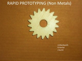
- 1. »Rapid Prototyping (Non metals) Aldi Manikanth me10b004 Harilal Ramesh me10b029 Sumit Jadhav me10b017 RAPID PROTOTYPING (Non Metals) A.Manikanth R.Harilal J.Sumit
- 2. Introduction Principle and definition Popular RP processes Applications Important issues in RP Conclusions
- 3. Why Rapid prototyping?...... » Human involvement in manufacturing processes is the bottleneck to speed. Therefore, eliminate or at least minimize it through automation. To increase effective communication. To decrease development time. To decrease costly mistakes. To minimize sustaining engineering changes. To extend product lifetime by adding necessary features and eliminating redundant features early in the design.
- 4. Definition » Rapid prototyping can be defined as a group of techniques used to quickly fabricate a scale model of a part or assembly using three-dimensional computer aided design (CAD) data. » It is more appropriate to call it as Layered Manufacturing » Compare with printing Pixels ≡ Voxels Raster ≡ Slices
- 5. The basic methodology for all current rapid prototyping techniques can be summarized as follows: 1. A CAD model is constructed, then converted to STL/VRML format. 2. The RP machine processes the .STL file by creating sliced layers of the model. 3. The first layer of the physical model is created. The model is then lowered by the thickness of the next layer, and the process is repeated until completion of the model. 4. The model and any supports are removed. The surface of the model is then finished and cleaned METHODOLOGY OF RAPID PROTOTYPING
- 6. Geometric input • It is possible to use any solid model or water-tight surface model. • Tessellated model is preferred due to its simplicity. • Triangular tessellation is preferred due to its robustness. • Most popular format is Standard Tesselation Language (STL) format. This was developed by 3D Systems. • STL file is an unordered collection of triangular faces (outward unit normal and 3 vertices – the order of these vertices follow RH Thumb rule w.r.t. the normal).
- 8. year Surface finish Layer thickness limits Place materials SLA 1986 0.1 mm Requires post- curing since 3D Systems of Valencia, California , USA, light- sensitive liquid polyme SLS 1989. DTM™ of Austin, Texas, USA nylon, elastome r, and soon metal; LOM Helisys of Torrance, California , USA Paper, plastics SGC Cibital , Israel FDM 1988. thermopl astics, such as ABS
- 10. Stereo lithography Process The sequence of steps for producing an Stereo lithography (SLA) layer is shown in the following figures:
- 12. 1. Layer adhesion. 2. Tracing the outline using LASER. 3. Cross hatching. 4. Lowering the platform and rolling in fresh sheet. 5. Repositioning. 6. The process can now be repeated. Material is usually a paper sheet laminated with adhesive on one side, but plastic and metal laminates are upcoming.
- 14. Solid Ground Curing • Photopolymer is used (Liquid) • Optical masking • As the entire area is exposed together, this process is very fast. Similar to LOM, build time is proportional to the surface area and not volume. • Explicit support structures are required. This is achieved simply by pouring wax in the regions not affected by the light; no need for computing the region requiring support and modify the CAD model. • The power of the laser and exposure time decides the layer thickness.
- 16. Highlights of Selective Laser Sintering • Laser beam selectively fuses powder materials: nylon, elastomer, and soon metal. • Advantage over SLA: Variety of materials and ability to approximate common engineering plastic materials. • Process is simple: There are no masking steps required. • Living hinges are possible with the thermoplastic-like materials. • Powdery, porous surface unless sealant is used. Sealant also strengthens part. • Uncured material is easily removed after a build by brushing or blowing it off.
- 19. FUSED DEPOSITION MODELLING Fused deposition modelling (FDM) is an additive manufacturing technology used for modelling, prototyping, and production applications. A plastic filament or metal wire is unwound from a coil and supplies material to an extrusion nozzle which can turn the flow on and off. The nozzle is heated to melt the material and can be moved in both horizontal and vertical directions by a Numerically Controlled mechanism, directly controlled by a computer-aided manufacturing (CAM) software package. Stepper motors or servo motors are typically employed to move the extrusion head. The thermoplastic material which we use here is ABS(Acrylonitrile butadiene styrene).
- 20. PERFACTORY Perfactory is the short form of “Personal factory” The Perfactory system builds 3D objects from liquid resin, like stereo lithography, but using a projector rather than a laser. It builds solid 3D objects by using the DLP projector to project sequential voxel planes into liquid resin, which then causes the resin to cure from liquid to solid. Each voxel plane made up of tiny Voxels (volume pixels), with dimensions as small as 16 μm x 16 μm x 15 μm in X, Y and Z direction. Dynamic Voxel Thickness gives you control over z build thicknesses from 15 μm to 150 μm
- 22. Supports
- 23. Support structures Process Support LOM Remaining sheet stock FDM Coarse deposition of a different material with poor adhesion. SLA Buoyancy of the liquid photo- polymer. Additionally, part geometry is modified to have weak supporting elements. SGC Wax SLS Remaining uncured powder
- 24. APPLICATIONS In Medicine It was recognized quite early that rapid prototyping could bring great improvements to the fields of prosthetics and implantation. Previously, hip replacements and other similar surgeries were carried out using standard sized replacement parts selected from a range provided by manufacturers based on anthropomorphic data.
- 25. APPLICATIONS Jewellery and the related arts have been particularly affected. Fine Arts -Michelangelo created his sculpture David 19 feet tall with the help of rapid prototyping. Architectural modelling -for example, those of the, American architect Frank Gehry, are more faithfully and easily represented than they could be using traditional model construction methods.
- 26. LIMITATIONS • Staircase effect 1. Low accuracy . 2. Poor surface finish . • Limited sizes Not a serious issue. • Support structure: 1. Need for a support mechanism. 2. Support removal is time consuming. • Limited material options Only photopolymers and thermoplastics.
- 27. Conclusions Limitations of Virtual world model. Properties like noise, handling or styling in automotive industry. Hence necessity of techniques such as rapid prototyping essential.