SlideShare a Scribd company logo
1 of 45
Download to read offline
TECHNICAL MANUAL
STANDARD ATMOSPHERIC
MANUAL # 11513240
Rev E
i
TABLE OF CONTENTS
1 SAFETY_______________________________________________________________1
1.1 GENERAL______________________________________________________________ 1
1.2 OXYGEN DEFICIENT ATMOSPHERES ___________________________________ 1
1.3 OXYGEN ENRICHED ATMOSPHERES____________________________________ 2
1.4 NITROGEN AND ARGON ________________________________________________ 3
2 VESSEL INFORMATION ________________________________________________5
2.1 RECEIVING CHECKPOINTS_____________________________________________ 5
2.2 VACUUM CHECK PROCEDURE__________________________________________ 5
2.3 PHYSICAL DESCRIPTION _______________________________________________ 6
2.4 OPERATING DESCRIPTION _____________________________________________ 7
2.5 PRESSURE BUILD-UP SYSTEM __________________________________________ 7
2.6 ECONOMIZER SYSTEM_________________________________________________ 8
2.7 OPERATOR QUALIFICATIONS __________________________________________ 8
3 CONTROLS____________________________________________________________9
4 FILLING PROCEDURES _______________________________________________10
4.1 INITIAL FILL _________________________________________________________ 10
5 WITHDRAWAL PROCEDURES__________________________________________15
5.1 LIQUID DELIVERY ____________________________________________________ 15
5.2 GAS DELIVERY _______________________________________________________ 16
5.3 REGULATOR ADJUSTMENTS __________________________________________ 16
6 VESSEL HANDLING INSTRUCTIONS____________________________________18
6.1 VESSEL TIE DOWN GUIDELINES________________________________________ 20
7 GENERAL ____________________________________________________________22
ii
7.1 MAINTENANCE _______________________________________________________ 22
7.1.1 COMPATIBILITY AND CLEANING _____________________________________ 22
7.1.2 PERIODIC INSPECTION_______________________________________________ 22
7.1.3 SOLDERING__________________________________________________________ 22
7.1.4 VACUUM INTEGRITY_________________________________________________ 23
7.2 TROUBLESHOOTING __________________________________________________ 23
7.3 REPAIR _______________________________________________________________ 23
7.4 VALVE REPAIR _______________________________________________________ 24
7.5 REGULATOR REPAIR__________________________________________________ 26
7.6 GAUGE REPAIRS ______________________________________________________ 27
7.7 INNER TANK BURST DISC REPAIR _____________________________________ 27
7.8 TESTING AFTER REPAIR ______________________________________________ 29
7.9 REGULATOR MAINTENANCE INSTRUCTIONS __________________________ 30
7.10. NEW YORK CITY FIRE DEPARTMENT APPROVALS ____________________ 32
8 DRAWINGS ___________________________________________________________33
Revision Log Description
Rev A (10/15/01) Add 525 thru 1500 to this manual.
Rev B (08/21/02) Updated O&D C-11534201-A
Rev C (12/11/02) Update Section 7.9 and update O&Ds
Rev D (1/7/03) Add HS O&Ds to this manual
Rev E (8/27/03) Update HS O&Ds
1
1 SAFETY
1.1 GENERAL
Cryogenic containers, stationary or portable are from time to time subjected to assorted environmental
conditions of an unforeseen nature. This safety bulletin is intended to call attention to the fact that
whenever a cryogenic container is involved in any incident whereby the container or its safety devices are
damaged, good safety practices must be followed. The same holds true whenever the integrity or function
of a container is suspected of abnormal operation.
Good safety practices dictate the contents of a damaged or suspect container be carefully emptied as soon
as possible. Under no circumstances should a damaged container be left with product in it for an
extended period of time. Further, a damaged or suspect container should not be refilled unless the unit
has been repaired and re-certified.
Incidents which require that such practices be followed include: highway accidents, immersion of a
container in water, exposure to extreme heat or fire, and exposure to most adverse weather conditions
(earthquake, tornadoes, etc.) As a rule of thumb, whenever a container is suspected of abnormal
operation, or has sustained actual damage, good safety practices must be followed.
In the event of known or suspected container vacuum problems (even if an extraordinary circumstances
such as those noted above has not occurred), do not continue to use the unit. Continued use of a
cryogenic container that has a vacuum problem can lead to embrittlement and cracking. Further, the
carbon steel jacket could possibly rupture if the unit is exposed to inordinate stress conditions caused by
an internal liquid leak.
Prior to reusing a damaged container, the unit must be tested, evaluated, and repaired as necessary. It is
highly recommended that any damaged container be returned to Chart for repair and re-certification.
The remainder of this safety bulletin addresses those adverse environments that may be encountered
when a cryogenic container has been severely damaged. These are oxygen deficient atmospheres, oxygen
enriched atmospheres, and exposure to inert gases.
1.2 OXYGEN DEFICIENT ATMOSPHERES
The normal oxygen content of air is approximately 21%. Depletion of oxygen content in air, either by
combustion or by displacement with inert gas, is a potential hazard and users should exercise suitable
precautions.
Chapter
1
2
One aspect of this possible hazard is the response of humans when exposed to an atmosphere containing
only 8 to 12% oxygen. In this environment, unconsciousness can be immediate with virtually no warning.
When the oxygen content of air is reduced to about 15 to 16%, the flame of ordinary combustible
materials, including those commonly used as fuel for heat or light, may be extinguished. Somewhat below
this concentration, an individual breathing the air is mentally incapable of diagnosing the situation because
the onset of symptoms such as sleepiness, fatigue, lassitude, loss of coordination, errors in judgment and
confusion can be masked by a state of “euphoria,” leaving the victim with a false sense of security and
well being.
Human exposure to atmosphere containing 12% or less oxygen leads to rapid unconsciousness.
Unconsciousness can occur so rapidly that the user is rendered essentially helpless. this can occur if the
condition is reached by an immediate change of environment, or through the gradual depletion of oxygen.
Most individuals working in or around oxygen deficient atmospheres rely on the “buddy system” for
protection-obviously, the “buddy” is equally susceptible to asphyxiation if he or she enters the area to
assist the unconscious partner unless equipped with a portable air supply. Best protection is obtainable by
equipping all individuals with a portable supply of respirable air. Life lines are acceptable only if the area is
essentially free of obstructions and individuals can assist one another without constraint.
If an oxygen deficient atmosphere is suspected or known to exist:
1. Use the “buddy system.” Use more than one “buddy” if necessary to
move a fellow worker in an emergency.
2. Both the worker and “buddy” should be equipped with self-contained or
airline breathing equipment.
1.3 OXYGEN ENRICHED ATMOSPHERES
An oxygen-enriched atmosphere occurs whenever the normal oxygen content of air is allowed to rise
above 23%. While oxygen is nonflammable, ignition of combustible materials can occur more readily in
an oxygen-rich atmosphere than in air; and combustion proceeds at a faster rate although no more heat is
released.
It is important to locate an oxygen system in a well ventilated location since oxygen-rich atmospheres may
collect temporarily in confined areas during the functioning of a safety relief device or leakage from the
system.
3
Oxygen system components, including but not limited to, containers, valves, valve seats, lubricants,
fittings, gaskets and interconnecting equipment including hoses, shall have adequate compatibility with
oxygen under the conditions of temperature and pressure to which the components may be exposed in
the containment and use of oxygen. Easily ignitable materials shall be avoided unless they are parts of
equipment or systems that are approved, listed, or proved suitable by tests or by past experience.
Compatibility involves both combustibility and ease of ignition. Materials that burn in air may burn
violently in pure oxygen at normal pressure, and explosively in pressurized oxygen. In addition, many
materials that do not burn in air may do so in pure oxygen, particularly when under pressure. Metals for
containers and piping must be carefully selected, depending on service conditions. The various steels are
acceptable for many applications, but some service conditions may call for other materials (usually copper
or its alloy) because of their greater resistance to ignition and lower rate of combustion.
Similarly, materials that can be ignited in air have lower ignition energies in oxygen. Many such materials
may be ignited by friction at a valve seat or stem packing, or by adiabatic compression produced when
oxygen at high pressure is rapidly introduced into a system initially at low pressure.
1.4 NITROGEN AND ARGON
Nitrogen and argon (inert gases) are simple asphyxiates. Neither gas will support or sustain life and can
produce immediate hazardous conditions through the displacement of oxygen. Under high pressure
these gases may produce narcosis even though an adequate oxygen supply sufficient for life is present.
Nitrogen and argon vapors in air dilute the concentration of oxygen necessary to support or sustain life.
Inhalation of high concentrations of these gases can cause anoxia, resulting in dizziness, nausea, vomiting,
or unconsciousness and possibly death. Individuals should be prohibited from entering areas where the
oxygen content is below 19% unless equipped with a self-contained breathing apparatus.
Unconsciousness and death may occur with virtually no warning if the oxygen concentration is below
approximately 8%. Contact with cold nitrogen or argon gas or liquid can cause cryogenic (extreme low
temperature) burns and freeze body tissue.
Persons suffering from lack of oxygen should be immediately moved to areas with normal atmospheres.
SELF-CONTAINED BREATHING APPARATUS MAY BE REQUIRED TO PREVENT
ASPHYXIATION OF RESCUE WORKERS. Assisted respiration and supplemental oxygen should be
given if the victim is not breathing. If cryogenic liquid or cold boil-off gas contacts worker’s skin or eyes,
the affected tissue should be flooded or soaked with tepid water (105-115ºF or 41-46ºC). DO NOT USE
HOT WATER. Cryogenic burns that result in blistering or deeper tissue freezing should be examined
promptly by a physician.
4
Additional information on nitrogen and argon and liquid cylinders is available in CGA Pamphlet p-9.
Write to the Compressed Gas Association, Inc., New York, NY 10110.
N O T E :
Extracted from Safety Bulletin SB-2 from Compressed Gas Association, Inc., New York,
dated March 1966 and from the "Nitrogen Material Safety Data Sheet’" published by Air
Products and Chemicals, Inc., Allentown, PA 18105, dated 1 June 1978.
5
2 VESSEL INFORMATION
Although vessels may vary in piping and plumbing details, some general comments on configuration and
operation can be made.
2.1 RECEIVING CHECKPOINTS
1. Check braces, skids, wooden chocks, and other shipping supports. Damage or deformation
would indicate the possibility of mishandling during shipment.
2. Examine welded or brazed joints on plumbing for cracks or deformation, especially near
valves and fittings.
3. Check points where pipes exit the tank for cracks or breaks.
4. Check relief valves and burst discs for dirt or damage.
5. Check pressure within vessel on PI-1. If pressure is zero, extra precautions against
contamination and impurities must be taken.
6. Examine the 5g impactograph. If it has sprung, damage may have occurred during shipment.
Notify your company’s tank specialist and/or CHART.
7. Check the container vacuum.
a) If warm vacuum for "NC" models is above 20 microns, consult factory.
2.2 VACUUM CHECK PROCEDURE
CAUTION: UNAUTHORIZED CHANGING OF THE VACUUM PROBE WILL
VOID VESSEL WARRANTY.
1. The standard CHART vacuum probe is a Teledyne-Hastings DV-6R probe. Select a
compatible instrument to read the output of the vacuum probe.
2. Remove the rubber cap on probe outlet to expose contact. Note .that probe housing need not
be opened to do this.
3. Plug the instrument to the probe and calibrate the instrument.
Chapter
2
6
4. Open the vacuum probe isolation valve. Wait for 5 minutes and take vacuum reading. Note
that valve handle protrudes through protective housing and can be turned without opening
the housing.
5. Close the isolation valve and take a second reading. Monitor the rate of rise in vacuum probe
with isolation valve closed. If the vacuum continues to rise at a constant rate, it is possible that
the probe assembly is leaking. Consult the factory.
6. Verify that the isolation valve is closed.
7. Replace the rubber probe cap.
Compare the vacuum reading obtained now to reading taken prior to shipping.
2.3 PHYSICAL DESCRIPTION
A Chart vessel is designed for long-term storage of cryogenic liquefied gases under pressure in the range
of 5 PSI (0.4 kg/cm2) to the MAWP (Maximum Allowable Working Pressure). Operation of the station
can be fully automatic with the unit’s regulator system set to maintain preset pressure and flow conditions
into a customer’s pipeline. While hardware may vary slightly from model to model, each unit essentially
performs the same functions.
The vessel is comprised of an alloy steel inner tank encased in an outer carbon steel vacuum shell. The
insulation system between the inner and outer containers consists of composite insulation and high
vacuum to ensure long holding time. The insulation system designed for long-term vacuum retention is
permanently sealed at the factory to ensure vacuum integrity. The units have a tank pressure relief device,
which is set at the factory. As a secondary pressure relief device, the container is further protected from
over-pressurization by a rupture disc. The bursting disc will rupture completely to relieve inner tank
pressure in the event the tank relief valve fails and pressure exceeds the rupture disc setting. The vacuum
space is protected from over-pressurization by use of a tank annulus rupture disc assembly. Pressure
relief devices used on Chart vessels designed for the U.S. specifications meet the requirements of CGA
Pamphlet S1.3, “Pressure Relief Device Standards, Part 1, for Stationary Vessels.”
The stations are leg mounted. Lifting lugs are secured to the bottom head and to the top head of the
container. The lifting lugs are provided to facilitate handling. Moving requires the use of a crane and
adherence to specific rigging instructions, which may vary from vessel to vessel. Some Chart vessels
cannot be lifted with one hook only.
Controls Used To Operate The System Are Mounted Under And On The Sides Of The
Customer Station. The Pressure Gauge And Liquid Level Gauge Are Located At Eye Level On
The Container For Ease Of Viewing.
7
Single Regulator System
Single regulator system has a single regulator, which doubles as an economizer regulator and a pressure
building regulator. The regulator in the economizer circuit automatically allows vapor space gas to be
introduced preferentially into the final line or gas use circuit when the customer station pressure exceeds
the regulator setting. The pressure building circuit is responsible for maintaining a minimum set pressure
in the vessel.
Dual Regulator System
Dual regulator system has two regulators, which has an economizer regulator and a pressure building
regulator. The regulator in the economizer circuit automatically allows vapor space gas to be introduced
preferentially into the final line or gas use circuit when the customer station pressure exceeds the regulator
setting. The pressure building circuit is responsible for maintaining a minimum set pressure in the vessel
The normal operating pressure range of a vessel is from 60 PSI to approximately 175 PSI. Operating
pressure can be increased or decreased as desired by adjusting the regulator, for vessels requiring a
different range the PB/Econo regulator spring may be changed.
2.4 OPERATING DESCRIPTION
Vessel operation is governed by the pressure build-up system and the economizer system. The pressure
build-up system and the economizer system may be combined into a single regulator system for more
effective low withdrawal operations.
2.5 PRESSURE BUILD-UP SYSTEM
The pressure build-up system consists of an ambient air vaporizer and pressure building regulator. When
tank pressure becomes lower than the set point of the pressure building regulator, the regulator will open.
As a result, liquid will be able to flow through the vapor trap in the annulus, through the isolation valve
and regulator to be expanded to vapor in the pressure building coil. The vapor accumulates in the inner
tank vapor space to increase pressure. This flow continues until inner tank pressure is equal to regulator
setting. When the pressures are equal, the regulator closes. This system thus automatically maintains
station pressure as required.
** NOTE: Upon tank installation. The nuts mounting the PB coil (PBC-1) to the respective
brackets must be loosened ½ - ¾ turns to allow for expansion & contraction.
8
2.6 ECONOMIZER SYSTEM
The economizer system allows the excess gas, which accumulates in the vapor space during periods of
low or no use to be consumed preferentially, in effect, it acts like an adjustable in-line relief valve, venting
the tank into the customer use line. When vessel pressure is high, above the set point of the regulator, it
opens. This allows gas, which flows more easily than the liquid, to flow out of the vapor space, through
the isolation valve, regulator, and finally back into the tank to connect to the gas use line. This preferential
flow continues until the regulator closes. The single regulator is designed to automatically set the
economizer circuit to regulate at 7 PSI (0.5 kg/cm2) higher than that of the pressure building circuit. On
dual regulator systems the preset economizer regulator is set at 20PSI (1.4kg/cm2).
2.7 OPERATOR QUALIFICATIONS
Chart Stations are designed for safe and simple operation. The operator is expected to be knowledgeable
of the nature of the gas (es) with which he is working, as well as all applicable safety requirements. This
manual contains several chapters dealing with Operating instructions, Handling Instructions, and
Maintenance Procedures. To fully understand these procedures, we recommend the operator first
become familiar with controls and indicators.
9
3 CONTROLS
Chart cryogenic container operating procedures specify that the operator shall be familiar with all
controls and indicators as well as safety considerations. The following controls and indicators should
be located and identified on the vessel prior to filling or putting the vessel into operation.
For a list of controls and indicators, See Process & Instrument Diagram in Section 8.
Chapter
3
10
4 FILLING PROCEDURES
This chapter provides the initial fill, gas use, liquid delivery, and refilling procedures for the vessel
described in this manual. Before performing any of the procedures contained in this chapter, become
familiar with the location and function of the controls and indicators.
4.1 INITIAL FILL
The initial fill is usually performed on a warm vessel, one that has not been in use for an extended
period. The warm container must be purged to ensure product purity.
When preparing the tank for filling or when changing service, the following items should be
considered:
1. The vessel should be inspected for possible damage or unsuitability for intended use. If
damage is detected (e.g. serious dents, loose fittings, etc.) remove the unit from service
and perform repairs as soon as possible.
2. The vessel may be filled by pumping or pressure transfer. If vessel pressure is at least 50
PSI (3.5 kg/cm2) less than the maximum allowable pressure of the supply unit, liquid may
be transferred by pressure transfer. If the normal working pressure of the station is equal
to or grater than the maximum allowable pressure of the supply unit, liquid must be
pumped into the tank.
3. To remove the moisture or foreign matter from the tank or tank lines, the vessel must be
purged. Use a small amount of new product for purging when changing service and a
small amount of the same product if the purge is to ensure purity or remove
contaminants.
4. When changing service, the approved CGA (or other keyed) fitting will have to be
installed for connection FC-1.
Chapter
4
11
Table 1 Vessel Purging Procedure
STEP
NUMBER
Purging Procedure
CAUTION
The maximum purge pressure should be equal to 50 percent of the maximum operating pressure of the tank or
30 PSI (2.1 kg/cm
2
), whichever is less. The maximum purge pressure should be determined before starting the
purge operation. To prevent drawing atmospheric contaminants back into the tank, a positive pressure of at least
5 PSI (0.4 kg/cm
2
) must always be maintained in the tank.
Attach the source of liquid purge to the fill connection (FC-1).
1 Close all valves except the pressure build-up valves (HCV-3, HCV-11) and liquid level gauge vapor phase and
liquid phase shutoff valves (HCV-8, HCV-10).
2
NOTE
The pressure building/economizer regulator or pressure building regulator in the dual regulator system (PCV-1) is
normally set to build pressure to 120 PSI. When this pressure is used as the purge pressure, DO NOT adjust the
regulator adjusting screw. When a solenoid valve is used to control the pressure building circuit, it must be
energized.
Open hose drain valve (HCV-7), and allow source to vent through hose. Vent until slight frosting appears on
hose. Close hose drain valve (HCV-7).
3 Open the bottom fill valve (HCV-1) enough to allow liquid to flow slowly into the tank through the bottom fill line.
The gradual flow enables the liquid to vaporize in the line and pressure buildup coil and slowly build up pressure
in the inner tank.
4 Shut off the liquid supply source when the pressure in the tank reaches the maximum purge pressure as
indicated on tank pressure gauge (PI-1).
5 Open the fill line drain valve (HCV-7) slowly to avoid splashing of the liquid. Drain all liquid from the tank. The
appearance of gas (vapor) at the drain indicates that all liquid has been drained.
6 Close drain valve (HCV-7) and bottom fill valve (HCV-1).
7 Open the liquid level gauge equalization valve (HCV-9) to prevent damage to the gauge before closing the liquid
level gauge vapor phase and liquid phase shut-off valves. When all liquid is drained, close the liquid level gauge
vapor phase and liquid phase shut-off valves (HCV-8, HCV-10).
8 Loosen the unions on either side of the liquid level gauge (LI-1). Both the upper and lower liquid level gauge
valves (HCV-8, HCV-10) should be opened wide and the gas streams visually checked for signs of moisture.
Provided no moisture is observed after blowing the lines for approximately two minutes, both valves should be
closed. If moisture is observed in the gas stream, the gas should be discharged until it is clear of all moisture.
12
STEP
NUMBER
Purging Procedure
9
NOTE
A careful check for moisture in the phase lines will ensure trouble free operation of the liquid level gauge. Due to
their small diameter, gauge lines are easily plugged by ice.
10 Open the vapor vent valve (HCV-12) and full trycock valve (HCV-4). The top fill valve (HCV-2) will have to be
vented by opening hose drain valve (HCV-7).
11 Repeat purge procedure 2 through 6 and 10 at least three times to ensure product purity.
12 Reconnect the liquid level gauge (LI-1), open the liquid level control valves (HCV-8, HCV-10), then close the by-
pass valve (HCV-9).
13 After purging the tank, but before filling, verify that the following valves are open or closed as indicated.
Valve
Bottom fill valve HCV-1
Top fill valve HCV-2
Vapor vent valve HCV-12
Full trycock valve HCV-4
Liquid level gauge equalizing valve HCV-9
Product supply valve HCV-13
Pressure building inlet/outlet valves HCV-3/HCV-11
Economizer isolation valve HCV-17
Liquid level gauge liquid phase valve HCV-10
Liquid level gauge vapor phase valve HCV-8
Position
Closed
Closed
Closed
Closed
Closed
Closed
Closed
Closed
Open
Open
13
Table 2 Initial (Warm Tank) Filling Procedure
STEP
NUMBER
Initial (Warm Tank) Filling Procedure
1 Purge tank to assure product purity
2 Verify that the contents of the supply unit is the proper product to be transferred.
3 Verify that all valves except liquid phase-high (HCV-10) and gas phase-low (HCV-8) are closed.
4 Connect the supply unit transfer hose to tank fill connection (FC-1).
NOTE
Cool down the transfer hose prior to filling by opening hose drain valve (HCV-7) and venting the supply unit
through the hose for approximately three minutes. Close drain valve (HCV-7).
5 Open bottom fill valve (HCV-1) slowly. If a pressure transfer is to be made, allow pressure to build up in the
liquid supply unit until it is at least 50 PSI (3.5 kg/cm
2
) higher than station pressure. Open the discharge valve on
the supply unit to begin flow.
(or)
If a pump transfer is to be made, make the required connections to the pump. Open the supply unit transport
discharge valve slowly. Maintain pump discharge pressure from 50 PSI (3.5 kg/cm
2
) to 100 PSI (7.0 kg/cm
2
)
higher than the tank pressure. Fill slowly.
6 Monitor pressure in tank during filling. If pressure rises above supply pressure, or near relief valve pressure, the
tank may have to be vented through the vapor vent valve (HCV-12), should pressure continue to rise, the fill may
have to be interrupted to allow pressure to drop.
7 Monitor liquid level contents gauge (LI-1). When the gauge indicates approximately three-quarters full, open full
trycock valve (HCV-4)
8 When liquid spurts from full trycock valve (HCV-4), immediately stop fill at the supply source and close full
trycock valve (HCV-4).
9 Close bottom fill valve (HCV-1).
10 Drain residual liquid in the fill hose via drain valve (HCV-7).
11 Relieve fill hose pressure by loosening the hose at fill connection, then disconnect the hose. It is recommended
that the fill hose be allowed to defrost to prevent moisture from being drawn inside the hose.
14
Table 3 Vessel Refilling Procedure
STEP
NUMBER
Vessel Refilling Procedure
1
NOTE
Filling a cryogenic vessel through the bottom tends to raise pressure in the vessel as gases in vapor space are
compressed. Filling through the top tends to lower pressure as gases in head space are cooled down and re-
liquefied.
2 Verify that the contents of the supply unit is the proper product to be transferred.
3 Verify that the bottom and top fill valves are closed (HCV-1, HCV-2).
4 Verify minimum required operating pressure in vessel.
5 Verify that all other valves are in normal operating positions.
6 Connect the supply unit transfer hose to tank fill connection (FC-1).
7
NOTE
Cool and purge down the transfer hoses prior to filling by opening hose drain valve (HCV-7) and the supply unit
discharge valve for approximately three minutes or until hose begins to frost. Close drain valve (HCV-7).
8 Open top fill valve (HCV-2) completely.
If a PRESSURE TRANSFER is to be made, allow pressure to build up in the liquid supply unit until it is at least 50
PSI (3.5Kg/cm
2
) higher than station pressure. Open the discharge valve on the supply unit to begin flow.
(or)
If a PUMP TRANSFER is to be made, make the required connections to the pump. Open the supply unit transport
discharge valve slowly. Close pump circulating valve slowly, so as not to lose pump prime. Maintain pump
discharge pressure from 50 PSI (3.5 kg/cm
2
) to 100 PSI (7.0 kg/cm
2
) higher than tank pressure.
9 Monitor pressure in vessel as indicated. If pressure begins to drop to near the minimum operating pressure, begin
to open bottom fill valve (HCV-1), and throttle top fill valve (HCV-2), until pressure stabilizes.
10 Monitor liquid level contents gauge (LI-1). When the gauge indicates approximately three-quarters full, open full
trycock valve (HCV-4).
11 When liquid spurts from full trycock valve (HCV-4), stop fill at the supply source and close full trycock valve (HCV-
4).
12 Close tank fill valves (HCV-1, HCV-2).
13 Drain residual liquid in the fill hose via drain valve (HCV-7).
14 Relieve fill hose pressure by loosening the hose at the fill connection, and then disconnect the hose
15
5 WITHDRAWAL PROCEDURES
This chapter provides general guidelines for product decanting in either gaseous or liquid form for the
vessel described in this manual. Before performing any of the procedures contained in this chapter,
become familiar with the location and function of the controls and indicators.
N O T E
When using a vessel for gaseous service, a free standing vaporizer will have to be
installed between the Gas Use connection and a final line pressure regulating system.
5.1 LIQUID DELIVERY
Table 4 Liquid Withdrawal Procedure
STEP
NUMBER
Liquid Withdrawal Procedure
1 Connect customer line liquid withdrawal connection (C-1).
2 Verify that all valves except gauge liquid phase valve (HCV-10) and the gauge gas phase valve (HCV-8) are
closed.
3 Observe pressure building regulator/economizer regulator or pressure building regulator in the dual regulator
system (PCV-1) setting as indicated on the station pressure gauge (PI-1). If station pressure is too high, open
vent valve (HCV-12) to relieve excessive gas. It is possible that regulator springs will require changing for lower
operational pressure.
4 Open liquid withdrawal valve (HCV-18) slowly to begin liquid flow.
5 Once the desired amount of liquid has been delivered, close the liquid withdrawal valve (HCV-18).
Chapter
5
16
5.2 GAS DELIVERY
Table 5 Gas Withdrawal Procedure
STEP
NUMBER
Gas Withdrawal Procedure
1 Connect customer line to vessel gas use connection (VAP) or to the optional final line connection if used.
2 Verify that all valves except gauge liquid phase (HCV-10) and gauge gas phase (HCV-8) are closed.
3 Open product supply valve (HCV-13), pressure building inlet valve (HCV-3), PB outlet valve (HCV-11), and
economizer shut-off valve (HCV-17) to start gas flow. At this time, final line pressure gauge will be indicating
pressure in the customer line and the system will automatically deliver gas until stopped, or vessel is empty.
4 The liquid regulator will not open until the set pressure is reached, thus preferentially drawing vapor off the head
space.
Once the required amount of product has been delivered (or to close the tank down for an extended period of
time), stop gas flow by closing gas use valve (HCV-13). The operation of an Chart unit is completely automatic,
valves need to be opened and closed only during filling and during major maintenance.
5 Normal operating valve position for a VS unit are as follows:
Bottom fill valve HCV-1
Top fill valve HCV-2
Vapor vent valve HCV-12
Full trycock valve HCV-4
Liquid level gauge equalizing valve HCV-9
Hose drain valve HCV-7
Product supply valve HCV-13
Pressure building inlet/outlet valves HCV-3/HCV-11
Economizer isolation valve HCV-17
Liquid level gauge liquid phase valve HCV-10
Liquid level gauge vapor phase valve HCV-8
Closed
Closed
Closed
Closed
Closed
Closed
Open
Open
Open
Open
Open
5.3 REGULATOR ADJUSTMENTS
N O T E :
To field set or adjust regulators quickly the vessel must preferably be a full tank.
Under normal circumstances, the system does not require adjustment. However, it may be necessary
to change regulator settings to obtain either higher or lower pressure setting within the range of the
factory installed springs, at the time of starting up a vessel. It is good practice to verify set points
during an initial fill.
The adjustments which follows are required to “final set” the regulator following spring replacement,
or after completing valve repairs which required disassembly and reassembly.
17
Single Regulator System
The economizer regulator circuit will automatically be set 7 PSI (0.5 kg/cm2) higher than pressure
building regulator. The pressure building regulator should be set approximately 20 PSI to 40 PSI
higher than the desired delivery pressure. Detailed regulator adjustment procedures are provided in
tables.
Dual Regulator System
The economizer regulator is normally set 20 PSI (1.4 kg/cm2) higher than pressure building regulator.
The pressure building regulator should be set approximately 20 PSI (1.4 kg/cm2) to 40 (2.8 kg/cm2)
PSI higher than the desired delivery pressure. Detailed regulator adjustment procedures are provided
in tables.
Table 6 Pressure Building Regulator Adjustment
STEP
NUMBER
Pressure Building Regulator Adjustment
1 This procedure is best performed with a completely full tank, so that all changes in adjustment of the pressure
building regulator will be reflected rapidly. Observe reading on pressure gauge (PI-1). If pressure is lower
than desired set point of pressure building regulator/economizer regulator (PCV-1), proceed to Step 2; if
higher, proceed to step 3.
2 If tank pressure is below the desired setting, loosen the pressure screw lock nut on the regulator. With PB
Inlet and PB Outlet valves (HCV-3, HCV-11) open, gradually open regulator by turning the pressure screw
(clockwise) to build tank pressure to the desired setting. Note that the pressure screw should be adjusted in
small increments, allowing sufficient time for tank pressure to stabilize each time the screw is turned. The tank
can be considered stabilized when no frost is found on the pressure building circuit. This reduces the
possibility of over-shooting the desired pressure, which would in turn, require partial tank blow-down via the
vent valve (HCV-12). Tighten lock nut on regulator, and return vessel to normal service.
3 If the tank is above the desired setting, open vent valve (HCV-12) to vent excess gas. Should pressure
continue to rise above the desired level, proceed to step 4.
4 Again vent excess gas by opening vent valve (HCV-12). Reduce pressure until tank pressure gauge (PI-1)
indicates a reading of 10 PSI (0.7 kg/cm
2
) below the desired setting. Loosen set screw on PB
regulator/economizer valve (PCV-1), and proceed to Step 2, gradually decrease tank pressure by adjusting
the pressure screw (counter clockwise ).
18
6 VESSEL HANDLING INSTRUCTIONS
Figures 1 and 2 depict two methods of handling vessels during installation. The handling method
pictured in Figure 2 uses two cranes to place the tank. The two-crane method is the safer, and thus,
more preferred method of installing the vessel. The alternate method of installation uses a single
crane. This method is pictured in Figure 2.
Chapter
6
19
FIGURE 1, TWO-CRANE INSTALLATION METHOD
FIGURE 2, SINGLE-CRANE INSTALLATION METHOD
20
6.1 VESSEL TIE DOWN GUIDELINES
Chart Industries, Inc. Vessel Tie Down Guidelines 3/5/99
PURPOSE: TO BE GIVEN or SHOWN TO DRIVERS PRIOR TO LOADING IF POSSIBLE.
• Unless otherwise specified by customer, the tank should be orientated with the plumbed head pointing
backward. The plumbing is less likely to be damaged during shipping in this orientation.
• Place supports or saddles on the head-shell seam, never in the middle of the head.
• Using appropriately sized element, tie the vessel to the bed of the trailer at the lifting lugs on the top of the
vessel and at any lug clearly marked “Tie Down Only”.
• If no lugs exist on the bottom portion of a vertical tank, tie the vessel to the bed of the trailer at the mounting
holes on the leg pad. Attach elements to the vessel as close to the head as possible. If possible, avoid
attaching chains to the outer part of the leg.
• A minimum of eight elements should be used to secure any vessel. The elements should be situated such that
the tank cannot slide or roll in any direction.
• Straps can cause damage to the tank finish. Avoid using straps to secure the vessel.
• Under no circumstances should a chain, strap, or other tie down equipment that may damage the tank finish,
come in direct contact with the outer shell of the vessel. Use rubber pad, corrugated cardboard or a similar
material to protect the tank in areas where contact may occur. The trucker is responsible for providing these
materials when required.
• If additional blocking is required due to placing the vessel partially over the drop section of the trailer, the
trucker is responsible for providing that blocking.
Figure 1 below shows a side view of an acceptable element configuration for a conventional CHART vertical vessel.
Blocks or SaddlesChains
Chains
A
Figure 2 - Vertical Rear View Figure 1 - Vertical Side View Figure 3 - Vertical Frontal View
Figures 4 and 5 below show side and end views of a horizontal tank with tie down lugs on the saddle supports. The
element configuration shown is acceptable for this type of vessel. If a tank is not equipped with tie down lugs on
the saddle supports, use the holes in the saddle supports as tie down points. Use a chain configuration similar to
the figure below.
Figure 4 - Horizontal Side View Figure 5 - Horizontal End View
21
CABLE AND CHAIN TABLE
Tank Size
(gal)
Typ. Vessel Weight
(lbs)
Maximum Force in
Element (lbs)
Recommended Cable Recommended Chain
1500 10000 17800 (1) ½” IWRC 6X19 (2) ½” Transport Grade 7
3000 17000 30600 (1) ¾” IWRC 6X19 (3) ½” Transport Grade 7
6000 30000 53900 (1) ¾” IWRC 6X19 (2) 7/8” Alloy Grade 8
9000 45000 66200 (2) ¾” IWRC 6X19 (2) 7/8” Alloy Grade 8
11000 54000 79400 (2) ¾” IWRC 6X19 (3) 7/8” Alloy Grade 8
13000 63000 92700 (2) ¾” IWRC 6X19 (3) 7/8” Alloy Grade 8
15000 72000 106000 (2) ¾” IWRC 6X19 (3) 7/8” Alloy Grade 8
This table shows approximate Chart tank sizes and weights. Tank sizes and volumes are based
off of a standard 400 psi tank. Actual Tank weights may vary. Consult the data plate for the
actual tank weight. The maximum force in any element is found from the weakest element on
the vertical tank tie down configuration (Element "A"). If element "A" exceeds a 45 degree
angle from horizontal the force in the element will exceed the value indicated in the table.
** IT IS THE DRIVERS RESPONSIBILITY TO SECURE LOAD IN
ACCORDANCE WITH DOT REGULATIONS.
22
7 GENERAL
This chapter contains vessel maintenance information, including troubleshooting and repair
procedures. Before performing any of the procedures in this chapter, be sure you are familiar with
the location and function of controls and indicators discussed in other chapters.
7.1 MAINTENANCE
7.1.1 COMPATIBILITY AND CLEANING
It is essential to always keep the vessel clean and free of grease and oil. This is particularly important
for units used in nitrogen and argon service since the temperature of liquid nitrogen or argon is below
the liquefaction temperature of air; thus making it possible to condense liquid oxygen from air on the
piping and vaporizer surfaces.
When replacing components, use only parts that are considered compatible with liquid oxygen and
have been properly cleaned for oxygen service. (Refer to CGA Bulletin G4.1 “Equipment Cleaned
for Oxygen Service”.) Do not use regulators, fittings, or hoses that were previously used in a
compressed air environment. Only oxygen compatible sealants or virgin Teflon tape should be used
on threaded fittings. All new joints should be leak tested with oxygen compatible leak test solution.
When de-greasing parts use a suitable solvent for cleaning metallic parts.
7.1.2 PERIODIC INSPECTION
In order to maintain a cryogenic vessel in good operating condition, certain system components
should be inspected on a periodic basis. Those components requiring periodic inspection are listed in
this manual. In vessels being operated in areas having extreme hot or cold climates, inspection
intervals should be shortened.
7.1.3 SOLDERING
Before performing any soldering work, always exhaust oxygen from oxygen lines and purge with
nitrogen gas. Verify that lines are inert.
Chapter
7
23
7.1.4 VACUUM INTEGRITY
These vessels are equipped with vacuum thermocouple gauge tubes and vacuum integrity may be
tested with a vacuum meter. Deterioration or loss of vacuum will be apparent by cold spots, frost, or
condensation on the jacket, or evidenced by abnormally rapid pressure buildup. Unless one of these
conditions is evident, the vacuum level should not be suspected. In the event one of the above
conditions exist, contact the factory for advice on vessel vacuum testing.
7.2 TROUBLESHOOTING
The Table 10 provides some troubleshooting procedures. The table is arranged in a Trouble/
Probable Cause/Remedy format. Note that probable causes for specific problems are listed in
descending order of significance. That is, check out the first cause listed before proceeding to the
next. Repair procedures required, as listed in the remedy column, may be found in the Repair portion
of this chapter. Perform procedures in order listed and exactly as stated (Refer to drawings as
required to locate system components identified in the troubleshooting guide.)
7.3 REPAIR
C A U T I O N :
Plumbing should always be allowed to return to ambient temperature before repair
work is performed. Vent or drain the vessel as necessary before replacing any
component(s) exposed to pressure or to cryogenic liquid.
When repair of damaged components is required (in those instances when a spare part is not readily
available), follow the instructions below.
24
When disassembly of an assembly is required, removed parts should be coded to facilitate reassembly.
Reassembly of components should always be performed in the reverse manner in which they are
disassembled. Parts removed during disassembly should be protected from damage, thoroughly
cleaned, and stored in protective polyethylene bags if not immediately reinstalled. Clean all metal
parts with a good industrial cleaning solvent. All rubber components should be washed in a soap and
warm water solution. Air dry all cleaned parts using an oil-free, clean, low-pressure air source. Before
reassembly, make sure that all parts are thoroughly cleaned and have been degreased. Cleaning will
prevent valves and regulators from freezing while in service and prevent contamination of the liquid
product.
When removing components from a vessel remember to always plug pipe openings as soon as they
are exposed. Plastic pipe plugs of a clean plastic film may be used for this purpose.
7.4 VALVE REPAIR
When a defective valve is suspected, remove and repair the assembly as described in this manual. If a
valve is leaking through the packing, tighten the packing nut first to see if the leakage will stop before
removing the valve. Packing is best tightened when the valve is warm. If a safety relief valve fails, the
defective assembly should be discarded and a new valve installed.
N O T E :
Globe valves used on containers vary in tube size from ¼” to 2”. While internal valve
components may vary from valve to valve, the functional operation and repair
procedures for these valves are the same.
25
Table 7 Valve Repair
STEP
NUMBER
PROCEDURE
1
2
3
4
5
6
7
NOTE
Unless valve component parts are available in inventory, a defective valve should be replace with
a new assembly.
Release pressure in the vessel by opening vent valve (HCV-12).
Remove the valve seat assembly.
Disassemble the valve and inspect all piece parts
Clean all metallic parts with a good industrial cleaner, and all rubber & teflon parts in a warm water
and soap solution.
Air dry all components using a clean low pressure air source.
Replace all worn, deformed or damaged parts.
Repack the valve. Either preformed or twisted Teflon filament packing can be used. When using
twisted Teflon filament packing, untwist Teflon and use only a single strand. Pack Teflon tightly;
otherwise, moisture can get into the valve and freeze when the valve is cold.
Reassemble the valve. Make sure that mating surfaces are clean and properly seated. If the
repaired valve is not to be reinstalled immediately, seal it in a polyethylene bag for storage. Apply
a label to the bag such as "CLEAN VALVE. DO NOT OPEN BAG UNLESS UNIT IS TO BE
INSTALLED."
26
7.5 REGULATOR REPAIR
When a defective pressure building regulator/ economizer regulator or final line regulator is
identified, remove and repair the units as detailed in this manual.
N O T E :
Replacement regulators should be obtained from Chart to ensure compatibility.
Table 8 General Regulator Repair
STEP
NUMBER
PROCEDURE
1
2
3
4
5
6
7
8
9
10
NOTE
Unless regulator component parts are available in inventory, a defective regulator should be replaced with a
new assembly.
Release pressure in the vessel by opening vent valve (HCV-12).
Depressurize the regulator.
Single Regulator System
a) For the pressure building/economizer regulator (PCV-1), this is accomplished by closing the pressure
building inlet valve (HCV-3), the pressure building outlet valve (HCV-11), and the economizer isolation
valve (HCV-17), and by loosening line relief valve (TSV-3). This relieves pressure on both the upstream
and downstream sides of the regulator.
Dual Regulator System
b) For the pressure building (PCV-1) or economizer regulator (PCV-2), this is accomplished by closing the
pressure building inlet valve (HCV-3), the pressure building outlet valve (HCV-11), and the economizer
isolation valve (HCV-17), and by loosening line relief valves (TSV-3 and TSV-4). This relieves pressure on
both the upstream and downstream sides of the regulators.
c) For the final line regulator, this is accomplished by closing the two final line regulator isolation valves.
It is possible that the body of the regulator is permanently installed in the vessel; in this case the seats, domes,
pistons, springs, gaskets, etc. can be removed and replaced.
Disassemble the regulator, making sure to identify all piece parts removed.
Inspect all parts for wear, deformation, nicks, or damage. Replace all gaskets and O-rings.
Clean all metal parts with an industrial cleaning solvent. Air dry with a clean, low-pressure air source.
Reassemble the regulator in the reverse order of disassembly.
Bench test the rebuilt unit to make sure that it actuates properly at the set pressure. The pressure
builder/economizer and final line regulators close to regulate downstream pressure.
If the regulator is to be reinstalled on a vessel, do so as soon as possible following repair. If it is to be returned
to inventory, seal the unit in a polyethylene bag for storage. Apply a label to the bag such as "CLEAN
REGULATOR, DO NOT OPEN BAG UNLESS UNIT IS TO BE INSTALLED. "
Pressurize the regulator by opening the applicable pressure building and isolation valves. Allow pressure to
build up in the system and verify the reliability of the rebuilt unit.
27
7.6 GAUGE REPAIRS
Since a special instrument is normally required for making gauge repairs. It is advised that a defective
gauge be replaced with a new unit and the defective one returned to your local Chart distributor or to
the factory for repairs. However, before replacing a gauge there are a number of checks that can be
performed.
C A U T I O N :
Before removing (or calibrating) the tank pressure gauge or liquid level gauge, make sure
gauge isolation valves are closed and that the equalizing valve is open.
The major cause of gauge malfunction is a leakage in the gauge line. Therefore, as a first check, make
certain that gauge lines are leak tight. Other gauge tests include:
1. Check gauge lines of obstructions.
2. Check leaky equalizer valve.
3. Ensure that connection lines are properly mated.
4. Verify that the gauge is properly zeroed.
5. Ensure that the pointer doesn’t stick.
If the above checks fail to correct the problem, remove and replace the gauge. When returning the
gauge to Chart for repair, indicate the nature of the difficulty experienced with the gauge in your letter
of transmittal.
7.7 INNER TANK BURST DISC REPAIR
The tank burst disc is a safety relief device that will rupture completely to relieve inner tank pressure
in the event tank relief valve fails or is unable to accommodate sufficient flow. Due to changes in
pressure in the vessel, the disc will flex, gradually harden, embrittle, and consequently rupture at a
lower pressure.
The following table serves to describe replacement of the inner vessel burst disc for vessels equipped
with a dual relief system. In the event that a component needs to be replaced in the dual relief system,
simply switch the selector handle to the other side of the safety system to allow routine maintenance
and repair.
28
Table 9 Tank Burst Disc Replacement - Dual Safety System
STEP
NUMBER
PROCEDURE
1 Switch selector valve (HCV-15) to other side, and depressurize the isolated side of
the relief valve system, rather than venting vessel.
2 Remove burst disc (PSE-1) by opening HCV-16 if equipped. Or loosen PSE-1
allowing pressure to escape..
3 Install new burst disc (PSE-1), making sure that mating surfaces are clean and
properly seated. Use an oxygen compatible liquid thread sealant to prevent leaking.
29
7.8 TESTING AFTER REPAIR
After making repairs requiring disassembly or part replacement, leak test all valves and piping joints
that were taken apart and reconnected. Do not return the vessel to service until all leaks have been
corrected or retested.
Table 10 Troubleshooting
PROBLEM POSSIBLE CAUSE DIAGNOSIS SOLUTION
Excessive Tank Pressure
Vessel
1. Inadequate vacuum 1. Take vacuum reading Consult factory
*Vessel vents through relief
valve frequently
2. Leaking pressure
building/economizer
regulator (PCV-1)
1. Line to PCV-1 frosted from
tank to HCV-3, and beyond
1. Check adjustment
2. Repair or replace
*Pressure remains above
economizer set point
3. Economizer not operating
(tank above economizer set
pressure)
1. No frost evident on pipe to
HCV-17 & PCV-1.
1. Check if HCV-17 open
4. Tank gauge (PI-1) in error 1. Compare with gauge of
known accuracy
1. Replace
5. Low withdrawal rate 1. Frosting on economizer
piping. No frosting on HCV-13
or Vap
1. Consult factory
6. Excessive shutdown time 1. User pattern 1. Replace vessel with more
efficient model
Failure to maintain set delivery
pressure
1. Pressure builder not
operational
1. PB Valve Closed 1. PB Valve Open
*House pressure is low 2. Regulator set too low 1. No frosting on pipe to HCV-3,
PCV-1 or PBC-1
2. Set pressure at or below final
line pressure
1. Readjust
3. Cannot maintain pressure 1. HCV-3, PCV-1 always frosted
2. Withdrawal too high
1. Install higher capacity PB
system-consult factory
4. Tank burst disc (PSE-1)
ruptured
1. Flow can be felt at outlet of
PSE-1
1. Replace
5. Piping leak 1. Leak is audible 1. Replace
Erratic contents gauge reading 1. Needle is stuck 1. Tap gauge 1. Inspect pointer and bend if
need be
2. Needle binds 1. Tap gauge repeatedly 1. Replace gauge
3. Needle does not adjust to
"0"
1. Does not "0" when HCV-9
(equalizing valve) opened
1. Adjust
4. Leaky gauge lines 1. Reading does not correspond
to use
1. Tighten lines and fittings
5. Incorrect span 1. Reading does not correspond
to use
1. Reading does not
correspond to use
6. Valves not opened 1. Needle stays at "0" 1. Equalization valve closed
(HCV-9)
2. Isolation valves (HCV-8
and HCV-10) open
7. Reverse lines 1. Needle stays at "0" 1. Check stampings in gauge
and vessel bottom "HP"
corresponds to liquid phase
8. Plugged line 1. Needle pegs, or moves very
slowly
1.Consult factory
30
PROBLEM POSSIBLE CAUSE DIAGNOSIS SOLUTION
Leaking relief valve 1. Ice under/in seat 1. Valve reseats when
warming up
1. Warm and dry valve to
prevent moisture accumulation
2. Damaged seat 1. Valve does not re-seat 1. Replace valve
Ruptured tank burst disc 1. Excessive pressure 1. Relief valve damaged 1. Replace disc and valve
2. Fatigue or corrosion 1. Environment 1. Replace disc
Inability to hold vacuum 1. Improper vacuum gauge
change (voids warranty)
1. Measure vacuum rise in
gauge assembly
1. Consult factory
2. Internal/external leak 1. Vacuum rises in tank over
short time
1. Consult factory
3. Corroded safety disk (PSE-3) 1. Visual on helium leak test 1. Replace and re-pump
4. Outgassing 1. Slow vacuum rise over long
time
1. Re-pump
7.9 REGULATOR MAINTENANCE INSTRUCTIONS
PBE-1:
The Type PBE-1 regulator is designed for cryogenic service and combines the pressure building and
economizer functions into one unit. In the Type PBE-1, the economizer function starts before the
pressure build function stops. A restriction orifice limits the economizer output and prevents it from
overpowering the pressure build function.
PBE-2:
The Type PBE-2 regulator is designed for cryogenic service and combines the pressure building and
economizer functions into one unit. It is a direct acting, single seated, spring loaded diaphragm-type
regulator. In the Type PBE-2, the economizer phase starts at the point at which the pressure build
level is reached, thus assuring a smooth transition between the two functions.
DUAL REGULATORS
Dual regulators are designed for cryogenic service utilizing separate regulators for pressure building
and economizer functions. This allows setting of greater pressure differences between these two
regulated functions.
OPERATING INSTRUCTIONS
Adjusting the Delivery Pressure
The regulator’s delivery pressure setting is adjusted by turning the adjusting screw at the top of the
spring chamber after loosening the adjusting screw lock nut. To increase the delivery pressure, turn
the adjusting screw clockwise (into the spring chamber). To decrease the delivery pressure, turn the
adjusting screw counter-clockwise (out of the spring chamber). Tighten the adjusting screw lock nut
after the adjusting has been made.
31
REPAIR KITS
REGULATOR
PART NUMBER
REGULATOR
SIZE MODEL
KIT
PART NUMBER
11490623 ¼” PBE-1 11656638
11490631 ½” PBE-2 11656700
2110032 ¼” A-32 9715652
2110072 ½” TYPE B 10620123
11640353 ½” G-60-HP 11656734
11049205 ¼” FRM 9715572
2111462 ½” FRM-2 HP 10620115
SPRINGS
REGULATOR MODEL SIZE SPRING
PART NUMBER
RANGE (PSI)
PBE-1 ¼” 10525193
10972348
75-175
150-350
PBE-2 ½” 5710131
10522363
11525371
10707392
20-75
25-125
100-200
150-250
A-32 ¼” 5710191
5710111
10525193
5710201
15-65
40-100
75-175
100-250
TYPE B ½” 5710131
10522363
11525371
10707392
20-75
25-125
100-200
150-250
G-60 ½” 5710431
5710371
5710411
0-7
5-70
100-400
FRM ¼” 5710031
5710191
5710111
10525193
5710201
2-25
15-65
40-100
75-175
100-250
FRM-2 ½” 5710301 200-400
32
7.10. NEW YORK CITY FIRE DEPARTMENT
APPROVALS
The City of New York Fire Department
requires that vessels placed into service
meet certain conditions for approval.
The Certificates of Approval, stating the
conditions are available upon request from
the factory as manual addendums.
33
8 DRAWINGS
Outline & Dimension
VS-525-1500 C-11534201
VS-3000-6000 C-11517988
VS-9000-15000 C-11502954
HS-1500 C-11636688
HS-1500 W/SKID C-11721401
HS-3000-6000 C-11648591
HS-9000-15000 C-11653331
Process & Instrument Diagram (UNIT SPECIFIC)
34
35
36
37
38
39
40
41

More Related Content

Viewers also liked

ISISAN Engineering Presentation
ISISAN Engineering PresentationISISAN Engineering Presentation
ISISAN Engineering PresentationMartin Velayudhan
 
Gas carriers (edited by roger ffooks)
Gas carriers (edited by roger ffooks)Gas carriers (edited by roger ffooks)
Gas carriers (edited by roger ffooks)quanghuynhtrung
 
Unodc_ppt
Unodc_pptUnodc_ppt
Unodc_pptstimson
 
Asia Days 2013 - Market opportunities for small LNG distribution
Asia Days 2013 - Market opportunities for small LNG distributionAsia Days 2013 - Market opportunities for small LNG distribution
Asia Days 2013 - Market opportunities for small LNG distributionInnovation Norway
 
Small scale lng
Small scale lngSmall scale lng
Small scale lngfeikojager
 
GE Small Scale Lng solutions
GE Small Scale  Lng solutionsGE Small Scale  Lng solutions
GE Small Scale Lng solutionsAndy Varoshiotis
 
Process Optimization for Small-Scale LNG Plants
Process Optimization for Small-Scale LNG PlantsProcess Optimization for Small-Scale LNG Plants
Process Optimization for Small-Scale LNG PlantsShilpa Dubey
 
09. 조선산업 특강 (현대중공업 하수 상무)
09. 조선산업 특강 (현대중공업 하수 상무)09. 조선산업 특강 (현대중공업 하수 상무)
09. 조선산업 특강 (현대중공업 하수 상무)University of Ulsan
 
FSRU RISK MANAGEMENT AND CONTROL
FSRU RISK MANAGEMENT AND CONTROLFSRU RISK MANAGEMENT AND CONTROL
FSRU RISK MANAGEMENT AND CONTROLHIMADRI BANERJI
 
Gas entec ppt for_gis 2016_distribution
Gas entec ppt for_gis 2016_distributionGas entec ppt for_gis 2016_distribution
Gas entec ppt for_gis 2016_distributionBrandon Shin
 

Viewers also liked (14)

CRYOGENIC CATALOGUE
CRYOGENIC CATALOGUECRYOGENIC CATALOGUE
CRYOGENIC CATALOGUE
 
ISISAN ENGINEERING CATALOGUE
ISISAN ENGINEERING CATALOGUEISISAN ENGINEERING CATALOGUE
ISISAN ENGINEERING CATALOGUE
 
ISISAN Engineering Presentation
ISISAN Engineering PresentationISISAN Engineering Presentation
ISISAN Engineering Presentation
 
Gas carriers (edited by roger ffooks)
Gas carriers (edited by roger ffooks)Gas carriers (edited by roger ffooks)
Gas carriers (edited by roger ffooks)
 
Unodc_ppt
Unodc_pptUnodc_ppt
Unodc_ppt
 
Port security
Port securityPort security
Port security
 
PLS_LNG_Study
PLS_LNG_StudyPLS_LNG_Study
PLS_LNG_Study
 
Asia Days 2013 - Market opportunities for small LNG distribution
Asia Days 2013 - Market opportunities for small LNG distributionAsia Days 2013 - Market opportunities for small LNG distribution
Asia Days 2013 - Market opportunities for small LNG distribution
 
Small scale lng
Small scale lngSmall scale lng
Small scale lng
 
GE Small Scale Lng solutions
GE Small Scale  Lng solutionsGE Small Scale  Lng solutions
GE Small Scale Lng solutions
 
Process Optimization for Small-Scale LNG Plants
Process Optimization for Small-Scale LNG PlantsProcess Optimization for Small-Scale LNG Plants
Process Optimization for Small-Scale LNG Plants
 
09. 조선산업 특강 (현대중공업 하수 상무)
09. 조선산업 특강 (현대중공업 하수 상무)09. 조선산업 특강 (현대중공업 하수 상무)
09. 조선산업 특강 (현대중공업 하수 상무)
 
FSRU RISK MANAGEMENT AND CONTROL
FSRU RISK MANAGEMENT AND CONTROLFSRU RISK MANAGEMENT AND CONTROL
FSRU RISK MANAGEMENT AND CONTROL
 
Gas entec ppt for_gis 2016_distribution
Gas entec ppt for_gis 2016_distributionGas entec ppt for_gis 2016_distribution
Gas entec ppt for_gis 2016_distribution
 

Similar to Manual tanques estacionarios

MSHA Confined Spaces
MSHA Confined SpacesMSHA Confined Spaces
MSHA Confined Spacescccscoetc
 
Design and safety_handbook_3001.5
Design and safety_handbook_3001.5Design and safety_handbook_3001.5
Design and safety_handbook_3001.5CARLOS POZZUOLI
 
CONFINED SPACE ENTRY
CONFINED SPACE ENTRYCONFINED SPACE ENTRY
CONFINED SPACE ENTRYAkhilesh A
 
Lecture 2 :- biosafety barriers in labs
Lecture 2 :- biosafety barriers in labs Lecture 2 :- biosafety barriers in labs
Lecture 2 :- biosafety barriers in labs raghdasaad6
 
ANAESTHESIA FOR LASER SURGERIES
ANAESTHESIA FOR LASER  SURGERIESANAESTHESIA FOR LASER  SURGERIES
ANAESTHESIA FOR LASER SURGERIESCutiePie71
 
Consequence Analysis of Atmospheric Discharge from Pressure Relief Devices Qu...
Consequence Analysis of Atmospheric Discharge from Pressure Relief Devices Qu...Consequence Analysis of Atmospheric Discharge from Pressure Relief Devices Qu...
Consequence Analysis of Atmospheric Discharge from Pressure Relief Devices Qu...Smith & Burgess: Process Safety Consulting
 
Hazmat - decodning the IMDG Code
Hazmat - decodning the IMDG CodeHazmat - decodning the IMDG Code
Hazmat - decodning the IMDG CodeCapt Ashok Menon
 
D34 1 container cleaning_final-web
D34 1 container cleaning_final-webD34 1 container cleaning_final-web
D34 1 container cleaning_final-webDir Jan
 
Confined Spaces - A Brief Guide To Working Safely UK HSE
Confined Spaces - A Brief Guide To Working Safely UK HSEConfined Spaces - A Brief Guide To Working Safely UK HSE
Confined Spaces - A Brief Guide To Working Safely UK HSEThorne & Derrick International
 
Power genr plants safe practices
Power genr plants safe practicesPower genr plants safe practices
Power genr plants safe practicesPritpal Saini
 
Power genr plants safe practices
Power genr plants safe practicesPower genr plants safe practices
Power genr plants safe practicesPritpal Saini
 
Understanding Industrial Flame Arrestors
Understanding Industrial Flame ArrestorsUnderstanding Industrial Flame Arrestors
Understanding Industrial Flame ArrestorsArjay Automation
 
100.00.10.23 msds oxygen, compressed gas
100.00.10.23 msds oxygen, compressed gas100.00.10.23 msds oxygen, compressed gas
100.00.10.23 msds oxygen, compressed gasrickkaun
 
Hydrogen Cyanide (HCN)NameInstitutionProfessorD.docx
Hydrogen Cyanide (HCN)NameInstitutionProfessorD.docxHydrogen Cyanide (HCN)NameInstitutionProfessorD.docx
Hydrogen Cyanide (HCN)NameInstitutionProfessorD.docxadampcarr67227
 
Explosion protection theory and practice
Explosion protection   theory and practiceExplosion protection   theory and practice
Explosion protection theory and practiceDavid Pires
 
Confined_Space,_Dust_and_Ammonia_Best_Escape_practices[1].pptx
Confined_Space,_Dust_and_Ammonia_Best_Escape_practices[1].pptxConfined_Space,_Dust_and_Ammonia_Best_Escape_practices[1].pptx
Confined_Space,_Dust_and_Ammonia_Best_Escape_practices[1].pptxEmmanuelAlajemba
 
Tube rupture and other terminologies in Chemical Engineering
Tube rupture and other terminologies in Chemical EngineeringTube rupture and other terminologies in Chemical Engineering
Tube rupture and other terminologies in Chemical Engineeringamirlfc
 

Similar to Manual tanques estacionarios (20)

MSHA Confined Spaces
MSHA Confined SpacesMSHA Confined Spaces
MSHA Confined Spaces
 
Design and safety_handbook_3001.5
Design and safety_handbook_3001.5Design and safety_handbook_3001.5
Design and safety_handbook_3001.5
 
Oxygen therapy
Oxygen therapyOxygen therapy
Oxygen therapy
 
CONFINED SPACE ENTRY
CONFINED SPACE ENTRYCONFINED SPACE ENTRY
CONFINED SPACE ENTRY
 
Lecture 2 :- biosafety barriers in labs
Lecture 2 :- biosafety barriers in labs Lecture 2 :- biosafety barriers in labs
Lecture 2 :- biosafety barriers in labs
 
ANAESTHESIA FOR LASER SURGERIES
ANAESTHESIA FOR LASER  SURGERIESANAESTHESIA FOR LASER  SURGERIES
ANAESTHESIA FOR LASER SURGERIES
 
Consequence Analysis of Atmospheric Discharge from Pressure Relief Devices Qu...
Consequence Analysis of Atmospheric Discharge from Pressure Relief Devices Qu...Consequence Analysis of Atmospheric Discharge from Pressure Relief Devices Qu...
Consequence Analysis of Atmospheric Discharge from Pressure Relief Devices Qu...
 
Hazmat - decodning the IMDG Code
Hazmat - decodning the IMDG CodeHazmat - decodning the IMDG Code
Hazmat - decodning the IMDG Code
 
D34 1 container cleaning_final-web
D34 1 container cleaning_final-webD34 1 container cleaning_final-web
D34 1 container cleaning_final-web
 
Confined spaces
Confined spacesConfined spaces
Confined spaces
 
Confined Spaces - A Brief Guide To Working Safely UK HSE
Confined Spaces - A Brief Guide To Working Safely UK HSEConfined Spaces - A Brief Guide To Working Safely UK HSE
Confined Spaces - A Brief Guide To Working Safely UK HSE
 
Power genr plants safe practices
Power genr plants safe practicesPower genr plants safe practices
Power genr plants safe practices
 
Power genr plants safe practices
Power genr plants safe practicesPower genr plants safe practices
Power genr plants safe practices
 
Flame arrestor
Flame arrestorFlame arrestor
Flame arrestor
 
Understanding Industrial Flame Arrestors
Understanding Industrial Flame ArrestorsUnderstanding Industrial Flame Arrestors
Understanding Industrial Flame Arrestors
 
100.00.10.23 msds oxygen, compressed gas
100.00.10.23 msds oxygen, compressed gas100.00.10.23 msds oxygen, compressed gas
100.00.10.23 msds oxygen, compressed gas
 
Hydrogen Cyanide (HCN)NameInstitutionProfessorD.docx
Hydrogen Cyanide (HCN)NameInstitutionProfessorD.docxHydrogen Cyanide (HCN)NameInstitutionProfessorD.docx
Hydrogen Cyanide (HCN)NameInstitutionProfessorD.docx
 
Explosion protection theory and practice
Explosion protection   theory and practiceExplosion protection   theory and practice
Explosion protection theory and practice
 
Confined_Space,_Dust_and_Ammonia_Best_Escape_practices[1].pptx
Confined_Space,_Dust_and_Ammonia_Best_Escape_practices[1].pptxConfined_Space,_Dust_and_Ammonia_Best_Escape_practices[1].pptx
Confined_Space,_Dust_and_Ammonia_Best_Escape_practices[1].pptx
 
Tube rupture and other terminologies in Chemical Engineering
Tube rupture and other terminologies in Chemical EngineeringTube rupture and other terminologies in Chemical Engineering
Tube rupture and other terminologies in Chemical Engineering
 

Recently uploaded

Electronically Controlled suspensions system .pdf
Electronically Controlled suspensions system .pdfElectronically Controlled suspensions system .pdf
Electronically Controlled suspensions system .pdfme23b1001
 
Call Girls Narol 7397865700 Independent Call Girls
Call Girls Narol 7397865700 Independent Call GirlsCall Girls Narol 7397865700 Independent Call Girls
Call Girls Narol 7397865700 Independent Call Girlsssuser7cb4ff
 
US Department of Education FAFSA Week of Action
US Department of Education FAFSA Week of ActionUS Department of Education FAFSA Week of Action
US Department of Education FAFSA Week of ActionMebane Rash
 
Past, Present and Future of Generative AI
Past, Present and Future of Generative AIPast, Present and Future of Generative AI
Past, Present and Future of Generative AIabhishek36461
 
Application of Residue Theorem to evaluate real integrations.pptx
Application of Residue Theorem to evaluate real integrations.pptxApplication of Residue Theorem to evaluate real integrations.pptx
Application of Residue Theorem to evaluate real integrations.pptx959SahilShah
 
Architect Hassan Khalil Portfolio for 2024
Architect Hassan Khalil Portfolio for 2024Architect Hassan Khalil Portfolio for 2024
Architect Hassan Khalil Portfolio for 2024hassan khalil
 
complete construction, environmental and economics information of biomass com...
complete construction, environmental and economics information of biomass com...complete construction, environmental and economics information of biomass com...
complete construction, environmental and economics information of biomass com...asadnawaz62
 
Class 1 | NFPA 72 | Overview Fire Alarm System
Class 1 | NFPA 72 | Overview Fire Alarm SystemClass 1 | NFPA 72 | Overview Fire Alarm System
Class 1 | NFPA 72 | Overview Fire Alarm Systemirfanmechengr
 
Instrumentation, measurement and control of bio process parameters ( Temperat...
Instrumentation, measurement and control of bio process parameters ( Temperat...Instrumentation, measurement and control of bio process parameters ( Temperat...
Instrumentation, measurement and control of bio process parameters ( Temperat...121011101441
 
Unit7-DC_Motors nkkjnsdkfnfcdfknfdgfggfg
Unit7-DC_Motors nkkjnsdkfnfcdfknfdgfggfgUnit7-DC_Motors nkkjnsdkfnfcdfknfdgfggfg
Unit7-DC_Motors nkkjnsdkfnfcdfknfdgfggfgsaravananr517913
 
lifi-technology with integration of IOT.pptx
lifi-technology with integration of IOT.pptxlifi-technology with integration of IOT.pptx
lifi-technology with integration of IOT.pptxsomshekarkn64
 
Indian Dairy Industry Present Status and.ppt
Indian Dairy Industry Present Status and.pptIndian Dairy Industry Present Status and.ppt
Indian Dairy Industry Present Status and.pptMadan Karki
 
Risk Assessment For Installation of Drainage Pipes.pdf
Risk Assessment For Installation of Drainage Pipes.pdfRisk Assessment For Installation of Drainage Pipes.pdf
Risk Assessment For Installation of Drainage Pipes.pdfROCENODodongVILLACER
 
Arduino_CSE ece ppt for working and principal of arduino.ppt
Arduino_CSE ece ppt for working and principal of arduino.pptArduino_CSE ece ppt for working and principal of arduino.ppt
Arduino_CSE ece ppt for working and principal of arduino.pptSAURABHKUMAR892774
 
CCS355 Neural Network & Deep Learning Unit II Notes with Question bank .pdf
CCS355 Neural Network & Deep Learning Unit II Notes with Question bank .pdfCCS355 Neural Network & Deep Learning Unit II Notes with Question bank .pdf
CCS355 Neural Network & Deep Learning Unit II Notes with Question bank .pdfAsst.prof M.Gokilavani
 
Gurgaon ✡️9711147426✨Call In girls Gurgaon Sector 51 escort service
Gurgaon ✡️9711147426✨Call In girls Gurgaon Sector 51 escort serviceGurgaon ✡️9711147426✨Call In girls Gurgaon Sector 51 escort service
Gurgaon ✡️9711147426✨Call In girls Gurgaon Sector 51 escort servicejennyeacort
 
Software and Systems Engineering Standards: Verification and Validation of Sy...
Software and Systems Engineering Standards: Verification and Validation of Sy...Software and Systems Engineering Standards: Verification and Validation of Sy...
Software and Systems Engineering Standards: Verification and Validation of Sy...VICTOR MAESTRE RAMIREZ
 
Piping Basic stress analysis by engineering
Piping Basic stress analysis by engineeringPiping Basic stress analysis by engineering
Piping Basic stress analysis by engineeringJuanCarlosMorales19600
 

Recently uploaded (20)

Electronically Controlled suspensions system .pdf
Electronically Controlled suspensions system .pdfElectronically Controlled suspensions system .pdf
Electronically Controlled suspensions system .pdf
 
Call Girls Narol 7397865700 Independent Call Girls
Call Girls Narol 7397865700 Independent Call GirlsCall Girls Narol 7397865700 Independent Call Girls
Call Girls Narol 7397865700 Independent Call Girls
 
young call girls in Green Park🔝 9953056974 🔝 escort Service
young call girls in Green Park🔝 9953056974 🔝 escort Serviceyoung call girls in Green Park🔝 9953056974 🔝 escort Service
young call girls in Green Park🔝 9953056974 🔝 escort Service
 
US Department of Education FAFSA Week of Action
US Department of Education FAFSA Week of ActionUS Department of Education FAFSA Week of Action
US Department of Education FAFSA Week of Action
 
Past, Present and Future of Generative AI
Past, Present and Future of Generative AIPast, Present and Future of Generative AI
Past, Present and Future of Generative AI
 
Application of Residue Theorem to evaluate real integrations.pptx
Application of Residue Theorem to evaluate real integrations.pptxApplication of Residue Theorem to evaluate real integrations.pptx
Application of Residue Theorem to evaluate real integrations.pptx
 
Architect Hassan Khalil Portfolio for 2024
Architect Hassan Khalil Portfolio for 2024Architect Hassan Khalil Portfolio for 2024
Architect Hassan Khalil Portfolio for 2024
 
complete construction, environmental and economics information of biomass com...
complete construction, environmental and economics information of biomass com...complete construction, environmental and economics information of biomass com...
complete construction, environmental and economics information of biomass com...
 
Class 1 | NFPA 72 | Overview Fire Alarm System
Class 1 | NFPA 72 | Overview Fire Alarm SystemClass 1 | NFPA 72 | Overview Fire Alarm System
Class 1 | NFPA 72 | Overview Fire Alarm System
 
Instrumentation, measurement and control of bio process parameters ( Temperat...
Instrumentation, measurement and control of bio process parameters ( Temperat...Instrumentation, measurement and control of bio process parameters ( Temperat...
Instrumentation, measurement and control of bio process parameters ( Temperat...
 
Unit7-DC_Motors nkkjnsdkfnfcdfknfdgfggfg
Unit7-DC_Motors nkkjnsdkfnfcdfknfdgfggfgUnit7-DC_Motors nkkjnsdkfnfcdfknfdgfggfg
Unit7-DC_Motors nkkjnsdkfnfcdfknfdgfggfg
 
lifi-technology with integration of IOT.pptx
lifi-technology with integration of IOT.pptxlifi-technology with integration of IOT.pptx
lifi-technology with integration of IOT.pptx
 
Indian Dairy Industry Present Status and.ppt
Indian Dairy Industry Present Status and.pptIndian Dairy Industry Present Status and.ppt
Indian Dairy Industry Present Status and.ppt
 
Risk Assessment For Installation of Drainage Pipes.pdf
Risk Assessment For Installation of Drainage Pipes.pdfRisk Assessment For Installation of Drainage Pipes.pdf
Risk Assessment For Installation of Drainage Pipes.pdf
 
Arduino_CSE ece ppt for working and principal of arduino.ppt
Arduino_CSE ece ppt for working and principal of arduino.pptArduino_CSE ece ppt for working and principal of arduino.ppt
Arduino_CSE ece ppt for working and principal of arduino.ppt
 
Design and analysis of solar grass cutter.pdf
Design and analysis of solar grass cutter.pdfDesign and analysis of solar grass cutter.pdf
Design and analysis of solar grass cutter.pdf
 
CCS355 Neural Network & Deep Learning Unit II Notes with Question bank .pdf
CCS355 Neural Network & Deep Learning Unit II Notes with Question bank .pdfCCS355 Neural Network & Deep Learning Unit II Notes with Question bank .pdf
CCS355 Neural Network & Deep Learning Unit II Notes with Question bank .pdf
 
Gurgaon ✡️9711147426✨Call In girls Gurgaon Sector 51 escort service
Gurgaon ✡️9711147426✨Call In girls Gurgaon Sector 51 escort serviceGurgaon ✡️9711147426✨Call In girls Gurgaon Sector 51 escort service
Gurgaon ✡️9711147426✨Call In girls Gurgaon Sector 51 escort service
 
Software and Systems Engineering Standards: Verification and Validation of Sy...
Software and Systems Engineering Standards: Verification and Validation of Sy...Software and Systems Engineering Standards: Verification and Validation of Sy...
Software and Systems Engineering Standards: Verification and Validation of Sy...
 
Piping Basic stress analysis by engineering
Piping Basic stress analysis by engineeringPiping Basic stress analysis by engineering
Piping Basic stress analysis by engineering
 

Manual tanques estacionarios

  • 2.
  • 3. i TABLE OF CONTENTS 1 SAFETY_______________________________________________________________1 1.1 GENERAL______________________________________________________________ 1 1.2 OXYGEN DEFICIENT ATMOSPHERES ___________________________________ 1 1.3 OXYGEN ENRICHED ATMOSPHERES____________________________________ 2 1.4 NITROGEN AND ARGON ________________________________________________ 3 2 VESSEL INFORMATION ________________________________________________5 2.1 RECEIVING CHECKPOINTS_____________________________________________ 5 2.2 VACUUM CHECK PROCEDURE__________________________________________ 5 2.3 PHYSICAL DESCRIPTION _______________________________________________ 6 2.4 OPERATING DESCRIPTION _____________________________________________ 7 2.5 PRESSURE BUILD-UP SYSTEM __________________________________________ 7 2.6 ECONOMIZER SYSTEM_________________________________________________ 8 2.7 OPERATOR QUALIFICATIONS __________________________________________ 8 3 CONTROLS____________________________________________________________9 4 FILLING PROCEDURES _______________________________________________10 4.1 INITIAL FILL _________________________________________________________ 10 5 WITHDRAWAL PROCEDURES__________________________________________15 5.1 LIQUID DELIVERY ____________________________________________________ 15 5.2 GAS DELIVERY _______________________________________________________ 16 5.3 REGULATOR ADJUSTMENTS __________________________________________ 16 6 VESSEL HANDLING INSTRUCTIONS____________________________________18 6.1 VESSEL TIE DOWN GUIDELINES________________________________________ 20 7 GENERAL ____________________________________________________________22
  • 4. ii 7.1 MAINTENANCE _______________________________________________________ 22 7.1.1 COMPATIBILITY AND CLEANING _____________________________________ 22 7.1.2 PERIODIC INSPECTION_______________________________________________ 22 7.1.3 SOLDERING__________________________________________________________ 22 7.1.4 VACUUM INTEGRITY_________________________________________________ 23 7.2 TROUBLESHOOTING __________________________________________________ 23 7.3 REPAIR _______________________________________________________________ 23 7.4 VALVE REPAIR _______________________________________________________ 24 7.5 REGULATOR REPAIR__________________________________________________ 26 7.6 GAUGE REPAIRS ______________________________________________________ 27 7.7 INNER TANK BURST DISC REPAIR _____________________________________ 27 7.8 TESTING AFTER REPAIR ______________________________________________ 29 7.9 REGULATOR MAINTENANCE INSTRUCTIONS __________________________ 30 7.10. NEW YORK CITY FIRE DEPARTMENT APPROVALS ____________________ 32 8 DRAWINGS ___________________________________________________________33 Revision Log Description Rev A (10/15/01) Add 525 thru 1500 to this manual. Rev B (08/21/02) Updated O&D C-11534201-A Rev C (12/11/02) Update Section 7.9 and update O&Ds Rev D (1/7/03) Add HS O&Ds to this manual Rev E (8/27/03) Update HS O&Ds
  • 5. 1 1 SAFETY 1.1 GENERAL Cryogenic containers, stationary or portable are from time to time subjected to assorted environmental conditions of an unforeseen nature. This safety bulletin is intended to call attention to the fact that whenever a cryogenic container is involved in any incident whereby the container or its safety devices are damaged, good safety practices must be followed. The same holds true whenever the integrity or function of a container is suspected of abnormal operation. Good safety practices dictate the contents of a damaged or suspect container be carefully emptied as soon as possible. Under no circumstances should a damaged container be left with product in it for an extended period of time. Further, a damaged or suspect container should not be refilled unless the unit has been repaired and re-certified. Incidents which require that such practices be followed include: highway accidents, immersion of a container in water, exposure to extreme heat or fire, and exposure to most adverse weather conditions (earthquake, tornadoes, etc.) As a rule of thumb, whenever a container is suspected of abnormal operation, or has sustained actual damage, good safety practices must be followed. In the event of known or suspected container vacuum problems (even if an extraordinary circumstances such as those noted above has not occurred), do not continue to use the unit. Continued use of a cryogenic container that has a vacuum problem can lead to embrittlement and cracking. Further, the carbon steel jacket could possibly rupture if the unit is exposed to inordinate stress conditions caused by an internal liquid leak. Prior to reusing a damaged container, the unit must be tested, evaluated, and repaired as necessary. It is highly recommended that any damaged container be returned to Chart for repair and re-certification. The remainder of this safety bulletin addresses those adverse environments that may be encountered when a cryogenic container has been severely damaged. These are oxygen deficient atmospheres, oxygen enriched atmospheres, and exposure to inert gases. 1.2 OXYGEN DEFICIENT ATMOSPHERES The normal oxygen content of air is approximately 21%. Depletion of oxygen content in air, either by combustion or by displacement with inert gas, is a potential hazard and users should exercise suitable precautions. Chapter 1
  • 6. 2 One aspect of this possible hazard is the response of humans when exposed to an atmosphere containing only 8 to 12% oxygen. In this environment, unconsciousness can be immediate with virtually no warning. When the oxygen content of air is reduced to about 15 to 16%, the flame of ordinary combustible materials, including those commonly used as fuel for heat or light, may be extinguished. Somewhat below this concentration, an individual breathing the air is mentally incapable of diagnosing the situation because the onset of symptoms such as sleepiness, fatigue, lassitude, loss of coordination, errors in judgment and confusion can be masked by a state of “euphoria,” leaving the victim with a false sense of security and well being. Human exposure to atmosphere containing 12% or less oxygen leads to rapid unconsciousness. Unconsciousness can occur so rapidly that the user is rendered essentially helpless. this can occur if the condition is reached by an immediate change of environment, or through the gradual depletion of oxygen. Most individuals working in or around oxygen deficient atmospheres rely on the “buddy system” for protection-obviously, the “buddy” is equally susceptible to asphyxiation if he or she enters the area to assist the unconscious partner unless equipped with a portable air supply. Best protection is obtainable by equipping all individuals with a portable supply of respirable air. Life lines are acceptable only if the area is essentially free of obstructions and individuals can assist one another without constraint. If an oxygen deficient atmosphere is suspected or known to exist: 1. Use the “buddy system.” Use more than one “buddy” if necessary to move a fellow worker in an emergency. 2. Both the worker and “buddy” should be equipped with self-contained or airline breathing equipment. 1.3 OXYGEN ENRICHED ATMOSPHERES An oxygen-enriched atmosphere occurs whenever the normal oxygen content of air is allowed to rise above 23%. While oxygen is nonflammable, ignition of combustible materials can occur more readily in an oxygen-rich atmosphere than in air; and combustion proceeds at a faster rate although no more heat is released. It is important to locate an oxygen system in a well ventilated location since oxygen-rich atmospheres may collect temporarily in confined areas during the functioning of a safety relief device or leakage from the system.
  • 7. 3 Oxygen system components, including but not limited to, containers, valves, valve seats, lubricants, fittings, gaskets and interconnecting equipment including hoses, shall have adequate compatibility with oxygen under the conditions of temperature and pressure to which the components may be exposed in the containment and use of oxygen. Easily ignitable materials shall be avoided unless they are parts of equipment or systems that are approved, listed, or proved suitable by tests or by past experience. Compatibility involves both combustibility and ease of ignition. Materials that burn in air may burn violently in pure oxygen at normal pressure, and explosively in pressurized oxygen. In addition, many materials that do not burn in air may do so in pure oxygen, particularly when under pressure. Metals for containers and piping must be carefully selected, depending on service conditions. The various steels are acceptable for many applications, but some service conditions may call for other materials (usually copper or its alloy) because of their greater resistance to ignition and lower rate of combustion. Similarly, materials that can be ignited in air have lower ignition energies in oxygen. Many such materials may be ignited by friction at a valve seat or stem packing, or by adiabatic compression produced when oxygen at high pressure is rapidly introduced into a system initially at low pressure. 1.4 NITROGEN AND ARGON Nitrogen and argon (inert gases) are simple asphyxiates. Neither gas will support or sustain life and can produce immediate hazardous conditions through the displacement of oxygen. Under high pressure these gases may produce narcosis even though an adequate oxygen supply sufficient for life is present. Nitrogen and argon vapors in air dilute the concentration of oxygen necessary to support or sustain life. Inhalation of high concentrations of these gases can cause anoxia, resulting in dizziness, nausea, vomiting, or unconsciousness and possibly death. Individuals should be prohibited from entering areas where the oxygen content is below 19% unless equipped with a self-contained breathing apparatus. Unconsciousness and death may occur with virtually no warning if the oxygen concentration is below approximately 8%. Contact with cold nitrogen or argon gas or liquid can cause cryogenic (extreme low temperature) burns and freeze body tissue. Persons suffering from lack of oxygen should be immediately moved to areas with normal atmospheres. SELF-CONTAINED BREATHING APPARATUS MAY BE REQUIRED TO PREVENT ASPHYXIATION OF RESCUE WORKERS. Assisted respiration and supplemental oxygen should be given if the victim is not breathing. If cryogenic liquid or cold boil-off gas contacts worker’s skin or eyes, the affected tissue should be flooded or soaked with tepid water (105-115ºF or 41-46ºC). DO NOT USE HOT WATER. Cryogenic burns that result in blistering or deeper tissue freezing should be examined promptly by a physician.
  • 8. 4 Additional information on nitrogen and argon and liquid cylinders is available in CGA Pamphlet p-9. Write to the Compressed Gas Association, Inc., New York, NY 10110. N O T E : Extracted from Safety Bulletin SB-2 from Compressed Gas Association, Inc., New York, dated March 1966 and from the "Nitrogen Material Safety Data Sheet’" published by Air Products and Chemicals, Inc., Allentown, PA 18105, dated 1 June 1978.
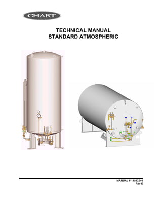
  • 9. 5 2 VESSEL INFORMATION Although vessels may vary in piping and plumbing details, some general comments on configuration and operation can be made. 2.1 RECEIVING CHECKPOINTS 1. Check braces, skids, wooden chocks, and other shipping supports. Damage or deformation would indicate the possibility of mishandling during shipment. 2. Examine welded or brazed joints on plumbing for cracks or deformation, especially near valves and fittings. 3. Check points where pipes exit the tank for cracks or breaks. 4. Check relief valves and burst discs for dirt or damage. 5. Check pressure within vessel on PI-1. If pressure is zero, extra precautions against contamination and impurities must be taken. 6. Examine the 5g impactograph. If it has sprung, damage may have occurred during shipment. Notify your company’s tank specialist and/or CHART. 7. Check the container vacuum. a) If warm vacuum for "NC" models is above 20 microns, consult factory. 2.2 VACUUM CHECK PROCEDURE CAUTION: UNAUTHORIZED CHANGING OF THE VACUUM PROBE WILL VOID VESSEL WARRANTY. 1. The standard CHART vacuum probe is a Teledyne-Hastings DV-6R probe. Select a compatible instrument to read the output of the vacuum probe. 2. Remove the rubber cap on probe outlet to expose contact. Note .that probe housing need not be opened to do this. 3. Plug the instrument to the probe and calibrate the instrument. Chapter 2
  • 10. 6 4. Open the vacuum probe isolation valve. Wait for 5 minutes and take vacuum reading. Note that valve handle protrudes through protective housing and can be turned without opening the housing. 5. Close the isolation valve and take a second reading. Monitor the rate of rise in vacuum probe with isolation valve closed. If the vacuum continues to rise at a constant rate, it is possible that the probe assembly is leaking. Consult the factory. 6. Verify that the isolation valve is closed. 7. Replace the rubber probe cap. Compare the vacuum reading obtained now to reading taken prior to shipping. 2.3 PHYSICAL DESCRIPTION A Chart vessel is designed for long-term storage of cryogenic liquefied gases under pressure in the range of 5 PSI (0.4 kg/cm2) to the MAWP (Maximum Allowable Working Pressure). Operation of the station can be fully automatic with the unit’s regulator system set to maintain preset pressure and flow conditions into a customer’s pipeline. While hardware may vary slightly from model to model, each unit essentially performs the same functions. The vessel is comprised of an alloy steel inner tank encased in an outer carbon steel vacuum shell. The insulation system between the inner and outer containers consists of composite insulation and high vacuum to ensure long holding time. The insulation system designed for long-term vacuum retention is permanently sealed at the factory to ensure vacuum integrity. The units have a tank pressure relief device, which is set at the factory. As a secondary pressure relief device, the container is further protected from over-pressurization by a rupture disc. The bursting disc will rupture completely to relieve inner tank pressure in the event the tank relief valve fails and pressure exceeds the rupture disc setting. The vacuum space is protected from over-pressurization by use of a tank annulus rupture disc assembly. Pressure relief devices used on Chart vessels designed for the U.S. specifications meet the requirements of CGA Pamphlet S1.3, “Pressure Relief Device Standards, Part 1, for Stationary Vessels.” The stations are leg mounted. Lifting lugs are secured to the bottom head and to the top head of the container. The lifting lugs are provided to facilitate handling. Moving requires the use of a crane and adherence to specific rigging instructions, which may vary from vessel to vessel. Some Chart vessels cannot be lifted with one hook only. Controls Used To Operate The System Are Mounted Under And On The Sides Of The Customer Station. The Pressure Gauge And Liquid Level Gauge Are Located At Eye Level On The Container For Ease Of Viewing.
  • 11. 7 Single Regulator System Single regulator system has a single regulator, which doubles as an economizer regulator and a pressure building regulator. The regulator in the economizer circuit automatically allows vapor space gas to be introduced preferentially into the final line or gas use circuit when the customer station pressure exceeds the regulator setting. The pressure building circuit is responsible for maintaining a minimum set pressure in the vessel. Dual Regulator System Dual regulator system has two regulators, which has an economizer regulator and a pressure building regulator. The regulator in the economizer circuit automatically allows vapor space gas to be introduced preferentially into the final line or gas use circuit when the customer station pressure exceeds the regulator setting. The pressure building circuit is responsible for maintaining a minimum set pressure in the vessel The normal operating pressure range of a vessel is from 60 PSI to approximately 175 PSI. Operating pressure can be increased or decreased as desired by adjusting the regulator, for vessels requiring a different range the PB/Econo regulator spring may be changed. 2.4 OPERATING DESCRIPTION Vessel operation is governed by the pressure build-up system and the economizer system. The pressure build-up system and the economizer system may be combined into a single regulator system for more effective low withdrawal operations. 2.5 PRESSURE BUILD-UP SYSTEM The pressure build-up system consists of an ambient air vaporizer and pressure building regulator. When tank pressure becomes lower than the set point of the pressure building regulator, the regulator will open. As a result, liquid will be able to flow through the vapor trap in the annulus, through the isolation valve and regulator to be expanded to vapor in the pressure building coil. The vapor accumulates in the inner tank vapor space to increase pressure. This flow continues until inner tank pressure is equal to regulator setting. When the pressures are equal, the regulator closes. This system thus automatically maintains station pressure as required. ** NOTE: Upon tank installation. The nuts mounting the PB coil (PBC-1) to the respective brackets must be loosened ½ - ¾ turns to allow for expansion & contraction.
  • 12. 8 2.6 ECONOMIZER SYSTEM The economizer system allows the excess gas, which accumulates in the vapor space during periods of low or no use to be consumed preferentially, in effect, it acts like an adjustable in-line relief valve, venting the tank into the customer use line. When vessel pressure is high, above the set point of the regulator, it opens. This allows gas, which flows more easily than the liquid, to flow out of the vapor space, through the isolation valve, regulator, and finally back into the tank to connect to the gas use line. This preferential flow continues until the regulator closes. The single regulator is designed to automatically set the economizer circuit to regulate at 7 PSI (0.5 kg/cm2) higher than that of the pressure building circuit. On dual regulator systems the preset economizer regulator is set at 20PSI (1.4kg/cm2). 2.7 OPERATOR QUALIFICATIONS Chart Stations are designed for safe and simple operation. The operator is expected to be knowledgeable of the nature of the gas (es) with which he is working, as well as all applicable safety requirements. This manual contains several chapters dealing with Operating instructions, Handling Instructions, and Maintenance Procedures. To fully understand these procedures, we recommend the operator first become familiar with controls and indicators.
  • 13. 9 3 CONTROLS Chart cryogenic container operating procedures specify that the operator shall be familiar with all controls and indicators as well as safety considerations. The following controls and indicators should be located and identified on the vessel prior to filling or putting the vessel into operation. For a list of controls and indicators, See Process & Instrument Diagram in Section 8. Chapter 3
  • 14. 10 4 FILLING PROCEDURES This chapter provides the initial fill, gas use, liquid delivery, and refilling procedures for the vessel described in this manual. Before performing any of the procedures contained in this chapter, become familiar with the location and function of the controls and indicators. 4.1 INITIAL FILL The initial fill is usually performed on a warm vessel, one that has not been in use for an extended period. The warm container must be purged to ensure product purity. When preparing the tank for filling or when changing service, the following items should be considered: 1. The vessel should be inspected for possible damage or unsuitability for intended use. If damage is detected (e.g. serious dents, loose fittings, etc.) remove the unit from service and perform repairs as soon as possible. 2. The vessel may be filled by pumping or pressure transfer. If vessel pressure is at least 50 PSI (3.5 kg/cm2) less than the maximum allowable pressure of the supply unit, liquid may be transferred by pressure transfer. If the normal working pressure of the station is equal to or grater than the maximum allowable pressure of the supply unit, liquid must be pumped into the tank. 3. To remove the moisture or foreign matter from the tank or tank lines, the vessel must be purged. Use a small amount of new product for purging when changing service and a small amount of the same product if the purge is to ensure purity or remove contaminants. 4. When changing service, the approved CGA (or other keyed) fitting will have to be installed for connection FC-1. Chapter 4
  • 15. 11 Table 1 Vessel Purging Procedure STEP NUMBER Purging Procedure CAUTION The maximum purge pressure should be equal to 50 percent of the maximum operating pressure of the tank or 30 PSI (2.1 kg/cm 2 ), whichever is less. The maximum purge pressure should be determined before starting the purge operation. To prevent drawing atmospheric contaminants back into the tank, a positive pressure of at least 5 PSI (0.4 kg/cm 2 ) must always be maintained in the tank. Attach the source of liquid purge to the fill connection (FC-1). 1 Close all valves except the pressure build-up valves (HCV-3, HCV-11) and liquid level gauge vapor phase and liquid phase shutoff valves (HCV-8, HCV-10). 2 NOTE The pressure building/economizer regulator or pressure building regulator in the dual regulator system (PCV-1) is normally set to build pressure to 120 PSI. When this pressure is used as the purge pressure, DO NOT adjust the regulator adjusting screw. When a solenoid valve is used to control the pressure building circuit, it must be energized. Open hose drain valve (HCV-7), and allow source to vent through hose. Vent until slight frosting appears on hose. Close hose drain valve (HCV-7). 3 Open the bottom fill valve (HCV-1) enough to allow liquid to flow slowly into the tank through the bottom fill line. The gradual flow enables the liquid to vaporize in the line and pressure buildup coil and slowly build up pressure in the inner tank. 4 Shut off the liquid supply source when the pressure in the tank reaches the maximum purge pressure as indicated on tank pressure gauge (PI-1). 5 Open the fill line drain valve (HCV-7) slowly to avoid splashing of the liquid. Drain all liquid from the tank. The appearance of gas (vapor) at the drain indicates that all liquid has been drained. 6 Close drain valve (HCV-7) and bottom fill valve (HCV-1). 7 Open the liquid level gauge equalization valve (HCV-9) to prevent damage to the gauge before closing the liquid level gauge vapor phase and liquid phase shut-off valves. When all liquid is drained, close the liquid level gauge vapor phase and liquid phase shut-off valves (HCV-8, HCV-10). 8 Loosen the unions on either side of the liquid level gauge (LI-1). Both the upper and lower liquid level gauge valves (HCV-8, HCV-10) should be opened wide and the gas streams visually checked for signs of moisture. Provided no moisture is observed after blowing the lines for approximately two minutes, both valves should be closed. If moisture is observed in the gas stream, the gas should be discharged until it is clear of all moisture.
  • 16. 12 STEP NUMBER Purging Procedure 9 NOTE A careful check for moisture in the phase lines will ensure trouble free operation of the liquid level gauge. Due to their small diameter, gauge lines are easily plugged by ice. 10 Open the vapor vent valve (HCV-12) and full trycock valve (HCV-4). The top fill valve (HCV-2) will have to be vented by opening hose drain valve (HCV-7). 11 Repeat purge procedure 2 through 6 and 10 at least three times to ensure product purity. 12 Reconnect the liquid level gauge (LI-1), open the liquid level control valves (HCV-8, HCV-10), then close the by- pass valve (HCV-9). 13 After purging the tank, but before filling, verify that the following valves are open or closed as indicated. Valve Bottom fill valve HCV-1 Top fill valve HCV-2 Vapor vent valve HCV-12 Full trycock valve HCV-4 Liquid level gauge equalizing valve HCV-9 Product supply valve HCV-13 Pressure building inlet/outlet valves HCV-3/HCV-11 Economizer isolation valve HCV-17 Liquid level gauge liquid phase valve HCV-10 Liquid level gauge vapor phase valve HCV-8 Position Closed Closed Closed Closed Closed Closed Closed Closed Open Open
  • 17. 13 Table 2 Initial (Warm Tank) Filling Procedure STEP NUMBER Initial (Warm Tank) Filling Procedure 1 Purge tank to assure product purity 2 Verify that the contents of the supply unit is the proper product to be transferred. 3 Verify that all valves except liquid phase-high (HCV-10) and gas phase-low (HCV-8) are closed. 4 Connect the supply unit transfer hose to tank fill connection (FC-1). NOTE Cool down the transfer hose prior to filling by opening hose drain valve (HCV-7) and venting the supply unit through the hose for approximately three minutes. Close drain valve (HCV-7). 5 Open bottom fill valve (HCV-1) slowly. If a pressure transfer is to be made, allow pressure to build up in the liquid supply unit until it is at least 50 PSI (3.5 kg/cm 2 ) higher than station pressure. Open the discharge valve on the supply unit to begin flow. (or) If a pump transfer is to be made, make the required connections to the pump. Open the supply unit transport discharge valve slowly. Maintain pump discharge pressure from 50 PSI (3.5 kg/cm 2 ) to 100 PSI (7.0 kg/cm 2 ) higher than the tank pressure. Fill slowly. 6 Monitor pressure in tank during filling. If pressure rises above supply pressure, or near relief valve pressure, the tank may have to be vented through the vapor vent valve (HCV-12), should pressure continue to rise, the fill may have to be interrupted to allow pressure to drop. 7 Monitor liquid level contents gauge (LI-1). When the gauge indicates approximately three-quarters full, open full trycock valve (HCV-4) 8 When liquid spurts from full trycock valve (HCV-4), immediately stop fill at the supply source and close full trycock valve (HCV-4). 9 Close bottom fill valve (HCV-1). 10 Drain residual liquid in the fill hose via drain valve (HCV-7). 11 Relieve fill hose pressure by loosening the hose at fill connection, then disconnect the hose. It is recommended that the fill hose be allowed to defrost to prevent moisture from being drawn inside the hose.
  • 18. 14 Table 3 Vessel Refilling Procedure STEP NUMBER Vessel Refilling Procedure 1 NOTE Filling a cryogenic vessel through the bottom tends to raise pressure in the vessel as gases in vapor space are compressed. Filling through the top tends to lower pressure as gases in head space are cooled down and re- liquefied. 2 Verify that the contents of the supply unit is the proper product to be transferred. 3 Verify that the bottom and top fill valves are closed (HCV-1, HCV-2). 4 Verify minimum required operating pressure in vessel. 5 Verify that all other valves are in normal operating positions. 6 Connect the supply unit transfer hose to tank fill connection (FC-1). 7 NOTE Cool and purge down the transfer hoses prior to filling by opening hose drain valve (HCV-7) and the supply unit discharge valve for approximately three minutes or until hose begins to frost. Close drain valve (HCV-7). 8 Open top fill valve (HCV-2) completely. If a PRESSURE TRANSFER is to be made, allow pressure to build up in the liquid supply unit until it is at least 50 PSI (3.5Kg/cm 2 ) higher than station pressure. Open the discharge valve on the supply unit to begin flow. (or) If a PUMP TRANSFER is to be made, make the required connections to the pump. Open the supply unit transport discharge valve slowly. Close pump circulating valve slowly, so as not to lose pump prime. Maintain pump discharge pressure from 50 PSI (3.5 kg/cm 2 ) to 100 PSI (7.0 kg/cm 2 ) higher than tank pressure. 9 Monitor pressure in vessel as indicated. If pressure begins to drop to near the minimum operating pressure, begin to open bottom fill valve (HCV-1), and throttle top fill valve (HCV-2), until pressure stabilizes. 10 Monitor liquid level contents gauge (LI-1). When the gauge indicates approximately three-quarters full, open full trycock valve (HCV-4). 11 When liquid spurts from full trycock valve (HCV-4), stop fill at the supply source and close full trycock valve (HCV- 4). 12 Close tank fill valves (HCV-1, HCV-2). 13 Drain residual liquid in the fill hose via drain valve (HCV-7). 14 Relieve fill hose pressure by loosening the hose at the fill connection, and then disconnect the hose
  • 19. 15 5 WITHDRAWAL PROCEDURES This chapter provides general guidelines for product decanting in either gaseous or liquid form for the vessel described in this manual. Before performing any of the procedures contained in this chapter, become familiar with the location and function of the controls and indicators. N O T E When using a vessel for gaseous service, a free standing vaporizer will have to be installed between the Gas Use connection and a final line pressure regulating system. 5.1 LIQUID DELIVERY Table 4 Liquid Withdrawal Procedure STEP NUMBER Liquid Withdrawal Procedure 1 Connect customer line liquid withdrawal connection (C-1). 2 Verify that all valves except gauge liquid phase valve (HCV-10) and the gauge gas phase valve (HCV-8) are closed. 3 Observe pressure building regulator/economizer regulator or pressure building regulator in the dual regulator system (PCV-1) setting as indicated on the station pressure gauge (PI-1). If station pressure is too high, open vent valve (HCV-12) to relieve excessive gas. It is possible that regulator springs will require changing for lower operational pressure. 4 Open liquid withdrawal valve (HCV-18) slowly to begin liquid flow. 5 Once the desired amount of liquid has been delivered, close the liquid withdrawal valve (HCV-18). Chapter 5
  • 20. 16 5.2 GAS DELIVERY Table 5 Gas Withdrawal Procedure STEP NUMBER Gas Withdrawal Procedure 1 Connect customer line to vessel gas use connection (VAP) or to the optional final line connection if used. 2 Verify that all valves except gauge liquid phase (HCV-10) and gauge gas phase (HCV-8) are closed. 3 Open product supply valve (HCV-13), pressure building inlet valve (HCV-3), PB outlet valve (HCV-11), and economizer shut-off valve (HCV-17) to start gas flow. At this time, final line pressure gauge will be indicating pressure in the customer line and the system will automatically deliver gas until stopped, or vessel is empty. 4 The liquid regulator will not open until the set pressure is reached, thus preferentially drawing vapor off the head space. Once the required amount of product has been delivered (or to close the tank down for an extended period of time), stop gas flow by closing gas use valve (HCV-13). The operation of an Chart unit is completely automatic, valves need to be opened and closed only during filling and during major maintenance. 5 Normal operating valve position for a VS unit are as follows: Bottom fill valve HCV-1 Top fill valve HCV-2 Vapor vent valve HCV-12 Full trycock valve HCV-4 Liquid level gauge equalizing valve HCV-9 Hose drain valve HCV-7 Product supply valve HCV-13 Pressure building inlet/outlet valves HCV-3/HCV-11 Economizer isolation valve HCV-17 Liquid level gauge liquid phase valve HCV-10 Liquid level gauge vapor phase valve HCV-8 Closed Closed Closed Closed Closed Closed Open Open Open Open Open 5.3 REGULATOR ADJUSTMENTS N O T E : To field set or adjust regulators quickly the vessel must preferably be a full tank. Under normal circumstances, the system does not require adjustment. However, it may be necessary to change regulator settings to obtain either higher or lower pressure setting within the range of the factory installed springs, at the time of starting up a vessel. It is good practice to verify set points during an initial fill. The adjustments which follows are required to “final set” the regulator following spring replacement, or after completing valve repairs which required disassembly and reassembly.
  • 21. 17 Single Regulator System The economizer regulator circuit will automatically be set 7 PSI (0.5 kg/cm2) higher than pressure building regulator. The pressure building regulator should be set approximately 20 PSI to 40 PSI higher than the desired delivery pressure. Detailed regulator adjustment procedures are provided in tables. Dual Regulator System The economizer regulator is normally set 20 PSI (1.4 kg/cm2) higher than pressure building regulator. The pressure building regulator should be set approximately 20 PSI (1.4 kg/cm2) to 40 (2.8 kg/cm2) PSI higher than the desired delivery pressure. Detailed regulator adjustment procedures are provided in tables. Table 6 Pressure Building Regulator Adjustment STEP NUMBER Pressure Building Regulator Adjustment 1 This procedure is best performed with a completely full tank, so that all changes in adjustment of the pressure building regulator will be reflected rapidly. Observe reading on pressure gauge (PI-1). If pressure is lower than desired set point of pressure building regulator/economizer regulator (PCV-1), proceed to Step 2; if higher, proceed to step 3. 2 If tank pressure is below the desired setting, loosen the pressure screw lock nut on the regulator. With PB Inlet and PB Outlet valves (HCV-3, HCV-11) open, gradually open regulator by turning the pressure screw (clockwise) to build tank pressure to the desired setting. Note that the pressure screw should be adjusted in small increments, allowing sufficient time for tank pressure to stabilize each time the screw is turned. The tank can be considered stabilized when no frost is found on the pressure building circuit. This reduces the possibility of over-shooting the desired pressure, which would in turn, require partial tank blow-down via the vent valve (HCV-12). Tighten lock nut on regulator, and return vessel to normal service. 3 If the tank is above the desired setting, open vent valve (HCV-12) to vent excess gas. Should pressure continue to rise above the desired level, proceed to step 4. 4 Again vent excess gas by opening vent valve (HCV-12). Reduce pressure until tank pressure gauge (PI-1) indicates a reading of 10 PSI (0.7 kg/cm 2 ) below the desired setting. Loosen set screw on PB regulator/economizer valve (PCV-1), and proceed to Step 2, gradually decrease tank pressure by adjusting the pressure screw (counter clockwise ).
  • 22. 18 6 VESSEL HANDLING INSTRUCTIONS Figures 1 and 2 depict two methods of handling vessels during installation. The handling method pictured in Figure 2 uses two cranes to place the tank. The two-crane method is the safer, and thus, more preferred method of installing the vessel. The alternate method of installation uses a single crane. This method is pictured in Figure 2. Chapter 6
  • 23. 19 FIGURE 1, TWO-CRANE INSTALLATION METHOD FIGURE 2, SINGLE-CRANE INSTALLATION METHOD
  • 24. 20 6.1 VESSEL TIE DOWN GUIDELINES Chart Industries, Inc. Vessel Tie Down Guidelines 3/5/99 PURPOSE: TO BE GIVEN or SHOWN TO DRIVERS PRIOR TO LOADING IF POSSIBLE. • Unless otherwise specified by customer, the tank should be orientated with the plumbed head pointing backward. The plumbing is less likely to be damaged during shipping in this orientation. • Place supports or saddles on the head-shell seam, never in the middle of the head. • Using appropriately sized element, tie the vessel to the bed of the trailer at the lifting lugs on the top of the vessel and at any lug clearly marked “Tie Down Only”. • If no lugs exist on the bottom portion of a vertical tank, tie the vessel to the bed of the trailer at the mounting holes on the leg pad. Attach elements to the vessel as close to the head as possible. If possible, avoid attaching chains to the outer part of the leg. • A minimum of eight elements should be used to secure any vessel. The elements should be situated such that the tank cannot slide or roll in any direction. • Straps can cause damage to the tank finish. Avoid using straps to secure the vessel. • Under no circumstances should a chain, strap, or other tie down equipment that may damage the tank finish, come in direct contact with the outer shell of the vessel. Use rubber pad, corrugated cardboard or a similar material to protect the tank in areas where contact may occur. The trucker is responsible for providing these materials when required. • If additional blocking is required due to placing the vessel partially over the drop section of the trailer, the trucker is responsible for providing that blocking. Figure 1 below shows a side view of an acceptable element configuration for a conventional CHART vertical vessel. Blocks or SaddlesChains Chains A Figure 2 - Vertical Rear View Figure 1 - Vertical Side View Figure 3 - Vertical Frontal View Figures 4 and 5 below show side and end views of a horizontal tank with tie down lugs on the saddle supports. The element configuration shown is acceptable for this type of vessel. If a tank is not equipped with tie down lugs on the saddle supports, use the holes in the saddle supports as tie down points. Use a chain configuration similar to the figure below. Figure 4 - Horizontal Side View Figure 5 - Horizontal End View
  • 25. 21 CABLE AND CHAIN TABLE Tank Size (gal) Typ. Vessel Weight (lbs) Maximum Force in Element (lbs) Recommended Cable Recommended Chain 1500 10000 17800 (1) ½” IWRC 6X19 (2) ½” Transport Grade 7 3000 17000 30600 (1) ¾” IWRC 6X19 (3) ½” Transport Grade 7 6000 30000 53900 (1) ¾” IWRC 6X19 (2) 7/8” Alloy Grade 8 9000 45000 66200 (2) ¾” IWRC 6X19 (2) 7/8” Alloy Grade 8 11000 54000 79400 (2) ¾” IWRC 6X19 (3) 7/8” Alloy Grade 8 13000 63000 92700 (2) ¾” IWRC 6X19 (3) 7/8” Alloy Grade 8 15000 72000 106000 (2) ¾” IWRC 6X19 (3) 7/8” Alloy Grade 8 This table shows approximate Chart tank sizes and weights. Tank sizes and volumes are based off of a standard 400 psi tank. Actual Tank weights may vary. Consult the data plate for the actual tank weight. The maximum force in any element is found from the weakest element on the vertical tank tie down configuration (Element "A"). If element "A" exceeds a 45 degree angle from horizontal the force in the element will exceed the value indicated in the table. ** IT IS THE DRIVERS RESPONSIBILITY TO SECURE LOAD IN ACCORDANCE WITH DOT REGULATIONS.
  • 26. 22 7 GENERAL This chapter contains vessel maintenance information, including troubleshooting and repair procedures. Before performing any of the procedures in this chapter, be sure you are familiar with the location and function of controls and indicators discussed in other chapters. 7.1 MAINTENANCE 7.1.1 COMPATIBILITY AND CLEANING It is essential to always keep the vessel clean and free of grease and oil. This is particularly important for units used in nitrogen and argon service since the temperature of liquid nitrogen or argon is below the liquefaction temperature of air; thus making it possible to condense liquid oxygen from air on the piping and vaporizer surfaces. When replacing components, use only parts that are considered compatible with liquid oxygen and have been properly cleaned for oxygen service. (Refer to CGA Bulletin G4.1 “Equipment Cleaned for Oxygen Service”.) Do not use regulators, fittings, or hoses that were previously used in a compressed air environment. Only oxygen compatible sealants or virgin Teflon tape should be used on threaded fittings. All new joints should be leak tested with oxygen compatible leak test solution. When de-greasing parts use a suitable solvent for cleaning metallic parts. 7.1.2 PERIODIC INSPECTION In order to maintain a cryogenic vessel in good operating condition, certain system components should be inspected on a periodic basis. Those components requiring periodic inspection are listed in this manual. In vessels being operated in areas having extreme hot or cold climates, inspection intervals should be shortened. 7.1.3 SOLDERING Before performing any soldering work, always exhaust oxygen from oxygen lines and purge with nitrogen gas. Verify that lines are inert. Chapter 7
  • 27. 23 7.1.4 VACUUM INTEGRITY These vessels are equipped with vacuum thermocouple gauge tubes and vacuum integrity may be tested with a vacuum meter. Deterioration or loss of vacuum will be apparent by cold spots, frost, or condensation on the jacket, or evidenced by abnormally rapid pressure buildup. Unless one of these conditions is evident, the vacuum level should not be suspected. In the event one of the above conditions exist, contact the factory for advice on vessel vacuum testing. 7.2 TROUBLESHOOTING The Table 10 provides some troubleshooting procedures. The table is arranged in a Trouble/ Probable Cause/Remedy format. Note that probable causes for specific problems are listed in descending order of significance. That is, check out the first cause listed before proceeding to the next. Repair procedures required, as listed in the remedy column, may be found in the Repair portion of this chapter. Perform procedures in order listed and exactly as stated (Refer to drawings as required to locate system components identified in the troubleshooting guide.) 7.3 REPAIR C A U T I O N : Plumbing should always be allowed to return to ambient temperature before repair work is performed. Vent or drain the vessel as necessary before replacing any component(s) exposed to pressure or to cryogenic liquid. When repair of damaged components is required (in those instances when a spare part is not readily available), follow the instructions below.
  • 28. 24 When disassembly of an assembly is required, removed parts should be coded to facilitate reassembly. Reassembly of components should always be performed in the reverse manner in which they are disassembled. Parts removed during disassembly should be protected from damage, thoroughly cleaned, and stored in protective polyethylene bags if not immediately reinstalled. Clean all metal parts with a good industrial cleaning solvent. All rubber components should be washed in a soap and warm water solution. Air dry all cleaned parts using an oil-free, clean, low-pressure air source. Before reassembly, make sure that all parts are thoroughly cleaned and have been degreased. Cleaning will prevent valves and regulators from freezing while in service and prevent contamination of the liquid product. When removing components from a vessel remember to always plug pipe openings as soon as they are exposed. Plastic pipe plugs of a clean plastic film may be used for this purpose. 7.4 VALVE REPAIR When a defective valve is suspected, remove and repair the assembly as described in this manual. If a valve is leaking through the packing, tighten the packing nut first to see if the leakage will stop before removing the valve. Packing is best tightened when the valve is warm. If a safety relief valve fails, the defective assembly should be discarded and a new valve installed. N O T E : Globe valves used on containers vary in tube size from ¼” to 2”. While internal valve components may vary from valve to valve, the functional operation and repair procedures for these valves are the same.
  • 29. 25 Table 7 Valve Repair STEP NUMBER PROCEDURE 1 2 3 4 5 6 7 NOTE Unless valve component parts are available in inventory, a defective valve should be replace with a new assembly. Release pressure in the vessel by opening vent valve (HCV-12). Remove the valve seat assembly. Disassemble the valve and inspect all piece parts Clean all metallic parts with a good industrial cleaner, and all rubber & teflon parts in a warm water and soap solution. Air dry all components using a clean low pressure air source. Replace all worn, deformed or damaged parts. Repack the valve. Either preformed or twisted Teflon filament packing can be used. When using twisted Teflon filament packing, untwist Teflon and use only a single strand. Pack Teflon tightly; otherwise, moisture can get into the valve and freeze when the valve is cold. Reassemble the valve. Make sure that mating surfaces are clean and properly seated. If the repaired valve is not to be reinstalled immediately, seal it in a polyethylene bag for storage. Apply a label to the bag such as "CLEAN VALVE. DO NOT OPEN BAG UNLESS UNIT IS TO BE INSTALLED."
  • 30. 26 7.5 REGULATOR REPAIR When a defective pressure building regulator/ economizer regulator or final line regulator is identified, remove and repair the units as detailed in this manual. N O T E : Replacement regulators should be obtained from Chart to ensure compatibility. Table 8 General Regulator Repair STEP NUMBER PROCEDURE 1 2 3 4 5 6 7 8 9 10 NOTE Unless regulator component parts are available in inventory, a defective regulator should be replaced with a new assembly. Release pressure in the vessel by opening vent valve (HCV-12). Depressurize the regulator. Single Regulator System a) For the pressure building/economizer regulator (PCV-1), this is accomplished by closing the pressure building inlet valve (HCV-3), the pressure building outlet valve (HCV-11), and the economizer isolation valve (HCV-17), and by loosening line relief valve (TSV-3). This relieves pressure on both the upstream and downstream sides of the regulator. Dual Regulator System b) For the pressure building (PCV-1) or economizer regulator (PCV-2), this is accomplished by closing the pressure building inlet valve (HCV-3), the pressure building outlet valve (HCV-11), and the economizer isolation valve (HCV-17), and by loosening line relief valves (TSV-3 and TSV-4). This relieves pressure on both the upstream and downstream sides of the regulators. c) For the final line regulator, this is accomplished by closing the two final line regulator isolation valves. It is possible that the body of the regulator is permanently installed in the vessel; in this case the seats, domes, pistons, springs, gaskets, etc. can be removed and replaced. Disassemble the regulator, making sure to identify all piece parts removed. Inspect all parts for wear, deformation, nicks, or damage. Replace all gaskets and O-rings. Clean all metal parts with an industrial cleaning solvent. Air dry with a clean, low-pressure air source. Reassemble the regulator in the reverse order of disassembly. Bench test the rebuilt unit to make sure that it actuates properly at the set pressure. The pressure builder/economizer and final line regulators close to regulate downstream pressure. If the regulator is to be reinstalled on a vessel, do so as soon as possible following repair. If it is to be returned to inventory, seal the unit in a polyethylene bag for storage. Apply a label to the bag such as "CLEAN REGULATOR, DO NOT OPEN BAG UNLESS UNIT IS TO BE INSTALLED. " Pressurize the regulator by opening the applicable pressure building and isolation valves. Allow pressure to build up in the system and verify the reliability of the rebuilt unit.
  • 31. 27 7.6 GAUGE REPAIRS Since a special instrument is normally required for making gauge repairs. It is advised that a defective gauge be replaced with a new unit and the defective one returned to your local Chart distributor or to the factory for repairs. However, before replacing a gauge there are a number of checks that can be performed. C A U T I O N : Before removing (or calibrating) the tank pressure gauge or liquid level gauge, make sure gauge isolation valves are closed and that the equalizing valve is open. The major cause of gauge malfunction is a leakage in the gauge line. Therefore, as a first check, make certain that gauge lines are leak tight. Other gauge tests include: 1. Check gauge lines of obstructions. 2. Check leaky equalizer valve. 3. Ensure that connection lines are properly mated. 4. Verify that the gauge is properly zeroed. 5. Ensure that the pointer doesn’t stick. If the above checks fail to correct the problem, remove and replace the gauge. When returning the gauge to Chart for repair, indicate the nature of the difficulty experienced with the gauge in your letter of transmittal. 7.7 INNER TANK BURST DISC REPAIR The tank burst disc is a safety relief device that will rupture completely to relieve inner tank pressure in the event tank relief valve fails or is unable to accommodate sufficient flow. Due to changes in pressure in the vessel, the disc will flex, gradually harden, embrittle, and consequently rupture at a lower pressure. The following table serves to describe replacement of the inner vessel burst disc for vessels equipped with a dual relief system. In the event that a component needs to be replaced in the dual relief system, simply switch the selector handle to the other side of the safety system to allow routine maintenance and repair.
  • 32. 28 Table 9 Tank Burst Disc Replacement - Dual Safety System STEP NUMBER PROCEDURE 1 Switch selector valve (HCV-15) to other side, and depressurize the isolated side of the relief valve system, rather than venting vessel. 2 Remove burst disc (PSE-1) by opening HCV-16 if equipped. Or loosen PSE-1 allowing pressure to escape.. 3 Install new burst disc (PSE-1), making sure that mating surfaces are clean and properly seated. Use an oxygen compatible liquid thread sealant to prevent leaking.
  • 33. 29 7.8 TESTING AFTER REPAIR After making repairs requiring disassembly or part replacement, leak test all valves and piping joints that were taken apart and reconnected. Do not return the vessel to service until all leaks have been corrected or retested. Table 10 Troubleshooting PROBLEM POSSIBLE CAUSE DIAGNOSIS SOLUTION Excessive Tank Pressure Vessel 1. Inadequate vacuum 1. Take vacuum reading Consult factory *Vessel vents through relief valve frequently 2. Leaking pressure building/economizer regulator (PCV-1) 1. Line to PCV-1 frosted from tank to HCV-3, and beyond 1. Check adjustment 2. Repair or replace *Pressure remains above economizer set point 3. Economizer not operating (tank above economizer set pressure) 1. No frost evident on pipe to HCV-17 & PCV-1. 1. Check if HCV-17 open 4. Tank gauge (PI-1) in error 1. Compare with gauge of known accuracy 1. Replace 5. Low withdrawal rate 1. Frosting on economizer piping. No frosting on HCV-13 or Vap 1. Consult factory 6. Excessive shutdown time 1. User pattern 1. Replace vessel with more efficient model Failure to maintain set delivery pressure 1. Pressure builder not operational 1. PB Valve Closed 1. PB Valve Open *House pressure is low 2. Regulator set too low 1. No frosting on pipe to HCV-3, PCV-1 or PBC-1 2. Set pressure at or below final line pressure 1. Readjust 3. Cannot maintain pressure 1. HCV-3, PCV-1 always frosted 2. Withdrawal too high 1. Install higher capacity PB system-consult factory 4. Tank burst disc (PSE-1) ruptured 1. Flow can be felt at outlet of PSE-1 1. Replace 5. Piping leak 1. Leak is audible 1. Replace Erratic contents gauge reading 1. Needle is stuck 1. Tap gauge 1. Inspect pointer and bend if need be 2. Needle binds 1. Tap gauge repeatedly 1. Replace gauge 3. Needle does not adjust to "0" 1. Does not "0" when HCV-9 (equalizing valve) opened 1. Adjust 4. Leaky gauge lines 1. Reading does not correspond to use 1. Tighten lines and fittings 5. Incorrect span 1. Reading does not correspond to use 1. Reading does not correspond to use 6. Valves not opened 1. Needle stays at "0" 1. Equalization valve closed (HCV-9) 2. Isolation valves (HCV-8 and HCV-10) open 7. Reverse lines 1. Needle stays at "0" 1. Check stampings in gauge and vessel bottom "HP" corresponds to liquid phase 8. Plugged line 1. Needle pegs, or moves very slowly 1.Consult factory
  • 34. 30 PROBLEM POSSIBLE CAUSE DIAGNOSIS SOLUTION Leaking relief valve 1. Ice under/in seat 1. Valve reseats when warming up 1. Warm and dry valve to prevent moisture accumulation 2. Damaged seat 1. Valve does not re-seat 1. Replace valve Ruptured tank burst disc 1. Excessive pressure 1. Relief valve damaged 1. Replace disc and valve 2. Fatigue or corrosion 1. Environment 1. Replace disc Inability to hold vacuum 1. Improper vacuum gauge change (voids warranty) 1. Measure vacuum rise in gauge assembly 1. Consult factory 2. Internal/external leak 1. Vacuum rises in tank over short time 1. Consult factory 3. Corroded safety disk (PSE-3) 1. Visual on helium leak test 1. Replace and re-pump 4. Outgassing 1. Slow vacuum rise over long time 1. Re-pump 7.9 REGULATOR MAINTENANCE INSTRUCTIONS PBE-1: The Type PBE-1 regulator is designed for cryogenic service and combines the pressure building and economizer functions into one unit. In the Type PBE-1, the economizer function starts before the pressure build function stops. A restriction orifice limits the economizer output and prevents it from overpowering the pressure build function. PBE-2: The Type PBE-2 regulator is designed for cryogenic service and combines the pressure building and economizer functions into one unit. It is a direct acting, single seated, spring loaded diaphragm-type regulator. In the Type PBE-2, the economizer phase starts at the point at which the pressure build level is reached, thus assuring a smooth transition between the two functions. DUAL REGULATORS Dual regulators are designed for cryogenic service utilizing separate regulators for pressure building and economizer functions. This allows setting of greater pressure differences between these two regulated functions. OPERATING INSTRUCTIONS Adjusting the Delivery Pressure The regulator’s delivery pressure setting is adjusted by turning the adjusting screw at the top of the spring chamber after loosening the adjusting screw lock nut. To increase the delivery pressure, turn the adjusting screw clockwise (into the spring chamber). To decrease the delivery pressure, turn the adjusting screw counter-clockwise (out of the spring chamber). Tighten the adjusting screw lock nut after the adjusting has been made.
  • 35. 31 REPAIR KITS REGULATOR PART NUMBER REGULATOR SIZE MODEL KIT PART NUMBER 11490623 ¼” PBE-1 11656638 11490631 ½” PBE-2 11656700 2110032 ¼” A-32 9715652 2110072 ½” TYPE B 10620123 11640353 ½” G-60-HP 11656734 11049205 ¼” FRM 9715572 2111462 ½” FRM-2 HP 10620115 SPRINGS REGULATOR MODEL SIZE SPRING PART NUMBER RANGE (PSI) PBE-1 ¼” 10525193 10972348 75-175 150-350 PBE-2 ½” 5710131 10522363 11525371 10707392 20-75 25-125 100-200 150-250 A-32 ¼” 5710191 5710111 10525193 5710201 15-65 40-100 75-175 100-250 TYPE B ½” 5710131 10522363 11525371 10707392 20-75 25-125 100-200 150-250 G-60 ½” 5710431 5710371 5710411 0-7 5-70 100-400 FRM ¼” 5710031 5710191 5710111 10525193 5710201 2-25 15-65 40-100 75-175 100-250 FRM-2 ½” 5710301 200-400
  • 36. 32 7.10. NEW YORK CITY FIRE DEPARTMENT APPROVALS The City of New York Fire Department requires that vessels placed into service meet certain conditions for approval. The Certificates of Approval, stating the conditions are available upon request from the factory as manual addendums.
  • 37. 33 8 DRAWINGS Outline & Dimension VS-525-1500 C-11534201 VS-3000-6000 C-11517988 VS-9000-15000 C-11502954 HS-1500 C-11636688 HS-1500 W/SKID C-11721401 HS-3000-6000 C-11648591 HS-9000-15000 C-11653331 Process & Instrument Diagram (UNIT SPECIFIC)
  • 38. 34
  • 39. 35
  • 40. 36
  • 41. 37
  • 42. 38
  • 43. 39
  • 44. 40
  • 45. 41