2. By V. LEE OERTLE
HERE'S the going-est buggy a fellow
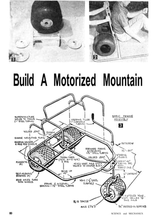
could want. It's wilderness transporta-tion
to delight the heart of the amateur
geologist, weekend prospector or straight-out
sportsman who's looking for rugged
wheels for rugged terrain. It can be built for
about $300 more or less—depending on how
many used parts can be substituted for new
ones—and a few weekends of work.
Your First Step will be to draw a full-size
cardboard pattern for the Goat's frame.
In doing so certain dimensions, especially
regarding clearances, should be borne in
mind. These include the size of the tires,
wheels and engine; the space the drive chains
and sprockets will require to clear the frame;
and your own individual requirements for
space and comfort.
The tires will be your biggest expense,
running roughly $120, with wheels, for three
complete ready-to-go units. The three tires
used on the Goat are Goodyear Terra-Tires
with bolt-on flanges (Fig. 1). These are
tubeless jobs that operate at air pressures of
from 1 to about 15 psi, depending on the
terrain. They enable the Goat to claw its way
MARCH, 1963 81
3. FIG. 5: Jack-shaft is section of
1" kart axle keyed to accept
sprockets. Note self-aligning
bearings on the bearing hangers.
FIG. 7: Split-axle power train permits more ground clearance under frame.
Also, the Goat will keep going if one jack-shaft-to-wheel chain breaks.
FIG. 6: Bearing hangers for jack-shaft
bolt to slotted braces so
hangers can be moved up or
down by loosening four 1/2" bolts.
over sand, mud, snow, rocks
and other obstacles that
would stop other vehicles
dead. Tire size for the Goat:
16x12—6R.
When you have made
your engine-compartment
measurements on your pat-tern
you can estimate the
Goat's overall length by sit-ting
down on the pattern at
the point where the seat will
be situated and drawing up
your legs to a comfortable
position. Then mark the spot behind your
heels and add 2 in. to allow room for the
seat-back cushion. Overall length of the Goat,
including the front wheel, probably will be
75 to 85 in., which is average.
Kart parts can be used almost exclusively
to make this type buggy. Standard-size parts
are quite cheap. Buy your materials from a
FIG. 8: Clamp piece of floor steel to frame to check 45° turning angle.
local kart shop or through a mail-order house
and you'll save money.
Frame. The frame is made of 1015-grade
cold-rolled steel tubing having a wall thick-ness
of .083 to .120 in. with an outside diam-eter
of 1-1/2-in. Instead of being all-welded it
is bent to shape following the full-size
pattern.
82 SCIENCE and MECHANICS
4. FIG. 9: Weld 16-gauge-steel floor to frame bottom.
Install crosswise so that scrap pieces can be used.
Check out your sketch by sitting down on
the pattern and trying to visualize the loca-tions
of steering tiller, seat back and wheels
(Fig. 2). If the sitting position seems
cramped, extend the front radius a little. And
make sure two persons can sit within the
sides of your pattern. Then take the pattern
to a tube bender.
The cost for the frame-bending job will
range from $15 to $25. The recommended
method for bending the frame is to have it
bent up in two sections, then joining the sec-tions
with a welded joint at the front of the
frame and another at the rear (Fig. 3).
After bending, check your frame against
the original pattern (Fig. 4) for any varia-tions
that may have resulted. Don't worry if
the dimensions are not precise (you can
allow for some error in both length and
width). The important thing is to make sure
the frame is aligned correctly fore and aft so
that the Goat will steer and track properly.
Superstructure. Any Goat you build will
require a superstructure to support the seats
and arm rests. This can be bent from smaller
tubing, such as 1-in. cold-rolled steel, then
welded in place.
Gear Ratios. To calculate your gear ratios
divide the number of teeth of the clutch
sprocket into the number of teeth on the
jack-shaft sprocket; for example: 12 into 36
equals a ratio of 3:1. Do the same with the
jack-shaft-to-axle sprockets; for example: 12
into 60 equals a 5:1 ratio. Now multiply the
clutch ratio by the axle ratio, as: 3:1x5:1
equals a 15:1 ratio—the same as was installed
on my own Goat. However, I recommend a
gear reduction of at least 20:1. This would
require the following six sprockets: (1) a
FIG. 10: Brake and throttle control rods are 1/4" steel.
Connector plates permit offsetting these controls.
CONNECTOR
PLATES LEAD
CONTROL POD
TO BRAKE
12-tooth sprocket on each end of the jack-shaft;
(2) a 60-tooth sprocket on each rear
axle; (3) a 48-tooth sprocket on the jack-shaft;
and (4) a 12-tooth sprocket on the
engine clutch.
Drive Chains. The jack-shaft-to-wheel
drive chains should be #40s. The engine-clutch
drive chains can be #35s.
Jack-Shaft. The jack-shaft (Fig. 5) is sim-ply
a section of old 1-in. kart axle. Such axles
are already keyed to accept standard sprock-ets
and brake systems. Use standard self-aligning
axle bearings to support the jack-shaft,
and bolt the flangettes onto standard
bearing hangers. The latter can be made ad-justable
using the simple sliding-bracket
arrangement shown in Fig. 6.
Split-Axle Power Train. By using a pair
of stubby axles instead of one long one the
Goat will have greater ground clearance and
fewer projections (Fig. 7). The parts needed
for one rear-axle assembly include axle, nut,
flangettes with self-aligning bearings, lock-ing
collar and chain sprocket. The axles are
suspended in the self-aligning bearings which
(Continued on page 120)
MARCH, 1963 83
5. Build a Motorized Mountain Goat . . . . (Continued from page 83)
in turn are supported by flangettes, the latter
bolted through steel bearing hangers welded
to the underside of the frame.
Both rear wheels have 1/4" x 1/4" keys cut
inside the flanges to permit keying to the
axles. The rear-axle sprockets are also keyed
to the axles so that when the jack-shaft
rotates, a drive chain turns the power
sprocket. Both rear axles are "live"; that is,
they rotate with the wheels. The front wheel,
on the other hand, turns freely in 3/4-in.
pressed-in bearings.
Steering. To determine your ground-clear-ance
requirements place the frame atop some
boxes at the desired height to see where the
front wheel will go (Fig. 8). When position-ing
this wheel, clamp a piece of floor-pan
steel temporarily to the underside of the
MATERIALS LIST-MOTORIZED
MOUNTAIN GOAT*
Amount Size & Description
. FRAME
30' (approx.) 1015-grade, l ' /2" od cold-roll steel tubing
25' (approx.) 1" cold-roll steel tubing (superstructure)
hardware, pipe suppliers
TIRE-WHEEL UNITS
3 Terra-Tires (with wheels) size 16x12—6R
Goodyear Tire & Rubber Co., Akron, 0.
Geneva Wheel Co., Geneva, 0. ($38.69 per unit)
GP Enterprises, 152 Huntington Dr., Monrovia
Calif. ($19.95)
ENGINE
1 Briggs & Stratton, 7-hp, 4-cycle power unit
SPROCKETS
2 12-tooth for each end of jack-shaft
2 60-tooth for each rear axle
1 48-tooth for jack-shaft
1 12-tooth for engine clutch
kart shops, mail order houses
REAR AXLES
2 split-axle power train
DRIVE CHAINS
2 #40s for lower-end installation
2 #35s, clutch-to-jack-shaft
kart shops, hardware
JACK-SHAFT
1 used kart axle with keyway; 1" dia., 3-4' long
STEERING
1 front axle; short section of 3/4" kart axle
1 front-wheel yoke; l-1/2" cold-roll steel tubing
1 tiller; 1" dia. chromoloy tubing (steering handle)
kart shops, hardware
CONTROLS
1 brake control; 3/8" dia., 16" long steel rod
1 throttle control; 3/8" dia., 16" long steel rod
kart shops, hardware
MISC.
kart shops
Other parts incl. clutch, steel-disk brake assembly, floor pan (16-ga.
sheet steel), self-aligning bearings (8—with hangers), flangettes,
gussets. controls and pedals ($10), and frame bending and welding
charges.
* Design of the Mountain Goat is such that considerable leeway is
afforded the builder in making innovations. For that reason this
Materials List need not be considered mandatory, since additions,
such as transmission, bumpers, etc., may want to be made by indi-vidual
builders.
frame to be sure there will be enough clear-ance
to permit the wheel a 45° turning angle
in both directions.
Make the U-shaped front-wheel yoke from
the same l-1/2-in. tube stock used for the
frame. Flatten out the end of the yoke's U and
drill holes through each to take, say, a 3/4-in.
axle. Now chop off a length of kart axle (with
keyway) and weld this onto the top of the
center block welded to the yoke. This piece of
axle stock will ride in the neck of the steering
sleeve. The sleeve can be of any heavy metal
having a minimum wall thickness of .125 in.
with an inside diameter of 1 in. It is welded
into position on the forward end, or exten-sion,
of the frame.
The tiller handle can be bent of 1-in. cold-rolled
or chromoly tubing, preferably the
latter. Weld a 2-in. piece of steering-sleeve
tubing to the base of the tiller so that it can
be slipped over the yoke shaft. Use set screws
to tighten it on.
Engine. Four-cycle engines provide the
best power in the low-gear ranges. Geared
down to 20:1, a 7-hp Briggs & Stratton mill
will drive the Goat, with two people aboard,
up anything short of a 45° grade. At this
ratio you'll get about 10 mph on hard flat-lands
and roads.
Jack-Shaft Bearing Hangers are welded
to the 1/8-in. steel plates forward of the en-gine
mounting plate. A slotted brace (Fig. 6)
under the hanger allows the jack-shaft to
be moved forward or back by loosening four
1/2-in. bolts. This adjustment is necessary for
the fitting, adjustment and removal of the
drive chains.
Floor Pan. Fabricate the floor pan from
standard-width 16-gauge steel. Run the strips
across the bottom of the frame (Fig. 9), weld
the seams and weld the edges to the bottom
of the frame's tubing. By running the floor
pan across instead of lengthwise you can get
away with using narrower scrap pieces and
avoid having to buy extra-wide sheet steel.
The Connectors to brake and throttle con-trols
can be lengths of 1/4-in. steel rod. Weld
2-in. steel connector plates onto the ends of
the rods to allow offset connections to be led
to the desired control. Simple gussets
welded to the frame serve to anchor the rods.
Also be sure the rods turn freely inside pre-drilled
holes. The brake-rod installation
shown in Fig. 10 is activated by a foot pedal.
Now slap on a coat of primer paint and
take your Goat out for a test run through the
country. You will find that your Terra-Tires
will take you over the sandiest terrain with-out
bogging down. The front-wheel steering
should give you excellent control with light
arm pressure. And you will discover that
your little 7-hp plant has all the spirit you
could desire. •
V"
120 SCIENCE and MECHANICS
6. How to build a vehicle
that will let you ride in
comfort where even walking
would be difficult—
The
Wheeled
By V. Lee Oertle
THE one place it makes no sense
to drive this handy little vehicle is
on the road. When the load ends,
it comes into its own. Unload its 200
pounds from station wagon or trailer,
crank up the geared-down, 4-1/2-hp. en-gine,
and it'll carry you just about any-where
you want to go—through country
lanes, cow pastures, swamps and bogs,
over out-of-the-way beaches, or deep into
the desert.
New fat tires are the secret of its go-anywhereness.
They're a full 12" wide
across the tread, 16" in diameter. This
broad, flat footing gives the buggy a
sure grip wherever you go. For sand or
soft earth, you carry only two pounds of
air in each tire. Where you need greatest
traction, fill them with water to add
weight.
Goodyear dealers can order the Terra-
Tires for you at about $35 each. Price
is expected to drop. Wheels are available
from Hadco Engineering Co., Los An-geles,
Calif., or from Geneva Wheel Co.,
Geneva, Ohio.
Gelling ready to roll. The two rear
wheels are keyed to a 1" axle. 60" long,
to provide a wide tread for stability on
hills. The ends of the axle are shouldered
to 3/4", threaded and slotted for the keys
that lock the wheels in place.
The front wheel is mounted on a yoke
—as on a tricycle. The three wheels stay
in contact with the most uneven ground,
eliminating any tendency for the frame
to twist. The single front wheel simpli-fies
construction and handling.
Chalk the outline of the frame on a
smooth floor, and sit down where you've
drawn the seat. If the dimensions given
Three-
Desert
Scout
7. LOAD THE BUGGY into a station
wagon to carry it over the road.
A couple of two-by-fours serve
as an unloading ramp at road's
end. A sprocket-and-chain drive
(below) steps up the 4-1/2-hp.
engine's torque, enabling it to
haul two people with ease.
don't suit your leg length, tailor the
buggy to your size by making the side
members shorter or longer.
Starting the buggy. Cut the frame
pieces from rectangular steel tubing. Fit
them together on the floor, mark them,
and take them to a welder. It cost me
only $18 to have the frame expertly heli-arced
together. The seat back, armrests,
rear-axle bearings, motor-mounting plate,
and jackshaft supports were also welded
in place at this time.
On a second visit, I had the floor pan,
steering sleeve, and bushings for the
brake and throttle arm welded to the
frame. These had been cut and fitted be-tween
visits to the shop.
I also had the welder bend the front-
8. MOUNT REAR WHEELS on axle and check inside
clearance before cutting frame parts. Rectan-gular
steel tubing was chosen for maximum
rigidity, but round tubing could be used.
SIMPLE TILLER steers front wheel. Sleeve is
welded in vertical position to front of frame,
braced securely with steel gussets. Telescoping
steering arm fits over tiller shaft.
wheel yoke from a length of husky 3/8"-
by-2" hot-rolled .steel. I held the 1" tiller
rod in position while he butt-welded it to
the center of the yoke. A steering arm of
l"-i.d. steel tubing is pinned to the tiller
with a bolt and wingnut. Bolt holes spaced
at intervals along the tiller permit ad-justment
of steering-arm length.
The 1" tiller rod turns in a sleeve
welded through a hole in the front of the
frame. Bearings were setscrewed to the
rod at each end of the sleeve.
The front wheel rolls on sealed bearings
pressed into the hub. It is mounted on a
1" axle bolted across the open end of the
yoke.
Adding the horses. Any four-cycle en-gine
in the 4- to 7-horsepower class will
drive the buggy efficiently. I found a good
used 4-1/2-hp. engine for $50.
JACKSHAFT between the engine
and rear axle allows fast chang-ing
of sprockets to suit a variety
of operating conditions. Disk
for the caliper brake is also
mounted on this shaft.
SPLIT-AXLE SPROCKETS speed
drive-ratio change-over. Seg-ments
of various diameters bolt
on hub keyed to axle. Two
sprockets can be mounted on
hub for use with double chain.
CALIPER BRAKE, sold in kart
shops, stops disk on jackshaft,
effectively braking both rear
wheels. Short linkage actuated
by a hand lever at side of buggy
operates the calipers.
9.
10. FLEXIBLE CABLE connects throttle control to car-buretor.
Compression spring slipped on cable
between housing and linkage returns carbu-retor
to idle when throttle is released.
TO CUSHION ANY JOLTS that aren't absorbed by
the pillow-like tires, thick foam rubber pads
the seat and back rest. Cover foam with plastic
or other durable upholstery material.
FOR ROUGH GOING, tires can be filled with wa-ter.
Use a tractor's valve fitting attached to a
garden hose. The extra weight provides greater
traction and reduces bounce.
A shoe-type clutch could be used but
might overheat when pulling over loose
turf and sand. A fluid clutch can
be bought from Bowlus Engineering,
Pacoima, Calif.
You can run drive chains direct from
the clutch to the rear axle, but this isn't
advisable. The use of a jackshaft provides
more flexibility in setting up drive ratios
and lets you mount the brake clear of
sand and water.
Kart shops stock a variety of caliper-type
brakes. Some work mechanically and
some are hydraulically assisted. I chose
the mechanical type for simplicity—a
narrow disk about 5" in diameter that is
mounted on the jackshaft. When the
brake is applied, a caliper squeezes
against the disk.
Riding soft. To absorb the shocks of
driving in rough country, double
sprockets and a double-row No. 35 chain
were used on the jackshaft and axle.
These I obtained from Bug Engineering.
Irwindale, Calif. Single sprockets and
chain were used between the engine and
jackshaft, since the fluid clutch smooths
out much of the impact.
By varying the number of teeth on the
axle and jackshaft sprockets, you can get
a wide range of drive ratios. For flat ter-rain
or beach sand, a 10:1 ratio will push
the buggy along at about 18 m.p.h. For
climbing and rough-country use, a 20:1
ratio will provide all the power you need;
but top speed will be between 8 and 14
m.p.h. Even though speed is reduced, the
extra power allows more fun. It's like
driving a bulldozer. You feel that no ob-stacle
can impede your progress. To
achieve this ratio, I used this combination
of sprockets: 13-tooth on the engine. 36-
tooth on the jackshaft, 10-tooth on the
output end of the jackshaft, and 72-tooth
on the axle.
Making it go. Controls are simple and
can be operated with one hand. Push
down on the lever—or pull it up—to apply
the brakes. Twist a motorcycle-type
throttle on the end of the lever to gun
the engine. The fluid clutch automatically
engages and disengages the engine from
the drive train.
A guard mounted over the sprockets
and chain is good insurance against acci-dental
injury, especially over rough
ground. This could be quickly shaped
from thin plywood or hardboard. • •
11.
12. Midget Sidecar for Junior's Sidewalk Bicycle
TO SEAT BOLT
CONSTRUCTION OF
Here's a simple bicycle sidecar that is
bolted to the bicycle at three points and
can be attached or detached in a few mo-ments.
Besides carrying a passenger, the
sidecar is handy on a newspaper route or
for delivery of packages. The simple frame
is made of 3/1-in. conduit, bent and welded SHEET XLE FASTENED
together, while the body is assembled by
screwing a piece of sheet metal onto dupli- and at the same time provide good solid
cate wood sides. Two rood cleats screwed surfaces for attaching the body to the frame
to the underside of the bottom give rigidity with conduit straps screwed in place.
Jig Aids in Truing Bicycle Wheel When Tools Are Limited
The cyclist or owner of a small shop who
but does not have the equip-ment,
wants to true or stripe a bicycle wheel oc-casionally,
will find this little jig the solution to
his problem. In use, the wheel is clamped
in a vise by the spindle, and the jig is at-tached
to the edge of the bench. In it can
be held a small block for truing the wheel,
or a brush for striping it.
Bicycle Handlebar Has Reflectors
One boy who used his bicycle at night
put red reflectors in rear ends of the han-dlebar
grips in addition to a large one on
the 'ear fender. To
install the rcflcc-tors,
rear ends of
grips are cut out,
leaving enough
mbber at the out- ,,
side to serve as a
retaining edge.
13. BY
GEORGE
JONES
HALF-SIZE
PACKARD
Recapture the romance of the horseless
carriage era! Be the man who owns one!
IT has been 63 years since the great-granddaddy of
this bright-red 1901 Packard roadster purred its
way down America's roadways. Our half-size version
should bring a twinge of nostalgia to MI's senior read-ers—
and delight the younger set.
Under the tonneau (that's the rear-deck lid, son)
there's a modern two-hp gasoline engine with chain
drive direct to the axle. Speeds up to 15 mph are pos-sible.
Designed to carry two youngsters in comfort, the
car also is sturdy enough to haul two adults. Right-hand
steering (as in the early days), an automatic
centrifugal clutch, a foot brake and hand accelerator at
your fingertips make operation of the vehicle a breeze.
It was on Aug. 13, 1898, that James Ward Packard
purchased the 12th car built by Alexander Winton. On
his trip home to Warren, Ohio, some 50 miles from the
Winton factory in Cleveland, the car broke down. The
incensed purchaser returned to the factory to complain
about his lemon and Alexander Winton told him, "If
you're so smart, Mr. Packard, why don't you build a
120 Mechanix Illustrated
15. HALF-SIZE
PACKARD
FRAME is cut from angle iron and welded
together upside down. Front and rear axle
and spring assemblies are bolted in place.
COMPLETED chassis and running gear with
the brake pedal, brake rod, pedal-return
spring, engine and drive assembly in place.
RIGHT front wheel detail shows steering
assembly—shaft, pitman arm, perch welded
to axle, drag link, tie rod and ball joints.
car yourself?" History has recorded the
results.
The first Packard was sold in January
1900. Almost immediately the reputa-tion
of Packard was secure. "Ask the
man who owns one" became a house-hold
phrase.
We hope the building of this replica
1901 Packard roadster will recapture
for you some of the romance and excite-ment
of the horseless-carriage era.
The body is made of plywood, the
frame of angle iron, with a minimum of
welding. You can purchase such hard-to-
make parts as wheels (aluminum
cast—16x1.75 with semi-pneumatic
tires) and hub caps, steering wheel,
pillow blocks (one-inch Fafnir), ball
joints and brake (Mercury strap). The
other parts, for the running gear, re-quire
but a small amount of machining.
Most of the construction can be ac-complished
in the home workshop.
[For a price list of parts and informa-tion
as to where they are available, send
a stamped, self-addressed envelope to
George E. Jones, Box 1243, Magnolia
Park Station, Burbank, Calif.']
Construction begins with the frame.
Have your steel supplier cut the two side
rails and three cross members to length
from 1/8x1.5x1.5"angle iron.If you
have a home welding outfit, you can, of
course, do all the welding yourself.
Otherwise, have a welding shop do the
job for you. Lay the side rails upside
down on a flat concrete surface or weld-ing
bench and butt the cross members
against them. With all corners square,
tack-weld the joints and check the line-up,
then finish the welding.
Make the front axle and appendages
next. The yokes for the spindles are
made from flat, hot-rolled steel. Cut
them to length and bend to shape in a
metal vise. Drill the half-inch king-bolt
holes in the yoke ends. Weld the yokes
to the axle tubing, centering the yokes
on the axle ends and parallel to each
other. Weld the perch detail 3/16 x
1-1/2 x 2-1/2" h.r.s.) to the axle.
In making the spindle assemblies, note
that the right-hand spindle arm has two
5/16" holes drilled in it and the left only
one. Weld the wheel spindles (5/8x2-1/2
in. cap screws ) to the spindle bodies at
122 Mechanix Illustrated
17. HALF-SIZE
PACKARD
right angles to the spindle arms.
Cut and thread the drag link, tie rod,
brake rod and brake support. Weld the
pitman arm to the steering shaft. Insert
the studs in each end of the steering
shaft and lock them in place with roll
pins. Bolt the ball joints to the spindle
arms and assemble the spindles to the
yokes with 1/2 x 4" hex-head bolts and
lock nuts.
Bend the parts for the spring assem-blies
in a metal vise. This work can be
facilitated by clamping a steel bar or a
2x4 to the end of each piece for more
leverage. Drill the necessary mounting
holes in the front spring assembly and
bolt the two front spring sections to-gether
with 3/8" bolts. The rear springs
are made in two pieces and welded to-gether
at the ends. Drill mounting holes
in the top sections where the springs will
mount to the frame. Drill two more holes
in the bottom halves of the springs for
mounting the pillow blocks later.
Drill mounting holes in the frame and
attach the front and rear springs. Mount
the front axle to the front spring with
one-inch U bolts and shackles. These
can be purchased at most hardware
stores. Make sure the spindle arms are
lined up parallel to the frame before you
tighten the U bolts. Install the tie rod
and one end of the drag link.
Cut the rear axle from one-inch steel
tubing and pin the 5/8" threaded stub
axles in the ends of the tube with 1/4"
roll pins. Weld the drive plate to the
right-hand end of the axle to drive the
right rear wheel.
Now would be a good time to paint the
running gear—a flat black finish. Paint
the wheels at this time, too—either gold
or bronze.
Assemble the brake adapter and slip
it onto the rear axle. Slip a 36-tooth
sprocket onto the axle; also the two one-inch
Fafnir pillow blocks. Mount the
rear springs to the pillow blocks and
lock them in place.
BODY for half-size 1901 Packard is made
from half-inch plywood, glued and screwed
at all joints and then clamped overnight.
SEATS are plywood upholstered with one-inch
foam-rubber covered with black Naug-ahyde
and trimmed with half-inch edging.
1901 PLATE, taillights and headlights are
optional with builder. Note steering-shaft
support, which is mounted to the dashboard.
STRIPING of the body and fenders can be
done neatly by masking off 1/8" stripes
with tape and then brushing in white enamel.
124 Mechanix Illustrated
18. Mount the front wheels, cinching
them on the spindles with lock nuts.
Back the nuts off one-quarter turn from
the snug position so the wheels revolve
freely. Adjust the ball joints on the tie
rod to give about 1/16" toe-in to the
front wheels. The left rear wheel, which
is the free wheel, is put on next. The
right rear wheel is the drive wheel and
will require two 1/4x20 tapped holes in
it to correspond to the hole pattern in
the drive plate. Bolt the wheel to the
drive plate. Snug the wheel with a jam
nut as described. Tap on the hub caps.
The engine mounting plate is made
from 1/8". hot-rolled steel. Make the
cutouts and elongated bolt holes and
drill the corner hanger holes. The four
hangers can be formed in a vise and then
bolted to the frame and the plate.
The jack shaft is a length of 5/8"-
diameter cold-rolled steel keyed for a
3/16" square key. Mount the pillow
blocks (these can be purchased from
Sears, Roebuck) onto the engine mount-ing
plate, then insert the jack shaft
through the bores and install the
sprocket on the end of the shaft. Mount
the clutch on the engine shaft and po-sition
the engine (two-hp, four-cycle)
on the mounting plate but don't tighten
the bolts yet. Fit the drive chains so
there is about half an inch of slack, then
tighten the engine-mounting bolts and
the pillow-block bolts.
Mount the brake support on the un-derside
of the right rear spring and se-cure
it through the eye of the brake
strap. Next, mount the brake rod itself
to the strap of the brake. The other end
of the brake rod will be hooked to the
brake pedal after the body has been in-stalled.
The fenders can be molded from fiber-glass
or rolled from 22-gauge cold-rolled
steel. The eight fender brackets
are bent in a metal vise. Paint the
fenders glossy black. Mask them with
tape and stripe them with white enamel
paint.
Cut all panels for the body from half-inch
plywood. All joints are held fast by
wood screws and waterproof glue. Cut
the foot-pedal slot and drill the steering-shaft
clearance hole in the floorboard.
Attach the [Continued on page 143]
MI PLANS SERVICE
More than 140 tested plans {or boats,
furniture, models, photo equipment,
telescopes and other projects are offered
by the MI Plans Service. For a copy of
Plans Catalog No. 15, send a dime to
MI Plans Service, Fawcett Bldg., Green-wich,
Conn. 06830. The Half-Size 1901
Packard plans are offered by the Plans
Service at $3 per set as Plan No. 10-64.
October, 1964 125
19. Half-Size 1901 Packard
[Continued from page 125]
seat top and hinge the tonneau lid to it
with brass hinges. Add trunk-type latches
to secure the lid when shut.
Upholster the seat and backrest with
one-inch foam rubber and cover with black
Naugahyde. The seat cushion is removable,
but the backrest is attached permanently
by the two back braces and the arm rests.
Paint the back braces and the arm rests
with glossy black enamel and set them
[Continued on page 144]
I
20. Half-Size 1901 Packard
[Continued from page 143]
aside to be attached after the body is
painted.
Go over the entire body, filling the
countersunk screw holes with plastic
wood. Sand all surfaces smooth and coat
with a filler. Then paint the body with an
undercoat and finally with bright red
enamel—two coats, sanding and dusting
between coats.
Attach the body to the frame with
quarter-inch carriage bolts. Insert the foot
pedal through the slot in the floorboard
and mount it to the brake spacer attached
to the frame. Attach a return spring to the
pedal and the other end of the frame cross-member.
Attach the brake clevis to the
brake rod and then to the brake pedal, ad-justing
the tension to get a positive return
action. Next, attach the tube-and-wire
throttle control (purchased from your en-gine
dealer), attaching the wire to the
carburetor, according to the instructions
packed with each engine. The other end is
attached to the throttle-control handle
(similar to lawn-mower control handles)
mounted on the seat side near the driver.
Secure the conduit to the underside of the
body with conduit clips.
Bend the steering shaft support to shape
and drill the one-inch clearance hole. Paint
the piece, let it dry, then mount it to the
dashboard panel. The steering shaft, which
is painted gold, is slipped from the under-side
of the floorboard through the clear-ance
hole and secured to the perch with a
lock nut, allowing the shaft to turn freely.
Attach the free end of the drag link to the
pitman arm. Install the steering wheel and
secure it with a half-inch acorn nut. Drill
through the slot in the cast aluminum
steering wheel to allow for insertion of a
roll pin to secure it to the steering shaft
and prevent it from slipping.
Attach the fender brackets and the
fenders, allowing about a four-inch clear-ance
above the wheels. Headlamps and
other accessories may be attached as you
desire.
Now for the official trial run of your
1901 Packard. Make sure all nuts and bolts
are tight. Fill the engine crankcase to the
proper oil level, gas up and start the en-gine.
Adjust for idling speed so it will
de-clutch when you release the hand
throttle. And away you go!
You and the kids will have years of en-joyment
with your 1901 Packard. Be the
man who owns one! •
144 October, 1964
21. Build it to scale:
THE SCIENCE & MECHANICS half-size an-tique
truck with its 2-hp, 4-cycle gaso-line
engine makes a really sensational toy for
a youngster. It will carry Junior around the
lot at a brisk 13 mph, yet will come to a
safe and sure stop when he pulls back on the
old-fashioned hand brake. And there's
enough room for Sis to tuck into the seat
beside him too.
The frame is welded steel-angle stock; the
body is plywood, Masonite and white pine.
A small amount of machining is required to
make some of the chassis parts. To give the
truck a more professional appearance, the
wheels, hub caps, steering wheel, pillow
blocks, brake drum, ball joints and fenders
can be purchased (see Materials List at end
of article).
Frame. Construction begins with the frame
(Fig. 1). While ordering the steel angle for
the frame, have all the other steel cut that
will be required for the truck.
The frame consists of two side rails of
1/8-inch steel angle measuring 1-1/4 x 1-1/4x
54 inches, and three cross members each
17-1/2 inches long. Use a framing square to
lay the frame rails and end pieces square
with each other, then clamp and weld. The
over-all outside dimension of the frame will
be 18 x 54 inches. (Turn page)
A. A boy's dream come true.
Note old-fashioned hand brake.
B. Basic units: chassis, cab, ra-diator,
seat, stake body, fenders.
C. Chassis with brake handle,
engine mount and steering unit.
D. Close-up of ball-point steer-ing,
hand brake and accelerator.
E. View of engine in place with
drive leading to left rear wheel.
APRIL. 1965 63
24. S&M's Antique Truck
F. Top view showing the clutch
and chain arrangement, sprock-ets,
jack shaft and pillow blocks.
Engine is a 2-hp Briggs & Stratton.
G. Mercury strap brake and brake
band in position on the right rear
wheel. Adjustment is by clevis at-tached
to handle and brake rod.
H. 10-tooth sprocket on clutch to
36-tooth sprocket on jack shaft;
12-toofh sprocket on jack shaft
to 36-tooth sprocket on rear axle.
The four axle hangers (Fig. 1) are made
of hot-rolled steel stock that can be bent
cold in a vise. The rear hangers are shorter in
height than the front hangers to compensate
for the pillow blocks. Mount the hangers to
the frame with 1/4-inch roundhead stove
bolts.
Axles. The spindle yokes for the front
axle are made of 1/4x1-1/4-inch hot-rolled
steel bent to shape in a vise. Drill the 1/2 -inch
king bolt holes in the yoke ends. The front
axle is 1-inch-diameter steel tubing 20-1/2
inches long. Weld the yokes to the tubing so
they are centered on the tube ends and par-allel.
Clamp and weld this assembly. Drill the
1/2 -inch hole in the perch, then place it in the
center of the axle at a 27° angle from the
horizontal plane and weld it.
The spindles are identical except that the
right-hand spindle arm has two 5/16-inch holes
for mounting the drag link. Weld the wheel
spindles (5/8 x 2-1/2-inch-long hex head bolts)
to the spindle bodies at a 90° angle to the
spindle arms.
Make the rear axle of a 24-inch-long piece
of 1 -inch-diameter steel tubing and pin the
5/8 -inch-diameter stub axles in the ends of the
tubing with 1/4 -inch pins. The stub axles are
simply 5/8-inch-11 hex-head bolts 5 inches
long with their heads sawed off. They extend
2-1/2 inches outside the tubing to make an
over-all axle length of 29 inches.
Machine the drive plate (Fig. 1) from a
{Continued on page 92)
66 SCIENCE & MECHANICS
26. S&M's Antique Truck
(Continued from page 67)
I. Sheet metal or Fiberglass fenders should
clear top of the tires by about 1-1/2 inches.
J. Rear view of the completed truck points
up faithful reproduction of original design.
piece of 3/16-inch hot-rolled steel turned to a
3-inch diameter and with a 1-inch hole bored
in the center which will provide a slip-fit for
the rear axle. Drill the two 1/4-inch holes in
the plate 180° apart, then weld the plate to
the left side of the axle and flush with the
end of the tubing. Weld inboard on the axle,
because the outside face of the plate must
bolt flush to the drive wheel.
Fabricate the brake adapter and drill the
two 1/4-inch set-screw holes, then transfer
the hole pattern in the brake drum to the
brake-adapter plate and mount it to the plate
with four 1/4-inch hex-head bolts.
Now proceed with the following sequence
on the rear axle (Fig. 1): (1) slip a locking
collar and then a 1-inch pillow block onto the
axle and slide it toward the drive plate; (2)
slip on the 36-tooth sprocket (1-inch bore);
(3) slip on the other 1-inch pillow block and
locking collar; and (4) slide the brake drum
assembly onto the axle with the adapter
tubing pointing toward the center of the axle.
Position the rear axle assembly so that the
pillow blocks are in line with the rear axle
hangers. Mount the pillow blocks to the
hangers with 3/8-inch hex-head bolts and
nuts, centering the axle for length. The brake
drum and 36-tooth sprocket are positioned
later.
Mount the front axle to its axle hangers
with 1 -inch U-bolts and shackles. Center the
axle for length with the yokes at 90° angles
to the frame. With the two axles thus mount-ed,
the wheelbase of the car should measure
38 inches.
Complete the front axle assembly by
threading the tie rod and drag link ends with
1 inch of thread on the ends. Screw the ball
joints to the ends. The spindle bodies are
held in place in the yokes with 1/2 x 4-inch-long
hex-head bolts (king bolts) and lock
nuts. Attach the tie rod to the holes in the
spindle arms, and the drag link to the re-maining
hole in the right-hand spindle.
Paint the frame before putting the wheels
on the axles. Spread on a coat of metal
primer, finishing with a coat of flat black
enamel. Paint the wheels with bright red
enamel.
When the paint has dried put on the front
wheels and lock nuts, with the lock nuts
backed off 1/4 turn from the snug position
so the wheels revolve freely. Tap the hub
caps into place. The front wheels should have
about 1/16-inch toe-in when properly mounted.
The right rear wheel is the free wheel and
is put on next. The left rear wheel is the
drive wheel. Slip this wheel onto the axle,
then transfer the screw-hole pattern from the
drive plate to the wheel. Remove the wheel
and drill and tap it for two 1/4-inch -20
tapped holes. Put the wheel back on and
secure it to the drive plate with two 1/4-inch
-20 hex-head bolts. Tighten the lock nut into
place, then tap on the hub cap.
Brake assembly. Make the brake band
arm (Fig. 1) and mount it to the right rear
92 SCIENCE & MECHANICS
27. axle hanger. Thread the ends of the brake
rod, then put a 2-inch-long, 90° bend in one
end. The brake handle is a piece of 3/16-inch
hot-rolled steel bent to shape in a vise. Place
the brake band (Fig. 1 & Photo G) over the
outside diameter of the brake drum, slipping
the top loop hole of the band over the brake
arm stud, and secure it with a nut. Slip the
90° bent end of the brake rod through the
bottom loop hole of the brake band and
secure it with a nut, then attach the clevis to
the other end of the brake rod. With the
brake handle attached to the frame, position
the brake drum and snug it up with bolt and
nut to assure firm action. Tighten the two
set screws in the brake adapter on the axle.
Engine mounting plate assembly. The en-gine
mounting (Fig. 1 & Photo E) is made
of 1/8-inch hot-rolled steel plate. Make the
cutout for the jack-shaft sprockets (the
elongated holes) and drill the four 1/4-inch
corner hanger-mounting holes. Bend the four
strap hangers in a vise. The two front hangers
are both 9-3/4 inches long; the two rear hang-ers
are 4-3/8 inches long. The rear hangers
mount to the underside of the axle hangers
in the forward hole of the pillow-block
mounting holes. The two front hangers
mount to the steel-angle frame cross mem-ber.
The jack shaft (Fig. 1) is a piece of 5/8-
inch-diameter cold-rolled steel cut to a 6-
inch length. Mount the 36-tooth sprocket
(5/8-inch bore) and the 12-tooth sprocket
(Photo F) on the jack shaft, then slip the
two 5/8-inch pillow blocks on the ends of the
shaft with the locking collars outward.
Mount this assembly to the engine plate in
the elongated holes, snugging up the bolts.
When you buy the engine, also get a
throttle-control cable (Photo G) and four
conduit clips for securing the cable to the
frame. Lead the cable to the accelerator foot-pedal.
Mount the centrifugal clutch onto
the engine shaft and position the engine on
the mounting plate, but don't tighten the
bolts and nuts yet. Line up and tighten the
sprockets (Photo H) so that the 36-tooth
jack-shaft sprocket is in line with the clutch
sprocket, and the smaller sprocket on the
jack shaft lines up with the axle sprocket.
Fit the chains so there is about 1/2 inch of
slack halfway between the sprockets. Then
tighten all mounting bolts in the engine holes
and pillow-block holes.
Steering unit. The steering shaft (Photo
C) is 1/2-inch-diameter cold-rolled steel
with 1 inch of thread on both ends. Drill the
1/4-inch pin hole near the top of the shaft
as indicated in Fig. 1. Later a pin is inserted
here which prevents the wheel spinning on
the shaft. Drill the 1/2-inch hole and the
5/16-inch hole in the pitman arm, then weld
the pitman arm to the steering shaft as
shown. Mount the steering shaft through the
1/2-inch hole in the axle perch and secure it
with a lock nut. Attach the drag link (Photo
C) to the 5/16-inch hole in the pitman arm.
Make the steering-shaft support from a
piece of 1/8-inch hot-rolled steel and weld
the bushing to the underside in line with the
1/2-inch hole drilled in the support to re-ceive
the steering shaft.
The accelerator (Photo G) is of welded
construction, with holes drilled to accommo-date
the return spring, the swivel screw for
the control cable and the hole for the spacer
bushing which mounts to the frame.
The crank (Photo C) is for appearance
only. It is made of 1/2-inch diameter hot-rolled
steel heated and bent to shape. Drill a
1/2-inch hole in the center of the front cross
member of the frame and weld a 1/2-inch
I.D. bushing behind the hole to support the
crank end. Use a cotter pin to hold the crank
in the bushing.
Bend the eight fender brackets of 1/8 x
3/4-inch hot-rolled steel in a vise. You can
purchase a set of fiberglass fenders or make
the fenders yourself of 22-gage sheet metal.
If you make your own, have them sheared
to the exact dimensions at the tin shop where
you buy the metal. The tinsmith will also run
the metal through his slip-roll sheet-metal
former to produce the desired 10-inch radius.
Note that the fenders all have a 1/2 -inch edge
flange bent under for rigidity.
Paint the fenders with a primer coat, then
with glossy black enamel. You can stripe
them with a striping tool or by using mask-ing
tape (use a fine brush). Mount the fen-der
brackets (Photo I) to the frame so there
will be approximately Wi inch clearance
between the fenders and the top of the tires.
Body. The floorboard is cut from Vi -inch
plywood. Remember to mark and cut the
elongated hole for the foot pedal, and drill
the ^-inch clearance hole for the steering
shaft. Give the floorboard a coat of shellac,
followed by a coat of varnish. v
Make the pedal wear plate (Fig. 1) of
hot-rolled steel. After elongating the %0-inch
hole in it, mount it over the elongated hole
in the floorboard.
The radiator (Fig. 2) is made of wood, the
(Continued on next page)
APRIL, 1965 93
28. S&M's Antique Truck
(Continued from page 93)
top curved portion being cut from a piece
of 4x4-inch lumber; the front and sides are
plywood. It is assembled with Weldwood
glue and flathead screws. The dashboard is
cut from 1/2-irich plywood and screwed and
glued to the radiator assembly. Paint the
radiator assembly with bright red enamel,
the radiator itself flat black trimmed with
brass paint.
The seat is made of plywood and assem-bled
with Weldwood glue and flathead
screws. Upholster the backrest and seat cush-ion
(Fig. 2) with 1-inch foam rubber and
Naugahyde covering. Give the seat a primer
coat, then one coat of bright red enamel. The
seat cushion is left unattached, but is fitted
snugly in place later.
Cab. Clamp and bandsaw the stock for the
two sides of the cab at the same time, after
marking the contours of the cut as shown in
Fig. 2. Cut the roof sections and back panel
from 1/8-inch Masonite. Cut the back win-dow
opening for the Plexiglas and the two
strips of molding that hold the Plexiglas in
place. Assemble the cab with Weldwood glue
and 3/4 -inch brads spaced at 2-inch intervals.
Paint the roof of the cab glossy black and the
sides bright red enamel. Then place the cab
around the seat and fasten it to the sides of
the seat with four 1/4 -inch carriage bolts.
Mount the radiator and cab assembly to
the floorboard; the radiator unit (Fig. 2) is
94 SCIENCE & MECHANICS
29. mounted 1/2i inch behind the front edge of the
floorboard. The cab mounts flush with the
rear edge of the floorboard. Use flathead
wood screws turned in from the underside
of the floorboard.
Now pick up the whole floorboard assem-bly
and fit it onto the frame, guiding the
steering shaft through the clearance hole in
the floorboard. The body is held to the frame
with four 1/4-inch carriage bolts. Slide the
steering shaft support over the steering shaft
and attach it to the dashboard with two
round-head screws. Insert the 1/4-inch pin in
the steering shaft, then mount the steering
wheel and cap it with an acorn nut.
Mount the accelerator foot pedal through
the elongated hole in the floorboard and at-tach
it to the frame with spacer bushing, bolt
and nut. Attach the throttle control cable
(Photo D) to the pedal, put on the pedal-return
spring and adjust the cable for proper
return action to the carburetor.
Stake body. The stake body (Figs. 2 & 3)
is made of 1/4 x 2-1/2-inch finished white pine.
The rear stake section may be a permanent
or removable installation. For a removable
section make the two brackets shown in
Fig. 2. The base for the stake body is of
1 x 4-inch white pine mounted to the bed of
the stake body with flathead screws turned
in from the top. Leave the stake sides their
natural color, using a shellac sealer and a
varnish finish. Mount the complete assembly
to the frame by the four side straps secured
to the base and frame with 1/4-inch round-head
screws.
The headlights and taillights are optional.
Add a radiator cap cut from the end of a file
handle.
Go over the truck thoroughly now, making
sure all nuts and bolts are tight. Then fill
the tank with gas and the crankcase with oil
and start the engine (which is readily acces-sible
from beneath the stake body). Adjust
it for idling speed so that it will de-clutch
automatically when you release the foot
pedal.
Hop in, and away you go. •
PORPOISE JAW OIL
The incomparable lubricity of the dolphin
oils has led to over 100 years use as superb
lubricants for timepieces, micrometers, fine
instruments, electrical contacts and all deli-cate
mechanisms. Remains fluid at —20°F.
Resists oxidation, gumming, evaporation.
MAIL $1 for the multipurpose oil formulation in the
famous 1/4-oz. round bottle.
WILLIAM F.NYE, INC., P.O. Box 927,New Bedford,Mass.
Precision Lubricants tor Delicate Mechanisms Since 1644.
APRIL, 1965 95
30. SIDEWALK PLAY CAR
By Elmer V. Clark ance for bandsawing the curved sections at
both ends of each piece. Use waterproof
glue in the joints. After the glue is dry,
bandsaw the curved ends and plane and
sand the parts to the finished size. Apply a
coat of shellac to prevent absorption of
moisture. The side frames are joined near
the ends with long studs, or draw bolts, and
pipe spacers as shown on the blueprint on
a following page. Note that the front and
rear-spring shackles are mounted on the
draw bolts and that these must be left loose
so that the shackles can move freely. Note
also that the brake pedal is pivoted on the
same draw bolt as the front-spring shackles.
In this case two spacers are used to serve
only as collars to position the pedal. Exact
sizes of the draw bolts and spacers are not
important.
Note especially the construction and
IVELY youngsters and craftsman fa-thers
alike will get a thrill out of this
tiny play car, which looks and drives like a
real automobile except that it's scaled down
to sidewalk-coaster size and travels at slow,
safe speeds. It's driven by an auto starter
motor of the type having a built-in reduc-tion
gear and is fitted with a foot brake, lev-er-
operated clutch, pneumatic tires and
a conventional steering gear. As pictured
above, the original car measures 58 in. over-all
length, with a 42-in. wheelbase and 20-
in. tread, but allowable variations in dimen-sions
and the necessity of adapting certain
parts according to availability, may change
these dimensions slightly. For these reasons
certain dimensions have been purposely
omitted and adaptation or substitution of
parts has been left to the discretion of the
builder. An example is the length and type
of the springs specified in the construction
details. Obviously, these can be longer, or
even slightly shorter than the lengths given.
The side frames are of 2 x 2-in. oak and, in
order to avoid waste in forming the curved
ends, or lifts, the members are built up to
the rough shape by gluing together strips
of ¾-in. stock. Before gluing the strips to-gether,
be sure that there is ample allow-
L
174 POPULAR MECHANICS
32. mounting of the front and rear axles on the
springs. The front axle is fitted with drilled
pads to which the underslung springs are
bolted, but at the rear it will be noted that
the axle bearings serve as spring pads.
Shims of 1/8-in. flat steel are placed between
the spring and the bearings, one shim being
longer and having a drilled lug welded near
the forward end to provide a bearing for
the brake shaft when the band-type brake
is used. When the shoe-type brake, shown
in the detail above, is used, the brake-shaft
bearing is attached to the car frame.
The front axle is of the conventional auto-type
construction, the principal parts being
made from pipe and flat steel, bent, weld-ed
and bolted together as in the blueprint.
The drag link and tie rod can be taken from
Ford Model-A steering linkage. Crosley or
American Austin parts may be substituted.
Rods with ball joints also can be impro-vised.
A Crosley or Austin steering gear can
be used, the gear being mounted on a brack-et
under the hood. The steering shaft is ap-proximately
22 in. long and ½ in. in diame-ter
and is mounted on a generator bearing
at the top end. The lower end of the shaft is
fitted into an adapter sleeve, the size and
length of the sleeve depending on the type
of steering gear used. The steering wheel
is 8 in. in diameter, the original being taken
from a discarded toy.
Although details on the blueprint show
the starter motor welded to a rocker shaft,
which passes through a hole drilled in the
flange of the reduction-gear housing to
which it is welded, for best results weld a
bracket to the gear housing and then weld
33. the free end of the bracket to the rocker
shaft. This construction will give a some-what
better clutch action when tightening
and slackening the double V-belts with the
clutch lever. The rocker shaft turns in bear-ings
bolted to the side frames. The clutch
shaft, with its tension spring, is mounted in
the same manner. Use a 2-in. V-pulley on
the reduction gear and a 5-in. pulley on the
rear axle. Although double V-pulleys are
shown, single-groove pulleys will serve the
purpose quite satisfactorily. Only the right-rear
ground wheel is fixed on the axle and
serves as a driver. The left rear wheel turns
free. This arrangement gives the necessary
differential when turning.
Details on pages 174 and 175 give the wir-ing
diagram, construction of the battery
bracket and the position of the controls.
Note the arrangement of the brake switch
and how it works in the motor circuit. When
it is desired to stop, the clutch lever is
pushed forward and the brake pedal de-pressed.
A small lug welded to the inner
end of the clutch-lever shaft opens the
brake switch and stops the starter motor.
The motor cannot be started until the clutch
lever is pulled part way back. This arrange-ment
prevents undue idling of the starter
motor. With the pulley sizes given and with
the gear ratios of the average reduction-gear
starter motor, the car travels at a speed
of approximately five miles per hour. A
6-volt, 130-amp. battery will give about
eight hours of service on one charge.
Construction of the sheet-metal body is
quite simple. It is made in three sections
which consist of the hinged rear deck, the
driver's compartment and the hood, which
includes the separate false grille. The pat-tern
for the grille is first laid out on 2-in.
squares and then cut to the form shown,
before bending and soldering. Sides of the
cockpit and the hood are attached to the
side frames with screws uniformly spaced.
The seat bottom, floor boards and dash are
cut from ½-in. plywood. The seat can be
upholstered if desired. Bumpers, dummy
lights and other fittings are optional with
the builder.
34.
35. 35c
ICD
1962
MARCH
APRIL
Make This
Antique Auto
for Your Children
(Battery-Powered)
36. 1. Half-scale replica of 1901 touring
car will delight youngsters, bring a touch
of nostalgia to Dad and the older folks.
2. Home-shop electric welder will handle
necessary welding, or welding shop will
do the work for just a few dollars.
ANTIQUE AUTO
Half-Scale
Replica of 1901 Touring Car
GEORGE E. JONES
THIS DELIGHTFUL LITTLE CAR of the
horseless-carriage age, Fig. 1, and
the cover, will let the younger
drivers of the family whiz around
the neighborhood at a sizzling 5
m.p.h. with three chums aboard,
and do it all day on one battery
charge. Construction is simple and
can be handled in any home work-shop.
Parts that are difficult to
make, such as wheels, brakes, ball
joints, etc., can be purchased.
Start construct ion with the frame.
Fig. 7. Cut the l-in.-sq. tubing to
length and file curved notches in
the ends to receive the axles. If
you have decided to make the axles,
rather than buy them, do them
next. Hacksaw the spindle yokes to
length and bend them to shape in a
vise. Drill the 1/2-in holes for the
king bolts after the yokes are bent.
Cut the front axle and weld the
yokes to the ends, centering them
on the axle parallel to each other.
Position the axle on the frame side
members and weld it in place.
Fig. 2. Cut the steering-column
perch, drill a 1/2-in. hole in it and
weld it to the front axle. Fig. 3.
Cut the rear axle and butt-weld
the cap screws to the ends. Weld,
this assembly to the frame rails.
5. Wheels available from supplier can
be fitted with 3-1/2-in. Morse internal-expanding
brakes; used on rear only.
3. Closeup shows arm welded to bot-tom
of steering cloumn, bracket welded
to front axle to support end of column.
4. Brake handle is fitted on spacer to
position it outside of body to it projects
up through running board.
6. Shown in this photo are positions of
electric motor, support, sprockets and
chain. Brake is visible on far wheel
MARCH-APRIL. 1962 > II
37. Make the four gussets, Fig. 7, and
weld them to the underside of the
frame at the corners. Fabricate
the front-wheel spindle assemblies.
Fig. 7. Drill 5/16-in. holes in the
12 < WORKBENCH
arms first. Make the brake-handle
bracket and attach it to the left side
of the frame, Fig, 4. Cut the floor
pan and make notches in it for the
bulkhead legs, steering column and
brake handle. Now, cut all rods to
length and thread them: Drag link,
tie rod, motor-hanger rod, brake
rod, motor-adjusting rod and steer-ing
column, Fig. 7. Weld the pit-
38. M A R C H A P R I l . 1 9 6 2 > 13
man arm to the steering column
1-1/2-in. from the end. Assemble the
ball Joints on the tie rod and drag
link. Bolt the ball joints to the
spindle arms. Make the sprocket
coupling next.
Clean off all grease, rust and
weld spatter from the frame and
paint it with metal primer, then
one coat of flat-black enamel. When
the paint has dried, put on the
front wheels, backing off the caste-lated
nuts 1/4 turn from snug so the
wheels spin freely. Pin the nuts
with a cotter pin. Adjust the ball
39. joints on the tie rod to produce
1/16-in. toe-in for the front wheels.
Bolt the brake drum to the left,
rear wheel. FIG. 5. and mount the
brake-shoe assembly on the axle.
Snug up the wheel with a castelated
nut and lock with a cotter pin. Put
on all hub caps. The right rear
wheel is the drive wheel on which
is bolted the 60 tooth sprocket,
Figs. 6 and 7. Bolt the wheel to the
axle, lock with cotter pin.
The power plant for the car can
Be a converted electric gear motor,
a government surplus item selling
for about $16 to $20. It will tun on
6 or 12 volts and is fully reversible.
Burden Sales Co 900 West "O"
St.. Lincoln. Nebraskka. has many
types of these motors in store.
Your power plant also can be a
regular 2- or 3-brush auto gener-ator.
To convert the generator, re-move
the third brush if it has one
and leave the grounded brush as
is. The wire from the other brush
goes to on outside terminal. The
fields are solder-connected and
wires from the two fields are led
to an outside terminal. Most auto
shops can make the conversion.
Position the motor on the hanger
rod inserted through holes in the
frame. Align the two sprockets and
install the chain. Mount the motor
rod to the motor and to the frame
and adjust it's length so there is
1/2-in slack in the chain between
sprockets. Next bend the brake
handle to suit arm length. Fig. 7.
and drill the rod and pivot holes
Do not install the handle.
Cut all parts of the body, Fig.
8, then use a couple of lengths of
2 x 4 clamped together to make
all bends Put all sub-assemblies,
Fig. 9. together. Assemble radiator,
hood, dash and bulkhead as one
8. Parts for the car body are easily cut
and formed with ordinary hand tools. Here
fender is being cut to shape.
unit. Fig. 10. Paint all body sub-assemblies
with a coat of met.al
primer. then a coat of glossy black
enamel. Wheels can be gold or red
Now, the final assembly: Posi-tion
the floor pan; install the hood
assembly, the fender assemblies
and steering column. Fit the brake
handle through the running-board
slot and adjust it to the brake rod.
Wire the motor to the battery and
floor accelerator. The battery is
located under the front seat, held
by brackets fabricated to suit the
battery size. Fasten all components
9. One template ii uicd to make all
tour Irndrrt. Two, of courw, Arr rt-terved
in betiding to produce pairt.
10. Shown are all sheet-metal com-ponents
ready for assembly on the chassis.
Black is the color of the original.
14 < WORKBENCH
with rivets or sheet metal screws.
Hop in the car, flip the dash
switch to forward and step down
on the accelerator. You are under
way for years of fun. Twenty-four
parts and accessories f'or the car
can. be purchased from: Ma-Jo
Lektri-Kars. P. O. Box 3134. Glen-
Oaks Station, Burbank. Calif. Write
for a parts list.
40. Put your small fry in the
driver's seat of this great little
buggy and watch him grin
Build your kids
the sidewalk classic
Designed by ROBERT WOOLSON
ITS BLACK FABRIC TOP, leather dash-board
straps and gas headlamps, this bright red
replica of its prototype—the open roadster of
the early years of this century—will bring a
twinge of nostalgia to grownups and a shriek of
delight from the younger set.
It does a safe, quiet 5 miles per hour, has a
12-volt electrical system driving a 12-volt auto-mobile
generator which serves as the motor, and
carries its own built-in battery charger.
It's great for everyday fun on the sidewalk and
sensational in the local Fourth of July parade.
You can buy nearly all of the parts at your
hardware store or at an automotive-parts store.
Assembly is not difficult, particularly if you
follow the pull-apart drawings carefully.
Before you buy or cut any materials, run over
the list of keyed parts and carefully check each
one on the pull-apart drawings. This will give
you a good idea of what goes where on the ply-wood
frame. The dimensions of some of the
parts you have to make, bolt sizes and other im-
501
41. FRONT PIECE, BODY
OPENING FOR DRIVE-BELT
ADJUSTMENT (IN ONE PANEL ONLY)
SEAT BACK
TAKE BOLTS HOLDING CENTER TOP BOW
COUNTERSINK
FOR CORNER-IRON
BOLTS
END PIECE, SEAT, 2 REQD.
The steering column is held in position by a
plywood support and metal brace to the
frame. A metal angle serves as the top bearing
portant information are in the keyed list along
with parts nomenclature.
Begin construction with the frame which is cut
from a piece of 1/2-in. plywood. Cut the piece
slightly oversize, about 1/8 in. all around, to allow
for finishing the edges; there must be no splinters.
Then lay out the hole pattern and drill all the
holes which are located by dimension, except
the holes F. Hole diameters are taken directly
from the bolt sizes given in the parts list. The
seven countersunk holes (indicated by concentric
circles) are drilled and countersunk for l.5-in.
No. 8 F.H. wood screws. These hold the brake-shaft
supports and the front-fender support, parts
No. 27 and 31. One hole, D, is not countersunk,
as it takes the screw holding the lower end of
the steering-column brace, part No. 59, which
passes through the frame and turns into the
front-fender support.
Holes A and B in the frame must be drilled at
an angle, hole A for the steering post and B for
the brake cable. Drill hole A slightly undersize
and at the approximate angle and then work it
to size and the correct angle later on with a round
502
42. I DOTTED LINES
I INDICATE POSI-
' TION OF RUBBER
FLOOR MAT
CHASSIS FRAME, 1/2" PLYWOOD
SHAFT
COLLARS
BRAKE-BAND
TIGHTENER
BRAKE ASSEMBLY
file when you fit the steering post. Also you'll
have to do some work with the round file to bring
hole B to the correct angle to take the brake
cable without binding. Holes C, E, G and H are
for the passage of wiring through the frame and
only the approximate location is indicated. The
four holes F take 10-24 F.H. screws (with nuts)
and hold two 3-in. corner irons which serve
as motor-mounting brackets. It's a good idea to
have your motor on hand so that you can de-termine
the distance between the pairs of holes,
as it may vary from that given. Be sure of the
over-all dimensions of the battery case before
you cut the well and make the support.
The front axle consists of a length of hard-wood
and two steel straps. Note in the pull-apart
BRAKE ECCENTRIC ASSEMBLY
503
GROUND-WHEEL DRIVE
44. KEYED LEGENDS
1. WHEEL, SEMI-PNEUMATIC, 12 x 1.75. BALL-BEAR-ING.
FOUR REQUIRED (SPARE WHEEL OPTIONAL)
2. SHAFT COLLAR, 1/2 IN.
3. WHEEL SPINDLE, 1/2 x APPROX. 3 IN. STEEL. TH'D.
1/2-13. TWO REQUIRED
4. HEX NUT, 1/2 IN., WITH WASHER
5. HEX NUT, 1/2 IN., TWO REQUIRED
6. HEX NUTS AND LOCK WASHERS, 1/4 IN.
7. FLAT SPACER WASHERS, ONLY TWO SHOWN; FOUR
REQUIRED
8. AXLE STRAPS, TWO REQUIRED
9. AXLE, HARDWOOD
10. SAME AS PART NO. 6
11. SAME AS PART NO. 5
12. HEX-HEAD MACHINE BOLT, 1/4 X 2 1/3"
13. HEX NUT AND WASHER, VA IN., TURNS ONTO END
OF STEERING ROD
14. TIE ROD
15. STEERING ROD
16. SAME AS PART NO. 12. NOTE THAT BOLTS NO. 12
AND 16 PASS THROUGH AXLE ONLY, NOT
THROUGH FRAME
17. KINGBOLT, 1/2 x 2 1/2 IN., TWO REQUIRED
18. PIPE TEE, 1/4-IN. TWO REQUIRED. THREADS
REAMED OUT TO TAKE 1/2-IN. KINGBOLT
19. STEERING ARM, TWO REQUIRED, R. AND L., ONE
HAS THIRD HOLE FOR STEERING ROD
20. LOCK WASHER, 1/2 IN.
21. HEX NUT, 1/2 IN.
22. CHASSIS FRAME, 1/2-IN. PLYWOOD
23. CARRIAGE BOLT, 1/4 X 3 IN. TWO REQUIRED
24. FOOT SWITCH, DPST, PUSH-BUTTON TYPE, NOR-MALLY
OFF
25. ROUND-HEAD 10-24 SCREW, 3/4 IN. LONG. RE-QUIRES
TWO NUTS, LOCK WASHER BETWEEN
NUTS AND TWO SPACER WASHERS
26. BRAKE PEDAL
27. FRONT-FENDER SUPPORT
28. SPOTLIGHT SWITCH, LEVER-ACTUATED, SPDT,
BUT USED AS SPST ONLY
29. SHAFT COLLAR, 1/2-IN., ACTUATES SPOTLIGHT
SWITCH. A SECOND COLLAR IS REQUIRED ON
BRAKE SHAFT TO HOLD IT IN POSITION AFTER
ASSEMBLY
30. WIRE BRAKE CABLE 1/8-IN. DIAMETER, OVERALL
LENGTH APPROX. 28 1/2"
31. BRAKE-SHAFT SUPPORT, OR BEARING. TWO RE-QUIRED
32. BRAKE SHAFT, 1/2 x 17-IN. STEEL SHAFTING
33. BRAKE ECCENTRIC, 3-IN.-DIA. V-PULLEY
34. BRAKE RETURN SPRING, 6 3/4 IN. LONG, 1-IN.-DIA.
COILS
35. ROUND-HEAD 10-24 SCREW. 2 IN. LONG. LOCKS
END OF BRAKE BAND
36. BRAKE-BAND TIGHTENER, 2-IN. V-PULLEY
37. BRAKE BAND, 1/2-IN. V-BELT, OVERALL LENGTH
APPROX. 16 1/2"
38. BRAKE-BAND LUG, 1/8 x 1 x 6-IN. STEEL OUTER
END GIVEN ONE-QUARTER TWIST
39. SHAFT COLLAR, 1/2-IN.
40. BRAKE STUD, 5/16-.|N. STEEL, TWO REQUIRED.
THREAD 5/16-18 AND FIT EACH WITH TWO HEX NUTS
41. REAR AXLE, 1/2 x 23 1/4-IN. LENGTH OF DRILL ROD
42. BRAKE DRUM, 4-IN. V-PULLEY. DRILL 5/16-IN. HOLES
THROUGH WEB ON 2 1/8-IN. CENTERS FOR BRAKE
STUDS
43. BALL-BEARING PILLOW BLOCK FOR 1/2-IN. SHAFT.
TWO REQUIRED
44. MACHINE BOLT, 1/4 X 1 IN. WITH NUT AND LOCK
WASHER. TWO REQUIRED. THESE BOLTS JOIN
MOTOR MOUNTING LUGS TO 3-IN. CORNER IRONS,
ONE LEG OF EACH IRON BEING CUT TO 2 1/8 IN.
LENGTH. DRILL HOLES FOR BOLTS CENTERING 15/8
IN. ABOVE THE CORNER-IRON BEND
45. DPDT TOGGLE SWITCH. SEE WIRING DIAGRAM
46. BATTERY WELL AND SUPPORT
47. CORNER IRON, TWO REQUIRED TO SUPPORT
DASHBOARD **
48. HEAD LAMP BRACKET
49. HEAD LAMP, DRY-CELL POWERED, TWO REQUIRED
50. PEDAL. ACTUATES START-STOP SWITCH
51. FRONT FENDER, TWO REQUIRED. EACH CUT FROM
3/8-IN. PLYWOOD, 4 IN. WIDE, 12 IN. LONG WITH
UPPER CORNERS ROUNDED TO 1-IN. RADIUS,
LOWER OUTSIDE CORNER TO 2-IN. RADIUS
52. DASHBOARD, 3/4-|N. PLYWOOD
53. SOFT-IRON RIVETS, 1/8 x 3/4 IN. EXACT LENGTH
DEPENDS ON WIDTH OF SHAFT COLLAR USED
54. STEERING CRANK
55. SHAFT COLLAR, 1/2 IN. NOTE THAT PARTS NO. 54
AND 55 ARE JOINED WITH RIVETS, PART NO. 53
56. NO. 8 WOOD SCREW 1 1/2- IN. LONG
57. STEERING COLUMN, 1/2 IN. DIA., 18 IN. LONG,
STEEL SHAFTING
58. STEERING-COLUMN SUPPORT, 3/4-|N. PLYWOOD
59. STEERING-COLUMN BRACE
60. SCREWEYE, 1/2 IN. TWO REQUIRED. TAKES SWIVEL
SNAP ON TOP STRAP
61. FRONT PIECE, BODY
62. SHEET-METAL SCREW, SIZE 1/2—8 (OR 10), BINDER
HEAD, FIVE REQUIRED
63. CORNER IRON, 1 IN., FIVE REQUIRED TO ATTACH
BODY TO FRAME. EIGHT REQUIRED FOR JOINING
THE FOUR PARTS OF BODY
64. DRIVING AND DRIVEN V-PULLEYS, DRIVING PULLEY,
2 IN. DIA., 5/8-IN. BORE. DRIVEN PULLEY, 10 IN.
DIA., 1/2-BORE. USE 1/2-IN, V-BELT, 34 IN. LONG
65. TURNBUCKLE, SIZE (CLOSED) 5 1/4 N HOLDS MO-TOR
IN FIXED POSITION
66. AUTO GENERATOR, 12-VOLT. SERVES AS MOTOR
WITHOUT ANY ALTERATION
67. CARRIAGE BOLTS, VA X V/Z IN. FOUR REQUIRED
WITH HEX NUTS AND WASHERS
68. CHARGER, 12-VOLT
69. TURNBUCKLE, PART NO. 65, IS FITTED WITH NUTS
AND LOCK WASHERS TO PREVENT IT FROM LOOS-ENING
70. BACK PIECE, BODY, 3/8x 6 5/16 x 15 3/16-IN. PLYWOOD
71. SIDE PIECE, BODY. TWO REQUIRED. ONLY OWE
HAS OPENING FOR BELT ADJUSTMENT
72. BUTT HINGE, 1 1/2-IN., TWO REQUIRED
73. BEARING, TOP END OF STEERING COLUMN
74. SCREW, 10-24, 1 IN. LONG
75. CORNER IRONS, 1-IN. AND 3-IN. SIZES, TWO RE-QUIRED
OF EACH
76. REAR FENDER, 3/8 x 4 x 12-IN. PLYWOOD WITH
THREE CORNERS ROUNDED TO 1-IN. RADIUS
77. RUBBER HOSE, 5/8-IN. O.D.
78. STEERING WHEEL, 1/2-IN. BORE, 10 1/4-IN., DIA.,
CAST-IRON V-PULLEY
79. SHAFT COLLAR, 1/2-IN.
80. ELECTRICIAN'S BLACK PLASTIC TAPE
81. SIDE OF SEAT, TWO REQUIRED
82. SEAT BOTTOM, 3/8.|N. PLYWOOD. MEASURES 8 1/4-
IN. WIDE, 21 7/8-IN. ON LONG SIDE, 20 IN. ON SHORT
SIDE. PADDED WITH CORRUGATED-RUBBER STAIR
TREAD
83. SEAT BACK
84. MOTOR-COMPARTMENT COVER, OR DECK. 3/8 x
8 3/4 x 16-IN. PLYWOOD
85. DECK HANDLE
86. LEATHER STRAP, TWO REQUIRED WITH BUCKLES
87. STOPLIGHT, 12-VOLT
88. HOOK AND EYE, 31/2 IN., HOLDS HINGED SEAT IN
DOWN POSITION. EYE SCREWS INTO BACK OF
SEAT NEAR BOTTOM. HOOK SCREWS INTO FRAME
* PURCHASE A 24-IN. LENGTH OF DRILL ROD AND CUT
TO REQUIRED LENGTH AFTER MAKING TRIAL AS-SEMBLY.
LENGTH MAY VARY FROM THAT GIVEN
DUE TO POSSIBLE VARIATIONS IN WIDTH THROUGH
PILLOW-BLOCK BEARINGS AND WHEEL HUBS
** INSIDE CORNER IRONS ARE USED THROUGHOUT
ASSEMBLY. ALL 1-IN. IRONS JOINING BODY PARTS
ARE HELD WITH 10-24 SCREWS AND SQUARE NUTS
505
45. Battery-powered headlights snap onto metal brackets
attached to the dashboard. The brackets come
with the lamps. Note also the construction of the
front axle and the steering-knuckle assembly
506
46. The brake band is a 1/2-in. V-belt anchored to a stationary lug and a tightener, and
passes around a V-pulley on the axle. Note the two studs which engage the wheel
view that there are three pairs of bolts that pass
through the axle, the two kingbolts, the pair of
carriage bolts holding the frame to the axle,
and a pair of machine bolts that hold the three
parts of the axle together. The wheel spindles
swing on the kingbolts, which pivot 1/4-in. pipe
tees. Threads in the body of the latter are reamed
out to take the kingbolts in a close fit. A hex nut,
lock washer and a steering arm are placed on
each spindle before turning the latter into the
threaded stem of each tee. You'll see the order
of assembly in the pull-apart view. A shaft collar
with setscrews holds each wheel.
Assemble the rear axle in its bearings on the
frame. Then make the brake-shaft supports and
screw them in place on the underside of the
frame, noting that the one that is grooved for
the brake-band lug goes on the right side of the
frame, viewed from the front. The complete
brake assembly is shown pulled apart. There
are two points to note especially in this assembly.
First, the brake-band lug, part No. 38, drops
into the groove in the brake-shaft support. The
wood screw holding it in the groove passes
through the frame from the top. side, through
the lug and is turned into the brake-shaft sup-port.
The inner end of the lug is held by a 10-24
screw (with nut) which passes through a hole in
the frame. This hole must be drilled through the
frame after the parts are located. Second, the
screw holding the forward end of the brake
band in the groove in the brake-band tightener,
part No. 36, passes through the band and a hole
in the tightener and shaft.
Parts of the brake-eccentric assembly are
shown on page 503. A 5/16 x 1 3/8-in. stud is cross-drilled
near the unthreaded end to take the end
of the brake cable. A nut and washer are run
down on the stud and the cross-drilled end in-serted
in a hole drilled through one side of the
pulley (eccentric) rim. The free end of the
cable is passed through the hole near the end
of the stud and the nut tightened, clamping
the end of the cable securely in place. This ar-rangement
provides adjustment of the brake-cable
length when the assembly is complete. The
return spring is attached to the stud with a sec-ond
nut and washer and the opposite end of
the spring attaches to an anchor on the bottom
of the frame.
Note now the similarity between the ground-wheel
drive, and the brake assembly. Both make
use of short studs, the unthreaded ends of which
enter holes drilled through the inner half of the
wheel webs. Two studs are required for the brake
but only one for the drive.
The steering gear is of simple construction
and consists of the tie rod, steering-rod, crank,
507
47. Swivel snaps riveted to the ends of straps hook into screweyes in the top edge of the dash
the column, column support, brace and wheel.
The latter is a 10.25-in.-diameter V-pulley, the
V-groove being filled with a 5/8-in.-diameter rub-ber
hose and then wrapped with electrician's
plastic tape. This makes a neat, realistic wheel
rim. When assembling the steering gear you may
need to make some adjustment in the "geom-etry"
by bending the arms so that the front
wheels toe correctly.
The body also is of the simplest construction,
made entirely of 3/8-in. plywood and joined with
1-in. corner irons, each held in place with two
10-24 screws and square nuts. Parts for the
seat are assembled in the same manner, using the
same size irons and screws. The one exception
in this procedure is the method of joining one
leg of each corner iron holding the body to the
frame. Here a No. 8 or 10 sheet-metal screw 1/2
in. long (part No. 62) is used instead of a
10-24 screw and nut to join the leg of the iron
to the frame. Dimensions of the seat bottom,
fenders and hinged rear deck, or cover, will be
found in the parts list. Rear fenders are joined
to the body with corner irons (parts No. 75)
and 10-24 screws and nuts. Front fenders are
attached to dashboard and fender support with
1.5-in. No. 8 screws.
Next step is to add the top and install the
wiring. The top, authentic in appearance, con-sists
of a metal frame covered with an artificial-
508
48.
49. Assemble the top before placing it on the car. The metal
frame, consisting of front, back and center bows, and
braces, is made from aluminum rod and tubing that is avail-able
in all hardware, building supply, and hobby stores
CHARGER WIRING SCHEMATIC
12-V. BATTERY
CHARGER
X TERMINAL
NOT USED
COMPLETE ELECTRICAL WIRING SCHEMATIC FOR SIDEWALK CLASSIC
110-V. A.C.
X SWITCH TERMINAL NOT USED
510
CHARGE-OFF-GO
SWITCH. D.P.D.T.
(BOTTOM VIEW)
CENTER-OFF TOGGLE SWITCH
CHARGE GO
12-V. STORAGE
BATTERY
ACCELERATOR
SWITCH D.P.S.T.
N.O. PUSH
BUTTON
OFF
STANDARD SURFACE-MOUNTED
UTILITY BOX BRAKE-LIGHT
SWITCH S.P.S.T.-N.O.
# 10
# 16 WIRE
AUTO
GENERATOR
12-V. 30-AMP.
CHARGER
- +
12-V
DC.
OUT
110-V.
DC.
IN STOP
LIGHT
# 10 WIRE
# 10
# 16
# 16
# 16
WIRE
CHARGE
OFF
GO
SWITCH
12-V. BATTERY
BRAKE-LIGHT
SWITCH
ACCELERATOR
SWITCH
GEN.
110-V. A.C.
110-V.+ -
50. Ready access to all electrical equipment—battery, motor, switch and charger—is made possi-ble
by the hinged seat, top and deck, which tilt forward. The seat is held down with a hook
leather fabric, the pattern for which is given on
page 509. Overall measurements before hem-ming
are shown with the exception of one dimen-sion,
from the rear window opening to the
bottom of the back flap, which is given after
hemming.
Don't cut the fabric until after you have made
and assembled the bows and braces. You can
bend the center bow by hand, but you run the
risk of getting an uneven bend and spoiling the
contour of the roof as a result. Instead, borrow
an electrician's conduit bender for this job.
After bending, flatten at the points indicated and
drill holes for the bolts. Then bend the front and
back bows, flatten the ends slightly, and also
drill the holes for the bolts.
The holes in the front bow for the bolts that
hold the upper end of the braces are located
and drilled after a trial assembly.
Now refer to the drawing on page 509 for
the location of the holes for the bolts holding
the center bow to the ends of the seat. Drill these
holes and mount the assembled bows temporarily
so that you can more easily fit the fabric top.
Lay the fabric over the bows and determine the
location of the pleats, or tucks, and the amount
to be turned under for the hems. This done, sew
The electricals are housed in the body, with the bat-tery
in a well under the seat. Note the position of the
charger and the "off-go-charge" switch. Note also the
use of snap-on terminal clamps on the battery
511
51. The back drop, or flap, of the fabric top is attached
to the back of the seat with storm-sash hangers. The
rear window is fitted with a sheet of clear plastic
the hems all around, making the pleats as you
go. Cut the opening for the rear window. Cut
thin, clear plastic about 1/2 in. larger all around
than the opening and sew in place. After pleat-ing
and hemming, fold the forward end of the
fabric around the front bow and fasten with
split rivets. Note that the leather straps are at-tached
to the top with split rivets at the pleats
and at the front edge of the fabric. Attach a
The wiring from the foot-operated switch and the
stoplight switch is stapled to the underside of the
frame. Wire sizes are indicated on the schematic
swivel snap to the free end of each strap, fas-tening
with split rivets.
The back drop, or flap, of the top attaches
to the back of the seat with three storm-sash
hangers. Note that the sash half of the hanger
is riveted to the lower edge of the fabric, while
the other half of each hanger is attached to the
back of the seat with 10-24 screws and hex nuts.
Note that when everything is assembled the
hinged seat, deck and top tip forward to give
access to the electricals, motor, battery, charger
and the off-run-charge switch. The exact loca-tion
of the switch and charger is of no impor-tance;
place them so there is access to each.
When wiring, follow the wiring diagram which
gives the wire sizes to use. Wires from the start-stop,
foot-controlled switch and to the stoplight
switch are stapled to the underside of the frame.
Before making the test run, be sure you have
the correct tension on the driving V-belt and that
all nuts and screws have been properly tightened.
The fifth, or spare, wheel pictured is optional.
The carrier is simply a threaded 1/2-in. stud and
shaft collar installed on the back body panel.
Brackets for the headlights (the brackets come
with the units) are screwed to the dashboard as
shown.
colors are optional
Paint colors are optional. The original pic-tured
was painted a bright red with a silver
striping, an attractive combination. The top of
the plywood frame was finished in natural color.
The disk wheels were sprayed with silver paint.
There are some interesting decorative touches
that you can add which will increase the authen-tic
look and at the same time make the car more
fun to own. For example, if you shop around,
you should b.e able to find one of those old
rubber-bulb operated auto horns. If you can
find one with a shiny brass bell, so much the
better.
The same material you used to make the top
would serve very well as a covering fabric if
you chose to upholster the seats. You wouldn't
have to be fancy. Just cover the wooden seat and
back with 1 or 1.5-in. of foam rubber, cover with
the fabric, then tack to the edges of the seat. Use
large-headed colored upholstery nails. For a
final touch of authenticity, drive some of these
nails into the back and the seat in a grid pat-tern,
with about 6 in. between nails, to imitate
the old upholstery buttons.
See also: bicycles; cars, midget; stage coach; train,
children's; unicycle.
512
52. HOW I BUILT THE
Flying Cart
By Hubert Luckett
OU'RE almost ready to believe in
flying carpets when you open the
throttle and see a 200-lb. load float
eerily off the ground. Tip the handles
slightly and you have to brace yourself to
keep this wheel-less Flying Cart from skit-tering
down the drive faster than you want
CONTINUED
That's a 200-lb. load — four 504b. bags — entirely supported on a cushion of air.
54. Plywood, plastic, and aluminum make the airframe
FINISHED "HULL" showing how fan shroud and
rounded contours in the plenum chamber are
obtained, using sawed-to-shape plywood covered
with a skin of sheet aluminum and plastic film.
ALUMINUM IS FASTENED to inner curve of struts
by bending a flange over flat against the ply-wood,
and securing with stapling gun. Alumi-num
is slit every 1-1/2" to make a smooth bend.
to follow. More—you can easily trundle a 100-lb.
load across a soft, soggy lawn with this machine
and never leave a mark.
The Flying Cart is a true ground-effect machine
(GEM). It has no wheels. It glides on a cushion
of compressed air supplied by a modified chain-saw
engine and a four-bladed wooden prop.
I built the "airframe" of ordinary lumberyard
materials for $59.75. If you're well supplied with
plywood scraps you can cut that figure in half.
Engine and props are from an outboard air-drive
unit sold by Airboats, Inc. (3323 N. Florissant
Ave., St. Louis 7). New, they cost $130.
How it got that way. The cart didn't start out
as a search for an improved wheelbarrow—it
happened the other way around. The building
itch came with the first story I read about air
sleds, and intensified with each story thereafter.
It was a challenge to build a totally new kind of
vehicle before all the development problems were
trampled to death—and all the unanswered ques-tions
were answered—by multimillion-dollar re-search
programs.
I doodled the requirements. It would have to be:
• Reasonably easy to build with ordinary
home-workshop tools.
• Adaptable to continuing changes and experi-
Write for fuller drawings
Want to build the Flying Cart? The drawing
at left shows enough for you to proceed on your
own. For larger scale drawings, send $1 to: FLY-ING
CART, Popular Science, 355 Lexington Ave.,
New York 17, N. Y.
CROSS-LAPPED STRUTS are clamped
between main frames, glued and
screwed to the spacer block. Note
floor flange that anchors leg of the
platform covering engine.
PLASTIC FILM is folded double un-der
the clamps. Sheet-metal screws
hold the two aluminum clamping
strips. Plywood clamp at bottom is
held by wood screws.
CONTINUED
55. Add the deck, motor
mount, and prop
DECK IS SEPARATE ASSEMBLY
held by bolts securing the motor
mount. Side rails are notched to
engage upper corners of the
struts and rabbeted to receive
1/4"-plywood deck cover. Wire-mesh
blade guard is clamped
between deck and hull.
MOTOR MOUNT is bolted through
the deck and upper main frame.
Hardwood blocks clamping ends of
each pair of angles add rigidity to
the mounting assembly.
PROPELLER MUST BE BOLTED to the
hub after the engine is in place.
Vanes were added after the first
trials to counteract torque effect
and improve the air flow.
164 POPULAR SCIENCE JULY 1960
mental modifications, yet functional in its most
elementary form.
• Large enough to carry a practical load—not
a toy.
• Small enough for one man to handle and
not pose an awkward storage problem.
• Cheap enough for a modest budget.
All of these points apparently ruled out a rid-ing
vehicle. So when someone suggested an air
barrow, it seemed like a happy choice.
The one that didn't work. Take one leftover
sheet of plywood that happened to be 34" by 48";
nail one-by-fours to the edge to form an open
box; cut a hole 24-1/2" in diameter in the center
of the plywood sheet, and you have the body of
my first "feasibility-study" model. A 1/2-hp. elec-tric
motor driving a 24", three-bladed cast-alumi-num
exhaust-fan prop supplied the air. I wanted
to see if the crudest possible rig would provide
any encouragement to go ahead with the project.
It almost didn't. When I switched it on, the
shop filled with a wild roar and a dense cloud
of dust, but there were no signs of levitation.
The air stream was hitting the floor and bounc-ing
right back through the fan blades.
I extended the sides to 16" to get the fan
farther from the floor. This time it teetered on
the brink of floating. Backwash through the fan
was greatly reduced. I rigged up a crude equal-arm
balance and found that the machine required
[Continued on page 226]
56. Author's sketchbook
shows future plans
CONVERSION TO AN ANNULAR JET will be
easy. According to theory, it should ride
higher off the ground. Ill try a flat plywood
bottom first, then tackle the problem of mak-ing
a properly shaped core like this.
A LIGHTWEIGHT with keen bal-ance
may be able to ride it as is,
with the throttle relocated on a
reversed set of handles—but
only on a smooth surface.
BIG DREAM awaits a cooperative
neighbor. Two carts joined to-gether
(with engines turning in
opposite directions) offers ex-citing
riding possibilities.
-A
INVERTING THE ENGINE would lower center of
gravity and allow use of standard prop with an
engine rotating in conventional direction.
AN OVERSIZE SKIRT with a drawstring in the
bottom edge may improve stability and perform-ance
as an air barrow over rough terrain.
165
57. 226 POPULAR SCIENCE JULY 1960
How I Built the Flying Cart
[Continued from page 164]
68 pounds to balance with the motor
not running—only four pounds when it
was turned on.
Scarcely a resounding success. But in
spite of air leaks, turbulence, fan ineffi-ciency,
and high weight-to-power ratio—
I was getting 64 pounds of lift. It wasn't
hard to think up reasons for going ahead.
The one that worked. Poring over all
the research papers I could find, I came
up with these rough specs:
• Shape—square. For a given area,
power, and operating height, the shape
with the shortest perimeter gives the
most lift. A square is the closest practical
approach to the optimum circular shape.
• Size—5' by 5'. The most significant
factor in GEM performance is the
"height-diameter" ratio (h/d). Within
limits you can trade one for the other
and carry the same load. A larger vehicle
would operate higher off the ground, but
it becomes clumsy to use and a problem
to store.
• Design—plenum chamber. This is
like an inverted saucer with the air cush-ion
retained inside the bowl. It's the sim-plest
of the proven GEM configurations,
and gives good hovering efficiency close
to the ground.
• Power—chain-saw engine. The ten-tative
design promised to lift about 30 to
35 pounds per horsepower, as nearly as I
could estimate. A reasonable payload
would require five hp. The lightest five hp.
I could think of was a chain-saw engine.
• Propeller— ??? This turned out to
be a shopping problem. I was getting
discouraged about finding one that would
fit the shaft, blow the right way for en-gine
rotation, and provide optimum load
for the engine. But a half-dozen problems
were solved at once when the Airboats
unit was suggested to me. It uses a five-hp.
Power Products chain-saw engine
with reversed rotation and has a properly
matched prop.
Building the air frame. Problem: How
do you make a close-fitting duct for the
fan and a smoothly contoured bowl for
the plenum chamber with ordinary wood-working
tools? Fiber-glass laminate would
give the needed shapes, but would be
complex to mold, and also would be too
heavy in the required strength. A skilled
tinsmith could do it with sheet alumi-
CONTINUED
58. How I Built the Flying Cart
num, using aircraft-type construction, but
that was beyond me.
Plywood frames sawed to shape and
covered with a skin of aluminum and
plastic were the answer. The final design
proved to be easy to build and turned
out surprisingly strong and rigid for its
weight. The completed machine, includ-ing
the engine, weighs only 80 pounds.
Building the Flying Cart. First I cut
out the two 32" squares of 1/2" plywood
and the eight 3/8" plywood struts. I made
a trial assembly of these parts, which
form the backbone of the vehicle, using
5" bolts and TeeNuts to clamp it together.
All other dimensions were taken directly
from this framework. After all the wood
framing members of the "hull" were nice-ly
fitted, they were taken apart and reas-sembled,
with waterproof glue and wood
screws for all joints.
The sheet aluminum was fastened on
next. The inner edge was screwed to the
.1/2 "plywood first. The sheet was then
pushed in tight against the inner curve of
the struts and the bottom edge screwed
to the one-by-two bottom frame. The 1/2"
overhang at each end of the aluminum
sheet was snipped every 1-1/2", the lip
hammered flat against the strut and
stapled with a stapling gun. The fan
shroud went on next, with the top and
bottom edges fastened in a similar fashion.
Enclosure of the plenum chamber was
completed by clamping six-mil polyethyl-ene
across the corners, using the two
l/8"-by-l" aluminum strips and the sawed-to-
shape l/4"-plywood bottom piece.
The deck was assembled dry, placed in
position and the notches for the struts
marked. After the notches were cut, it
was reassembled, with glue and screws.
First tryout. I didn't wait for such
niceties as handles, throttle control, blade
guard, and proper motor support, to see
if it would work. With the major struc-ture
finished, I bolted a pair of angles di-rectly
to the frame to support the motor.
The engine took hold on the third pull
of the starter rope. With a roar from the
unmuffled exhaust and a cloud of dust
from my driveway as it was swept clean
by the air blast, the Flying Cart was
first airborne at dusk one Sunday after-noon.
It rose about three inches from
the ground and hovered there. Startled
faces popped up in neighboring windows
228 POPULAR SCIENCE JULY 1960
59. How I Built the Flying Cart
and a horde of small fry materialized
from nowhere. Cries of "What is it?" were
soon replaced by, "Can I ride?"
I soon paid for my impatience. The
motor support proved to be too limber
and vibration broke the straps holding
the gas tank.
Back in the shop, the motor support
was stiffened by clamping the ends of the
angles tightly between hardwood blocks
and adding a second pair perpendicular
to the first. Handles and flexible-cable
throttle control came next.
Remembering the demand for rides, I
made a removable platform to cover the
engine. Supporting legs went through 1"
holes in the deck and top main frame and
were anchored with slip-in floor flanges
screwed to the bottom main frame.
Early trials of the finished vehicle
quickly led to the first two modifications.
It would carry a load nicely on smooth
pavement, but got into trouble on rough
ground or going over a curb. A flexible
skirt at the bottom caused the rigid part
of the craft to ride high enough to clear
obstacles. The skirt easily conforms to
uneven surfaces and retains the air seal.
This also eliminated most of the pushing
in climbing hills. By holding the machine
level on a slope, all the air escapes on
the downhill side, thus providing thrust
to push the cart uphill.
If you let go of the handles, reaction
to the prop torque made the whole cart
spin around. Vanes set in the air stream
counteracted this, after a bit of fussing
to get the correct pitch. An unexpected
bonus resulted: The vanes seemed to
smooth the air flow in the plenum cham-ber
and gave a measurable improvement
in lift.
The plastic corners are a considerable
aid to the experimenter. With cloth rib-bons
stuck to various surfaces inside the
chamber, a light shining through one
corner •will let you observe air-flow pat-terns
through the other three. Some curi-ous
things have shown up. Under certain
operating conditions, part of the air flow
seems to want to give a negative lift.
It may actually be creating a suction
that is limiting the operating height of
the vehicle. Next step: modification of
the air flow to eliminate this apparent
negative lift. The machine may yet prove
to be large enough to ride successfully.
m
60. GAS RATION SPECIAL
Go to market, beach or visit friends on one of these
babies and forget your gas worries. You can cover
100 miles or better on one gallon of precious fuel.
by Howard G. McEntee
WITH gasoline and oil getting scarcer all
the time, it behooves those of us who
are able, to arrange our transportation in
such a manner that a little of these com-modities
will go a long way. A small motor
scooter is one of the most economical forms
of powered transportation. Unfortunately
the supply of these vehicles is limited, with
new ones unobtainable, and used ones scarce
and prohibitively priced. The answer seems
to be ''build your own."
The scooter to be described was evolved
after the writer secured a second hand engine
90
in fair shape. This was carefully recondi-tioned,
and worn parts replaced, whereupon
it was found to be very reliable in operation.
This engine is a Lauson RSC, rated at 1.5
H.P., but any engine of from 3/4 to 2 H.P. or
so is satisfactory, as they are all of about the
same size and general arrangement. The
prospective builder will probably be unable
to secure a new engine, but the second hand
field is very large. An advertisement in the
local newspaper will usually bring results.
Only general dimensions will be given as
a building guide, since the construction will
Mechanix Illustrated
61. naturally be governed largely by
what parts the builder can gather
together, as was the case here.
Construction starts, of course,
with the frame, which is made of
1-1/8"x3/16" soft angle iron. Beds
are a fine source of this material.
First the side pieces are cut to
length; then with a hacksaw,
slots are cut at points A and B
(see drawing) on the vertical
side, up to but not through the
horizontal side, or, in other words,
to the apex of the angle.
The pieces may then be bent
easily in a vise. After each side
member is bent at the two points,
and the three cross pieces are cut
to size, together with the center
motor support piece, they are
about ready for welding. First,
however, six slots should be cut.
four for mounting the engine and
two for the rear axle. Those for
the engine must be positioned
Left: Completed scooter with lights, horn
and rear vision mirror. Some states re-quire
twin headlights and tail light for
these vehicles. Check with your Motor
Vehicle Bureau. Below: Side view
shows principal construction points.
Motor is at right angles to chassis.
August, 1943 91
62. Parts details. Most materials can be obtained from junk. Frame is made from old bed rails.
according to the particular unit to be used,
but should be measured so that the motor
pulley comes at about the point shown. The
welding can be handled by any well equipped
auto repair shop.
After these initial welds are made, the side
members must be cut once more at points C
so that they may be bent inward at the
front.
The bearing for the front wheel fork on this
scooter is a cast iron piece about 7-1/2" tall
and with a tubular stub at top and bottom. It
was made for heavy commercial delivery
bicycle use. but a bearing tube from an ordi-nary
adult bike will do very well. This piece
is held between the upward and inward bent
front ends of the frame with a single bolt.
The bracing pieces running from points C on
the frame up to the top of the bearing tube
are of 1"x1/8" angle iron bolted at top and
bottom and also welded at the latter point.
The tube should slant to the rear at an angle
of about 20 degrees.
At points A on the frame a 5/16" bolt is run
from side to side with a spacer of small
diameter gas pipe between the side members.
The front fork will have to be built up as
there is no bicycle part of the correct size.
The lower ends, or prongs, of the fork are
cut from an old bike frame and are brazed
to a piece of 1-5/8" diameter tubing which is 5"
long. The prong pieces should be fitted
through oblong holes cut in the lower side
of the tubing and curved to butt snugly
against the inside of the upper portion. The
stem of the fork is also cut from a bicycle so
as to make available the threaded upper end.
This piece is brazed into the 1-5/8" tubing
which is first bored or filed out for a snug
fit. The bearings and cones from a bicycle
fork assembly, together with the nuts and
washer that hold them in place, complete this
part of the machine.
The neck is much longer than those used
on bicycles and must be built up from one of
the latter plus a piece of tubing that will fit
inside the stem of the fork. The same tighten-ing
arrangement as used in standard bike
practice is satisfactory. Bicycle handlebars
and lubber grips are used.
The seat is mounted over the motor and is
held on a cut-down bike seat post brazed to
92 Mechanix Illustrated
63. Here is bare frame with seat support and engine mount shown.
Cut slots for hold-down bolts to fit your particular motor.
a curved piece of 1" diameter tubing. This
tubing is braced by two pieces of 3/4"x1/8"
angle iron which run back to the main frame.
The seat itself is of a large, well sprung type
that makes for comfortable riding. All joints
of the seat support are brazed and the whole
tripod may be removed from the frame by
taking out three bolts.
We come now to the power and drive
mechanism, where lie most of the procure-ment
and construction headaches. The
wheels are heavy duty type with ball bear-ings,
carrying husky 4 ply tires of 10x3 size.
The rear tire must be of the so-called "lug
base" style, meaning that the tire has moulded
ridges running crosswise around the inner
circumference, which fit into slots pressed in
the steel wheels. These ridges or lugs pre-vent
the tire from slipping around the wheel
under power. Do not try to use a smooth-type
tire as it is wasted time, a fact ascer-tained
by sad experience. Either style of tire,
however, may be used on the front wheel.
These tires are usually of single tube con-struction
with no inner tube.
Wheels for these small tires are usually
made in three pieces, consisting of a hub
carrying the ball bearings, and two pressed
steel discs to fit in the tire, the three sections
held together by [Continued on page 132]
Above: Gas tank feeds motor by gravity. Dome
shaped gadget near wheel is generator. Right:
Clutching arrangement is operated by idler pulley
(center) which raises and lowers to engage or dis-engage
driver pulleys. Wheel itself (with sprocket) is
in turn driven by chain from sprocket on pulley shaft,
August, 1943
Closeup of sturdy front fork construction.
Licenses are required by some states
93