Mouth Preparation and Removable Partial Denture Design
•
22 likes•11,238 views

This document discusses diagnosis, treatment planning, design, sequencing and mouth preparation for removable partial dentures. It covers various classifications of partial edentulism, components of partial denture design including major connectors, minor connectors, rests, retainers and indirect retainers. It provides guidelines for different types of clasps, their location and design rules. Support for distal extension bases and impression techniques are also summarized. The overall document provides guidance on the key clinical and technical steps for removable partial denture fabrication.

Recommended
More Related Content
What's hot
What's hot (20)
Viewers also liked
Viewers also liked (20)
Similar to Mouth Preparation and Removable Partial Denture Design
Similar to Mouth Preparation and Removable Partial Denture Design (20)
More from Hoang Hieu
Recently uploaded
Recently uploaded (20)
Mouth Preparation and Removable Partial Denture Design
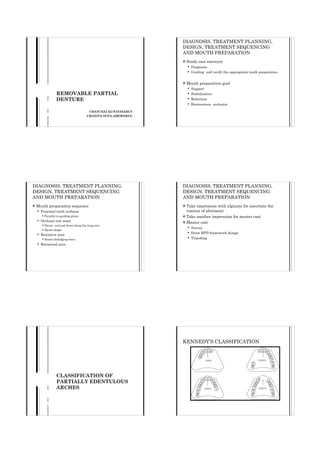
- 1. DIAGNOSIS, TREATMENT PLANNING, DESIGN, TREATMENT SEQUENCING AND MOUTH PREPARATION ! Study cast surveyor ! ! ! Diagnosis Guiding and verify the appropriate tooth preparation Mouth preparation goal Support Stabilization ! Retention ! REMOVABLE PARTIAL DENTURE ! ! Harmonious occlusion CHATCHAI KUNAVISARUT CHANITA SUPA-AMORNKUL DIAGNOSIS, TREATMENT PLANNING, DESIGN, TREATMENT SEQUENCING AND MOUTH PREPARATION ! Mouth preparation sequence ! Proximal tooth surfaces ! Occlusal rest seats ! ! ! Parallel to guiding plane Direct occlusal force along the long axis Spoon shape ! Retentive area ! DIAGNOSIS, TREATMENT PLANNING, DESIGN, TREATMENT SEQUENCING AND MOUTH PREPARATION Take impression with alginate for ascertain the contour of abutment ! Take another impression for master cast ! Master cast ! Survey Draw RPD framework design ! Tripoding ! ! Reciprocal area ! Resist dislodging force KENNEDY’S CLASSIFICATION CLASSIFICATION OF PARTIALLY EDENTULOUS ARCHES
- 2. APPLEGATE’S RULE APPLYING THE KENNEDY CLASSIFICATION COMPONENT OF PARTIAL DENTURE DESIGN MAJOR CONNECTOR Join the components on one side of the arch with those on the other side ! Rigidity " Distribution force ! Not impingement subgingival ! MAJOR CONNECTOR BORDER OF MAJOR CONNECTOR ! Design Symmetrical Cross midline at right angle ! Avoid torus ! Smooth and round contour ! Self cleansing ! !
- 3. PALATAL BAR MAXILLARY MAJOR CONNECTOR Palatal bar Palatal strap ! Anteroposterior palatal bar ! Horseshoe ! Anteroposterior palatal strap ! Complete palate ! ! Narrow half oval with thickest point at the middle Interim application Uncomfortable Little vertical support All support derive from remaining teeth Short span class III Should not place anterior to second molar PALATAL STRAP ANTEROPOSTERIOR PALATAL BAR Anterior bar = Palatal strap Posterior bar = Palatal bar Wide – thin band of metal Join two bar with flat longitudinal element At least 8 mm. wide Rigidity Little interfere tongue Minimized soft tissue coverage Patient accept Uncomfortable Resistance to bending and twisting force Little support from palate Distribute stress Not the first choice Patient may complain of palatal coverage Support is not major consideration Widely separate abutment HORSESHOE CONNECTOR Thin metal band running along the lingual surface of remaining teeth and extending (6-8 mm.) on to the palatal tissue Symmetry Replaced several anterior teeth Prominent median palatal suture line Inoperable torus Tendency to flex or deform Not good for cross arch stabilization More rigid connector cannot be used ANTEROPOSTERIOR PALATAL STRAP Indicated when replace numerous teeth or present of palatine torus Extensive length of border may irritation to tongue Open area in palatal region at least 20x15 mm. Good support from palate Resistance to flexure Uncomfortable
- 4. COMPLETE PALATE Ultimate rigidity and support INDICATION OF MAXILLARY MAJOR CONNECTOR Anterior border cover cingular of anterior teeth Greatest amount of tissue coverage Replaced all posterior teeth Condition Major connector Weak periodontal support of remaining teeth -Wide palatal strap Adequate periodontal support of remaining teeth -Palatal strap Long span distal extension Posterior border extend to hard and soft palate junction -Ant.-post. palatal strap -Complete palate -Ant.-post. palatal bar -Complete palate Replaced anterior teeth Periodontal compromised -Ant.-post. palatal strap -Complete palate -Horseshoe Distribution force to remaining teeth and tissue Stabilization Extensive tissue coverage MANDIBULAR MAJOR CONNECTOR Lingual bar Lingual plate ! Double lingual bar ! Labial bar Condition Major connector ! Torus present -Ant.-post. Palatal strap ! -Ant. -post. Palatal bar -Horseshoe •Very sparing use horseshoe connector •Palatal bar is rarely indicated LINGUAL PLATE LINGUAL BAR Half pear shape and thin piece of metal Indicate for all tooth support unless insufficient space Scallop appearance At least 8 mm. between gin. margin and floor of mouth Always support by rests Minimum contact with teeth and soft tissue Insufficient vertical space for lingual bar Half pear shape Splinting Simplicity Decrease plaque accumulate Need extreme care for design and construction Existing of mandibular tori Exceptional rigidity More comfortable than lingual bar Extensive coverage
- 5. DOUBLE LINGUAL BAR Characteristics of both lingual bar and plate Join 2 bars with rigid minor connector Contact with remaining anterior teeth indicated Marginal gingival receives natural stimulation Horizontal stabilization Tendency to trap debris Not comfortable LABIAL BAR MANDIBULAR MAJOR CONNECTOR Run across the mucosa on facial surface Indicated in the presence of a gross uncorrectable interference Condition Mandibular major connector Tooth support Lingual bar -Insufficient space Lingual plate -Inoperative torus Half pear shape -High lingual frenum attachment Swing-lock -Reduced periodontal support in anterior teeth -Modified lingual plate Tipped remaining mandibular teeth -Large interproximal space -Double lingual bar (step back design) Poor patient acceptance Distort lower lip Discomfort Condition Mandibular major connector Replace all posterior teeth Lingual plate • Labial bar is rarely indicated MINOR CONNECTOR
- 6. MINOR CONNECTOR TYPE OF MINOR CONNECTOR Join the remaining component of RPD to the major connector ! Distribute force to supporting teeth and oral tissues ! Rigidity ! ! JOIN CLASP TO MAJOR CONNECTOR Join clasp to major connector Join direct retainers or auxiliary rest to major connector ! Join denture base to major connector ! Serve as approach arms for bar- type clasp ! JOIN INDIRECT RETAINERS OR AUXILIARY REST TO MAJOR CONNECTOR Right angle with the major connector Rigid Gently curve junction Locate on proximal surface Positioned in lingual embrassure Broad buccolingually but thin mesiodistally JOIN DENTURE BASE TO MAJOR CONNECTOR OPEN CONSTRUCTION FORM LADDER LIKE NETWORK Strong enough to anchor denture base Open construction form ladder like network Mesh construction Bead, wire or nail head components on metal base Distal extension In maxillary arch, extend as far posterior as practical In mandibular arch, extend two thirds the length of edentulous ridge
- 7. SERVE AS APPROACH ARMS FOR BAR- TYPE CLASP Not required to be rigid Must not cross tissue undercut RESTS AND REST SEAT PRIMARY REST ! ! A rest that is part of a retentive clasp is referred to a primary rest ! ! A rest that is responsible for additional support or indirect retention is called an auxiliary rest or secondary rest AUXILIARY REST ! Prevent vertical movement Transmit force to supporting tissue ! Ball and socket joints ! Indirect retainer in extension base Place anterior or posterior to the axis of rotation MAJOR FORM OF REST Occlusal rest Lingual or cingulum rest ! Incisal rest ! !
- 8. OCCLUSAL REST OCCLUSAL REST Floor of rest seat slightly inclined toward the center of the teeth Triangular Deepest portion located near the center 1/3 – 1/2 of mesiodistal diameter At least 0.5 mm. thick at thinnest point Approximate 1/2 of bucco lingual width 1.0-1.5 mm. thick at the marginal ridge LINGUAL AND CINGULUM REST INCISAL REST Primarily used on maxillary canine Frequently used in mandibular canine V shape Small V shaped notch Ball and socket assembly Located approximately 1.5 to 2.0 mm. from the proximal incisal angle DIRECT RETAINER ! ! Engage abutment and resist dislodging forces Two type ! Intracoronal direct retainer ! ! ! DIRECT RETAINER Precision attachment Semiprecision attachment Extracoronal direct retainer ! Retentive clasp ! ! ! Suprabulge Infrabulge Attachment
- 9. RETENTIVE CLASP ASSEMBLIES ! Structure of clasp assembly Rest ! Retentive arm ! Reciprocal element ! Minor connector RETENTION ! The quality of clasp that resists forces acting to dislodge component from supporting tissue ! Depend on ! Type of clasp Flexibility ! Undercut ! ! CLASP ARM FLEXIBILITY ! RECIPROCATION Depend on Length " increase Cross-sectional diameter "circular ! Longitudinal taper ! Clasp curvature " single plane ! Metallurgical properties of alloy "gold , wrought wire ! ! The quality of clasp that counteracts lateral displacement of an abutment when retentive clasp terminate RECIPROCATION ELEMENT ENCIRCLEMENT Cast clasp Lingual plate ! Combination of mesial and distal minor connector ! ! ! ! Prepared parallel to path of insertion The characteristic of clasp that prevent movement of abutment away from associated clasp assembly ! Contact over at least 180°
- 10. LOCATION OF RETENTIVE CLASP TERMINUS PASSIVITY ! Quality of clasp that prevent the transmission of the adverse forces to the associated abutment ! ! Mesial or distal line angle Facial surface better than lingual surface ! ! Length " Flexibility Contraindicated in premolar SIMPLE CIRCLET DESIGN (Aker’s clasp) Widely used REVERSE AKER DESIGN Undercut located adjacent to edentulous area Tooth support RPD Engage undercut remote from edentulous area Half round cross sectional Disadvantages - Increase circumference clinical crown - Increase tooth coverage MULTIPLE CIRCLET DESIGN 2 simple circlet clasp joined at the terminal aspect of their reciprocal elements Principle abutment is periodontal compromised Disadvantage - The same as simple circlet and reverse circlet Infrabulge clasp is contraindicated Kennedy class I ,II Disadvantage - Reduced strength - Lack of rest adjacent to edentulous area - Poor esthetic EMBRASURE CLASP 2 simple circlet joined at bodies Used on no edentulous area side Insufficient tooth preparation results in Inadequate cross sectional dimension Compromised clasp strength
- 11. RING CLASP DESIGN Indicated on tipped mandibular molar Engage mesiolingual or mesiobuccal undercut Auxiliary bracing arm Distal and mesial –occlusal rest Disadvantage - Tooth coverage - Difficult correction Contraindication - Limit vestibular depth - Soft tissue undercut Lingual Buccal C-CLASP DESIGN (Back action clasp) WROUGHT WIRE CIRCUMFERENTIAL CLASP “Fishhook” or “Hairpin” clasp Combination clasp - Occlusal rest - Cast metal reciprocal arm - Wrought wire retentive arm Simple circlet clasp with loop back retentive arm Circular cross sectional Sufficient crown height Kennedy class I and II Disadvantage - Insufficient flexibility - Tooth coverage - Esthetic compromised Mesiobuccal undercut Minimal tooth coverage Disadvantage -Breakage -Minimal stabilizing COMBINATION CLASP IN INFRABULGE CLASP ! ! Bar type Flexibility ! ! ! ! Length Taper More esthetics T-clasp, modified T clasp, Y clasp and I bar
- 12. DESIGN RULES ! Disadvantage ! Food accumulate ! Flexibility ! " Horizontal stability " ! Approach arm ! ! must not impinge soft tissue cross perpendicular to free gingival margin Uniformly tapered " Flexibility Terminate clasp positioned " Apically on the abutment ! Rigid minor connector " Bracing and Stabilization ! ! T-CLASP DESIGN Kennedy class I and II I-CLASP OR I BAR Contact area Undercut locate adjacent edentulous area O.01’’ undercut 2-3 mm. in height 1.5-2 mm. in width Contraindication - Severe soft tissue undercut - High of contour locate near occlusal surface A = Approach arm B= Vertical projection of approach arm C= Location where B cross perpendicular to free gingival D=Point of first tooth contact E=Terminus of the retentive clasp F= Encirclement portion Mesial rest Kennedy class I and II RPI - Mesial rest - Proximal plate - I bar MODIFIED T-CLASP Y-CLASP DESIGN Equivalent to T-clasp No retentive horizontal projection Kennedy class I and II Undercut locate near adjacent edentulous area Canine and premolar Advantage - Improve esthetic compare with conventional T clasp Mesial and distal projection terminate near occlusal surface
- 13. INDIRECT RETAINER INDIRECT RETAINER Framework component that resists rotational displacement of an extension base from the supporting tissue ! Require for Kennedy class I, II and IV ! EFFECT OF ROTATIONAL MOVEMENT ! Occlusal dislodging forces ! ! Denture base move away from supporting tissue Anterior segment of major connector impinge upon underlining tissue
- 14. FACTOR DETERMINE INDIRECT RETAINER FORM OF INDIRECT RETAINER Position on the opposite site of fulcrum line Perpendicular and far from fulcrum line ! Canine and premolar ! Rest at each end of lingual plate Auxiliary occlusal rest Cingulum rest ! Incisal rest ! ! ! ! Distal Extension RPD ! Direct retainer design 81 Indirect retainer 83 84
- 15. SUPPORT FOR DISTAL EXTENSION DENTURE BASE Impression technique Maximum border extension Accurate border detail ! Primary supporting area ! Form of the ridge under function Final impression with custom tray and elastomeric impression material ! Altered-cast technique ! ! ! 86 Miscellaneous “Being excited about being wrong because that means you’ve discovered something new” Retentive arms should be on the same side ! Dimpling ! Treatment denture ! RPD drawing - in paper - on the cast ! THANK YOU 87