1. ED34-862 Specifications
2. Specifications
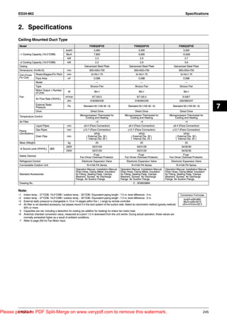
Ceiling Mounted Duct Type
Model FXMQ20PVE FXMQ25PVE FXMQ32PVE
kcal/h 2,000 2,500 3,200
∗1 Cooling Capacity (19.5°CWB) Btu/h 7,800 9,900 12,600
kW 2.3 2.9 3.7
∗2 Cooling Capacity (19.0°CWB) kW 2.2 2.8 3.6
Casing Galvanized Steel Plate Galvanized Steel Plate Galvanized Steel Plate
Dimensions: (H×W×D) mm 300×550×700 300×550×700 300×550×700
Coil (Cross Rows×Stages×Fin Pitch mm 3×16×1.75 3×16×1.75 3×16×1.75
Fin Coil) Face Area m² 0.098 0.098 0.098
Model — — —
Type Sirocco Fan Sirocco Fan Sirocco Fan
Motor Output × Number W 90×1 90×1 90×1
of Units
Fan m³/min 9/7.5/6.5 9/7.5/6.5 9.5/8/7
Air Flow Rate (HH/H/L)
cfm 318/265/230 318/265/230 335/282/247
External Static
Pressure Pa Standard 50 (100-30 ∗3) Standard 50 (100-30 ∗3) Standard 50 (100-30 ∗3)
7
Drive Direct Drive Direct Drive Direct Drive
Temperature Control Microprocessor Thermostat for Microprocessor Thermostat for Microprocessor Thermostat for
Cooling and Heating Cooling and Heating Cooling and Heating
Air Filter ∗4 ∗4 ∗4
Liquid Pipes mm φ6.4 (Flare Connection) φ6.4 (Flare Connection) φ6.4 (Flare Connection)
Gas Pipes mm φ12.7 (Flare Connection) φ12.7 (Flare Connection) φ12.7 (Flare Connection)
Piping
Connections VP25 VP25 VP25
Drain Pipe mm External Dia. 32 External Dia. 32
( Internal Dia. 25 ) ( Internal Dia. 25 ) ( External Dia. 25 )
Internal
Dia. 32
Mass (Weight) kg 25 25 25
220V 33/31/29 33/31/29 34/32/30
∗6 Sound Level (HH/H/L) dBA
240V 33/31/29 33/31/29 34/32/30
Safety Devices Fuse. Fuse. Fuse.
Fan Driver Overload Protector. Fan Driver Overload Protector. Fan Driver Overload Protector.
Refrigerant Control Electronic Expansion Valve Electronic Expansion Valve Electronic Expansion Valve
Connectable Outdoor Unit R-410A PA Series R-410A PA Series R-410A PA Series
Operation Manual. Installation Manual. Operation Manual. Installation Manual. Operation Manual. Installation Manual.
Drain Hose. Clamp Metal. Insulation Drain Hose. Clamp Metal. Insulation Drain Hose. Clamp Metal. Insulation
Standard Accessories for Fitting. Sealing Pads. Clamps. for Fitting. Sealing Pads. Clamps. for Fitting. Sealing Pads. Clamps.
Washers. Screws. Air Discharge Washers. Screws. Air Discharge Washers. Screws. Air Discharge
Flange. Air Suction Flange. Flange. Air Suction Flange. Flange. Air Suction Flange.
Drawing No. C : 3D060388A
Note:
∗1 Indoor temp. : 27°CDB, 19.5°CWB / outdoor temp. : 35°CDB / Equivalent piping length : 7.5 m, level difference : 0 m. Conversion Formulae
∗2 Indoor temp. : 27°CDB, 19.0°CWB / outdoor temp. : 35°CDB / Equivalent piping length : 7.5 m, level difference : 0 m. kcal/h=kW×860
∗3 External static pressure is changeable in 13 or 14 stages within the ( ) range by remote controller. Btu/h=kW×3412
∗4 Air filter is not standard accessory, but please mount it in the duct system of the suction side. Select its colorimetric method (gravity method) cfm=m³/min×35.3
50% or more.
5 Capacities are net, including a deduction for cooling (an addition for heating) for indoor fan motor heat.
∗6 Anechoic chamber conversion value, measured at a point 1.5 m downward from the unit centre. During actual operation, these values are
normally somewhat higher as a result of ambient conditions.
7 Refer to page 255 for Fan Motor Input.
Please purchase PDF Split-Merge on www.verypdf.com to remove this watermark.
FXMQ-P 245
2. Specifications ED34-862
Ceiling Mounted Duct Type
Model FXMQ40PVE FXMQ50PVE FXMQ63PVE FXMQ80PVE
kcal/h 4,000 5,000 6,300 8,000
∗1 Cooling Capacity (19.5°CWB) Btu/h 16,000 19,800 24,900 31,700
kW 4.7 5.8 7.3 9.3
∗2 Cooling Capacity (19.0°CWB) kW 4.5 5.6 7.1 9.0
Casing Galvanized Steel Plate Galvanized Steel Plate Galvanized Steel Plate Galvanized Steel Plate
Dimensions: (H×W×D) mm 300×700×700 300×1,000×700 300×1,000×700 300×1,000×700
Coil (Cross Rows×Stages×Fin Pitch mm 3×16×1.75 3×16×1.75 3×16×1.75 3×16×1.75
Fin Coil) Face Area m² 0.148 0.249 0.249 0.249
Model — — — —
Type Sirocco Fan Sirocco Fan Sirocco Fan Sirocco Fan
Motor Output × Number W 140×1 350×1 350×1 350×1
of Units
Fan m³/min 16/13/11 18/16.5/15 19.5/17.5/16 25/22.5/20
Air Flow Rate (HH/H/L)
cfm 565/459/388 635/582/530 688/618/565 883/794/706
External Static Pa Standard 100 (160-30 ∗3) Standard 100 (200-50 ∗3) Standard 100 (200-50 ∗3) Standard 100 (200-50 ∗3)
Pressure
Drive Direct Drive Direct Drive Direct Drive Direct Drive
Temperature Control Microprocessor Thermostat Microprocessor Thermostat Microprocessor Thermostat Microprocessor Thermostat
for Cooling and Heating for Cooling and Heating for Cooling and Heating for Cooling and Heating
Air Filter ∗4 ∗4 ∗4 ∗4
Liquid Pipes mm φ6.4 (Flare Connection) φ6.4 (Flare Connection) φ9.5 (Flare Connection) φ9.5 (Flare Connection)
Gas Pipes mm φ12.7 (Flare Connection) φ12.7 (Flare Connection) φ15.9 (Flare Connection) φ15.9 (Flare Connection)
Piping
Connections VP25 VP25 VP25 VP25
Drain Pipe mm External Dia. 32 External Dia. 32 External Dia. 32
( Internal Dia. 25 ) ( Internal Dia. 25 ) ( Internal Dia. 25 ) ( External Dia. 25 )
Internal
Dia. 32
Mass (Weight) kg 28 36 36 36
220V 39/37/35 41/39/37 42/40/38 43/41/39
∗6 Sound Level (HH/H/L) dBA
240V 39/37/35 41/39/37 42/40/38 43/41/39
Fuse. Fuse. Fuse. Fuse.
Safety Devices Fan Driver Overload Fan Driver Overload Fan Driver Overload Fan Driver Overload
Protector. Protector. Protector. Protector.
Refrigerant Control Electronic Expansion Valve Electronic Expansion Valve Electronic Expansion Valve Electronic Expansion Valve
Connectable Outdoor Unit R-410A PA Series R-410A PA Series R-410A PA Series R-410A PA Series
Operation Manual. Operation Manual. Operation Manual. Operation Manual.
Installation Manual. Drain Installation Manual. Drain Installation Manual. Drain Installation Manual. Drain
Hose. Clamp Metal. Hose. Clamp Metal. Hose. Clamp Metal. Hose. Clamp Metal.
Standard Accessories Insulation for Fitting. Sealing Insulation for Fitting. Sealing Insulation for Fitting. Sealing Insulation for Fitting. Sealing
Pads. Clamps. Washers. Pads. Clamps. Washers. Pads. Clamps. Washers. Pads. Clamps. Washers.
Screws. Air Discharge Screws. Air Discharge Screws. Air Discharge Screws. Air Discharge
Flange. Air Suction Flange. Flange. Air Suction Flange. Flange. Air Suction Flange. Flange. Air Suction Flange.
Drawing No. C : 3D060388A
Note:
∗1 Indoor temp. : 27°CDB, 19.5°CWB / outdoor temp. : 35°CDB / Equivalent piping length : 7.5 m, level difference : 0 m. Conversion Formulae
∗2 Indoor temp. : 27°CDB, 19.0°CWB / outdoor temp. : 35°CDB / Equivalent piping length : 7.5 m, level difference : 0 m.
kcal/h=kW×860
∗3 External static pressure is changeable in 13 or 14 stages within the ( ) range by remote controller. Btu/h=kW×3412
∗4 Air filter is not standard accessory, but please mount it in the duct system of the suction side. Select its colorimetric method (gravity method) cfm=m³/min×35.3
50% or more.
5 Capacities are net, including a deduction for cooling (an addition for heating) for indoor fan motor heat.
∗6 Anechoic chamber conversion value, measured at a point 1.5 m downward from the unit centre. During actual operation, these values are
normally somewhat higher as a result of ambient conditions.
7 Refer to page 255 for Fan Motor Input.
Please purchase PDF Split-Merge on www.verypdf.com to remove this watermark.
246 FXMQ-P