1. 5.1 UNDERSTANDING REFLECTION OF LIGHT
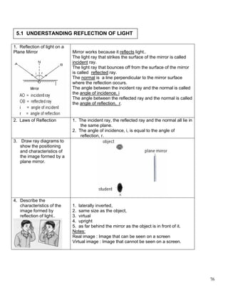
1. Reflection of light on a
Plane Mirror Mirror works because it reflects light..
The light ray that strikes the surface of the mirror is called
incident ray.
The light ray that bounces off from the surface of the mirror
is called reflected ray.
The normal is a line perpendicular to the mirror surface
where the reflection occurs.
The angle between the incident ray and the normal is called
the angle of incidence, i
The angle between the reflected ray and the normal is called
the angle of reflection, r.
2. Laws of Reflection 1. The incident ray, the reflected ray and the normal all lie in
the same plane.
2. The angle of incidence, i, is equal to the angle of
reflection, r.
3. Draw ray diagrams to
show the positioning
and characteristics of
the image formed by a
plane mirror.
4. Describe the
characteristics of the 1. laterally inverted,
image formed by 2. same size as the object,
reflection of light.. 3. virtual
4. upright
5. as far behind the mirror as the object is in front of it.
Notes:
Real image : Image that can be seen on a screen
Virtual image : Image that cannot be seen on a screen.
76
2. Reflection of light on curved mirror
Convex mirror
Concave mirror
Common terminology of curved mirrors
Centre of curvature, The center of sphere of the mirror
C
Principle axis The connecting line from the centre of curvature to point P
Radius of curvature, The distance between the centre of curvature and the surface of
CP the mirror.
Focal point, F The focal point of a concave mirror is the point on the principle axis
where all the reflected rays meet and converge.
The focal point of convex mirror is the point on the principle axis
where all the reflected rays appear to diverge from behind the
mirror.
Focal length, f The distance between the focal point and the surface of the mirror.
(FP or ½ CP)
Object distance, u The distance between the object and the surface of the mirror.
Image distance, v The distance between the image and the surface of the mirror.
Differences
Concave Mirror Convex Mirror
77
3. Rays travelling parallel to the principal axis Rays travelling parallel to the principal axis
converge to a point, called the focal point appear to diverge from a point behind the
on the principal axis. mirror, called the focal point on the principal
FP = focal length, f axis.
FP = focal length, f
Construction Rules for Concave Mirror and Convex Mirror
Rule 1:
Convex Mirror
Concave Mirror
A ray parallel to the principal axis is A ray parallel to the principal axis is reflected
reflected through F. as if it comes from F.
Rule 2:
Concave Mirror Convex Mirror
A ray passing through F is reflected A ray directed towards F is reflected parallel
parallel to the principal axis to the principal axis.
Rule 3:
Concave Mirror Convex Mirror
A ray passing through C is reflected back A ray is directed towards C is reflected back
along the same path through C. along the same path away from C.
78
4. Ray Diagram to determine the position and characteristics of an image in a concave mirror
u > 2f u = 2f or u = c
Characteristics of the image: Characteristics of the image:
f < u < 2f or f < u < c u=f
Characteristics of the image: Characteristics of the image:
u<f
Conclusion
Object Characteristics of the
distrance image:
u > 2f
u = 2f
f < u < 2f
u=f
u<f
Characteristics of the image:
79
5. Ray diagrams for convex mirror
u<f
u < f < 2f
Characteristics of the image:
Characteristics of the image:
Conclusion:
Characteristics of the image of convex
mirror is always virtual, upright and
diminished.
Application of Reflection of Light
1 Anti-parallax Mirror in Ammeters or Voltmeters
A parallax error occurs when the eye sees both the
pointer and its image.
Our eyes are normal to the pointer when the image of
the pointer in the mirror cannot be seen.
80
6. 2. Periscope
A periscope can be used to see over the top of high
obstacles such as a wall.
It is also used inside a submarine to observe the
surrounding above water surface.
Consist of 2 plane mirror inclined at an angle of 45°.
The final image appears upright.
3. Ambulance
Why is the word ‘AMBULANCE’ purposely inverted
laterally on an ambulance car?
Images seen through the rear mirror of a car is
laterally inverted.
4. Make-up Mirror
Concave mirrors with long focal lengths. Produce
virtual, magnified and upright images
5. Transmission of radio waves and
signals
A concave parabolic surface is used to
focus the radio wave signals.
5. Reflector of torchlight
The light bulb is fixed in position at the focal point of
the concave mirror to produce a beam of parallel light
rays. The beam of parallel light rays will maintain a
uniform intensity for a greater distance.
Other applications are the headlight of motor vehicles
and the lamp of slide projectors.
81
7. 7. Widening the field of vision
When a convex mirror is used, the field of vision is
larger than a plane mirror
Convex mirrors are used as rear view mirrors in
motor vehicles to give drivers a wide-angle view of
vehicles behind them.
It is also used as shop security mirrors.
5.2 UNDERSTANDING REFRACTION OF LIGHT
Refraction of light Phenomena where the direction of light is changed when
it crosses the boundary between two materials of
different optical densities.
It due to the change in the velocity of light as it passes
from one medium into another.
82
8. Angle of incidence, i = the angle between the incident
ray and the normal.
Angle of refraction, r = the angle between the refracted
ray and the normal
When i > r, the ray bent towards the normal, and the
speed of light decreases.
When r < i , the ray bent away from the normal and the
speed of light increases.
3 ways in which a ray of light can travel through two medium
When a light ray travels When a ray of light travels When light ray is incident
from less dense medium to from denser medium to less normally on the boundary
denser medium dense medium. between the two medium.
The light ray is refracted The light ray is refracted The light ray is does not
towards the normal. away from the normal. bend.
The speed of light The speed of light
decreases. increases.
The Laws of when light travels from one medium to another medium which has a
Refraction different optical density,
1. the incident ray, the refracted ray and the normal at the point of
incidence all lie in the same plane.
2. the ratio of the sine of the angle of incidence (sin i) to the sine of
Snell’s Law. the angle of refraction (sin r) is a constant.
sin i = constant = n
sin r
Refractive Index, n
The refraction of light is caused by the change in velocity of light when it passes from a
medium to another medium.
n = speed of light in vacuum
speed of light in medium
The refractive index has no units.
It is an indication of the light-bending ability of the medium as the ray of light enters
its surface from the air.
83
9. A material with a higher refractive index has a greater bending effect on light because
it slows light more. It causes a larger angle of deviation of the ray of light, bends the
ray of light more towards the normal.
Examples
1. Calculate the refractive index of 2. The light ray travels from air to medium
medium x. x. Find the:
(a) incident angle
(b) refracted angle
(c) refractive index
3. A light ray travels from glass to air. The refractive
index of glass is 1.54 and the speed of light in air is 3
x 108 ms-1. Calculate
(a) the angle of refraction, θ
(b) the speed of light in glass.
84
10. 4. A light ray is incident normally on a
glass prism which has a refractive
index of 1.50.
(a) complete the ray diagram.
(b) Find the incident angle and the
refractive angle
5. A light ray travels from air
to plastic. What is the
refractive index of the
plastic?
Real Depth and Apparent Dept
Rays of light coming from the real fish, O travels from water (more dense) to air (less
dense)
The rays are refracted away from the normal as they leave the water.
When the light reaches the eye of the person, it appears to come from a virtual fish, I
which is above the real fish O.
Apparent depth, h = distance of the virtual
image, I from the surface of water.
Real depth, H = the actual distance of the
real objects, O from the surface of water.
Refractive index =
n = Real depth
Apparent depth
n = H
h
85
11. (a) Draw a ray diagram from point P
to the eye to show how the legs
appear shorter.
(b) The depth of water is 0.4 m.
Calculate the distance of the
image of the foot at point P from
the surface of the water.
[Refractive index of water = 1.33]
5.2 UNDERSTANDING TOTAL INTERNAL REFLECTION OF LIGHT
1. When light travels from a denser
medium to a less dense, it bends away
from normal.
A small part of the incident ray is
reflected inside the glass.
.
The angle of refraction is larger than
the angle of incidence, r > i
2. When the angle of incidence, i keeps on
increasing, r too increases and the
refracted ray moves further away from
the normal – and thus approaches the
glass – air boundary.
86
12. 3. The refracted ray travels along the
glass-air boundary.
4. This is the limit of the light ray that can
be refracted in air as the angle in air
cannot be any larger than 90°.
5. The angle of incidence in the denser
medium at this limit is called the critical
angle, c.
The critical angle, c, is defined as the angle of incidence in the denser medium when
the angle of refraction in the less dense medium is 90°.
6. If the angle of incidence is increased
further so that it is greater than the
critical angle, the light is not refracted
anymore, but is internally reflected.
7. This phenomenon is called total internal
reflection.
Total internal reflection is the internal reflection of light at the surface in a medium when
the angle of incidence in the denser medium exceeds a critical angle.
The two conditions for total internal reflection to occur are:
1. light ray enters from a denser medium towards a less dense medium
2. the angle of incidence in the denser medium is greater than the critical angle of
the medium.
Relation between Critical Angle and Refractive Index.
87
13. 1. A light rays incident on a plastic block at X.
Which shows the critical angle of plastic?
2. Figure 1 shows a light ray strikes the
surface of a prism. The refractive index
of glass is 1.5. Find the critical angle.
Complete the path of the light ray that
passes into and out of the prism.
3. A light ray passes through an ice block
and emerges from the ice block at Y.
(b) Label the critical angle as c.
(c) Find the value of the critical angle of ice.
Natural Phenomenon involving Total Internal Reflection
1. Mirages
Mirage is caused by refraction and total internal reflection.
Mirage normally occur in the daytime when the weather is hot.
The air above the road surface consists of many layers.
The layers of air nearest the road are hot and the layers get cooler and denser towards
the upper layers.
The refractive index of air depends on its density. The lower or hotter layers have a
lower refractive index than the layers above them.
A ray of light from the sky traveling downwards gets refracted away from the normal.
88
14. As the ray passes through the lower layers, the angle of incidence increases while
entering the next layer.
Finally, the ray of light passes through a layer of air close to the road surface at an
angle of incidence greater then the critical angle.
Total internal reflection occurs at this layer and the ray of light bends in an upward
curve towards the eye of the observer.
The observer sees the image of the sky and the clouds on the surface of the road as a
pool of water.
Rainbow
A rainbow is a colourful natural
phenomenon caused by refraction,
dispersion and total internal reflection of
light within water droplets.
Dispersion : The separation of light into
colours arranged according to their
frequency.
When sunlight shines on millions of water droplets in the air after rain, a multicoloured
arc can be seen.
When white light from the sun enters the raindrops, it is refracted and dispersed into its
various colour components inside the raindrops.
When the dispersed light hits the back of the raindrop, it undergoes total internal
reflection.
It is then refracted again as it leaves the drop.
The colours of a rainbow run from violet along the lower part of the spectrum to red
along the upper part.
Sunset
The Sun is visible above the horizon even though it has set below the horizon.
Light entering the atmosphere is refracted by layers of air of different densities
producing an apparent shift in the position of the Sun.
Applications of Total Internal Reflection
89
15. Prism Periscope
The periscope is built using two right-angled prisms.
The critical angle of the glass prisms is 42°.
Total internal reflection occurs when the light rays
strike the inside face of a 45°angles with an angle of
incidence, I, greater than the critical angle, c,.
The image produced is upright and has the same
size as the object.
Advantage of the prisms periscope compared to a mirror periscope:
(a) the image is brighter because all the light energy is reflected.
(b) the image is clearer because there are no multiple images as formed in a mirror
periscope.
Prism Binoculars
A pair of binoculars uses two prisms which are
arranged as shown in figure.
Light rays will be totally reflected internally two
times in a pair of binoculars.
The benefits of using prisms in binoculars:
(a) an upright image is produced.
(b) The distance between the objective lens and
the eyepiece is reduced. This make the
binoculars shorter as compared to a
telescope which has the same magnifying
power.
90
16. Optical fibers
Fiber optics consists of a tubular rod
which is made from glass and other
transparent material.
The external wall of a fiber optic is less
dense than the internal wall.
When light rays travel from a denser
internal wall to a less dense external
wall at an angle that exceeds the
critical angle, total internal reflection
occurs repeatedly.
This will continue until the light rays
enter the observer’s eye.
Optical fiber is widely used in Advantage of using optical fibres cables
telecommunication cables to transmit over copper cables:
signal through laser. It can transmit (a) they are much thinner and lighter
signal faster and through long distance (b) a large number of signals can be sent
with high fidelity. through them at one time.
Optical fiber is also used in an (c) They transmit signals with very little loss
endoscope for medical emerging. over great distances.
(d) The signals are safe and free of
electrical interference
(e) The can carry data for computer and TV
programmes.
Fish’s Eye View
A fish is able to see an object
above the water surface because
the rays of light from the object are
refracted to the eyes of the fish or
diver.
Due to total internal reflection, part
of the water surface acts as a
perfect mirror, which allows the
fish and diver to see objects in the
water and the objects around
obstacles. A fish sees the outside world inside a 96° cone.
Outside the 96°cone, total internal reflection
occurs and the fish sees light reflected from the
bottom of the pond. The water surface looks like
a mirror reflecting light below the surface.
5.4 UNDERSTANDING LENSES
1. Types of Lenses
Lenses are made of transparent material such as glass or clear plastics. They have two
faces, of which at least one is curved.
91
17. Convex lenses @ converging lenses Concave lenses @ diverging lenses
- thicker at the centre - thinner at the centre
2. Focal Point and Focal Length of a Lens
Convex Lens
@ Converging
Lens
Focal Point @ A point on the principle axis to which incident rays of light traveling
the principal parallel to the axis converge after refraction through a convex lens.
focus, F
Focal Length, f Distance between the focal point, F and the optical centre , C
Concave lens @
Diverging lens
Focal Point @ A point on the principal axis to which incident rays of light traveling
principal focus, F parallel to the axis appear to diverge after refraction through a
concave lens.
Focal Length Distance between the focal point , F and optical centre, C on the
lens.
Note: Power of Lenses
1. The power of a lens is a measure of its ability to converge or to diverge an incident
beam of light.
2. Power of a lens = 1 / f
3. The focal length, f is measured in metre. The unit of power is m-1 or Diopter or D.
4. The power of a lens is 10 D if its focal length is 0.10 m = 10 cm
5. Power for a convex lens is positive. Power for a concave lens is negative.
92
18. A thin lens with a longer
focal length, f has a lower
power
A thick lens with a shorter
focal length, f has a higher
power.
Thin convex lens Thick convex lens Convex lens: A thick lens
has a stronger converging
effect, i.e the incident beam
of light converges nearer to
the lens.
Thin concave lens Thick concave lens
Find the power: (a) convex lens, f = 20 cm, (b) convex lens, f = 5 cm.
Rules for Ray Diagrams
Convex Lens Concave Lens
The ray parallel to the principal axis is The ray parallel to the principal axis is
refracted through the focus point, F. refracted as if it appears coming from focus
point, F which is located at the same side of
the incident ray.
93
19. A ray passing through the focus point is A ray passing the focus point is refracted
refracted parallel to the principal axis. parallel to the principle axis.
A ray passing through the optical centre
A ray passing through the optical centre travels straight on without bending.
travels straight without bending.
The point of intersection of the rays is a The point of intersection of the rays is a
point on the image. point on the image.
Real image: the image is on the side Virtual image: The image is on the same
opposite of the object. side with the object
u = object distance : the distance from the optical centre to the object
v = image distance : the distance from the optical centre to the image.
Characteristics of the image formed:
(a) real image / virtual image
(b) inverted / upright
(c) Magnified (bigger) / diminished (smaller) / same size
virtual image real image
upright image inverted image
bigger smaller
94
20. Images Formed by Convex Lenses
Object Ray Diagram Characteristics of
distance image
u = infinity Image distance: v
=f
Real image
Inverted
smaller
u > 2f Image distance: f
< v < 2f
Real image
Inverted
Small
u = 2f Image distance: v
= 2f
Real
Inverted
Same size
Image is beyond
f < u < 2f 2F (v > 2f)
• Real
• Inverted
• magnified
Image is at infinity
u = f The image:
• virtual
• upright
• magnified
used to produce
95
21. parallel beam of
light
Image is behind
u < f the object, on the
same side of the
lens.
Image
Virtual, upright
magnified.
Concave Lens
Object Ray diagram Characteristic of
distance Image
LENS FORMULA Rules using lens formula
Equation 1 Sign Positive Negative (-
value (+) )
1 = 1 + 1 f = focal length u Real Virtual
f u v u = object distance image image
v = image distance v Real Virtual
Equation 2 image image
f Convex Concave
m = v m = Linear magnification lens lens
96
22. u u = object distance
v = image distance
Equation 3
m = hi m = Linear magnification
ho hI = size of image
hI0 = size of object
m < 1 : diminished, m = 1 : same size , m > 1 :
magnified.
Examples
1. An object is placed in front of a convex lens
with focal length of 10 cm. Find the nature,
position and magnification of the image
formed when the object distance is 15 cm.
2. An object is placed 20 cm from a concave
lens of focal length – 15 cm.
(a) Calculate the image distance.
(b) State the characteristics of the image
formed.
3. A convex lens with focus length of 15 cm
formed an image which is real, inverted and
same size with the object. What is the
object distance from the lens?
4. When an object of height 3.0 cm is placed
20 cm from a concave lens of focal length
30 cm, what is the height of the image
formed?
Simple Microscopes
Application : to magnified the image
Lens : a convex lens
Object distance: less than the focal length of the lens, u < f
Characteristics of image: virtual, upright, magnified
The magnifying power increases if the focal length of the lens is shorter.
97
23. Compound Microscope:
Application: to view very small objects like microorganisms
Uses 2 powerful convex lenses of short focal lengths.
Objective lens:
Eyepiece lens:
Focal length fo for objective lens is shorter than the focal length for eyepiece lens, fe
Object to observed must be placed between F0 and 2F0
Characteristics of 1st image: real, inverted, magnified
The eyepiece lens is used as a magnifying glass to magnify the first image formed by
the objective lens.
The eyepiece lens must be positioned so that the first image is between the lens and
Fe, the focal point of the eyepiece lens.
Characteristics of final image formed by the eyepiece lens: virtual, upright and
magnified.
Normal Adjustment: The distance between the lenses is greater than the sum of their
individual focal length (fo + fe)
Telescope
• Application : view very distant objects like the planets and the stars.
• Made up of two convex lenses :Objective lens and eyepiece lens
• Focal length fo for objective lens is longer than the focal length for eyepiece lens, fe
98
24. • The objective lens converges the parallel rays from a distant object and forms a
real, inverted and diminished image at its focal point.
• The eyepiece lens is used as a magnifying glass to form a virtual, upright and
magnified image.
• At normal adjustment the final image is formed at infinity.
• This is done by adjusting the position of the eyepiece lens so that the first real
image becomes the object at the focal point, Fe of the eyepiece lens.
• Normal adjustment: The distance between the lenses is f0 + fe
99