Conduit Clips and Cable Clamps Guide
•
1 like•948 views

This document provides information on various conduit clips and clamps for supporting electrical conduit. It includes specifications for M-Series and P-Series spring steel conduit clips, combination push-in wall clips, conduit clamps with bolts, flange-mount conduit clips, and hammer-on pipe clips for supporting different sizes of conduit and mounting to various size flanges. Load limits, materials, features, and packaging quantities are provided for each part number.

Recommended
More Related Content
What's hot
What's hot (20)
Viewers also liked
Viewers also liked (20)
Similar to Conduit Clips and Cable Clamps Guide
Similar to Conduit Clips and Cable Clamps Guide (20)
Recently uploaded
Recently uploaded (20)
Conduit Clips and Cable Clamps Guide
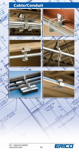
- 1. Cable/Conduit Ph: 1-800-25-CADDY® www.erico.com 53 F519CT10NAEN_BOOK.indb 53F519CT10NAEN_BOOK.indb 53 5/16/11 4:28:06 PM5/16/11 4:28:06 PM
- 2. 54 Ph: 1-800-25-CADDY® www.erico.com Cable/Conduit * M Series 100 lbs. Vertical • 25 lbs. Horizontal (static load) † P Series 25 lbs. Vertical • 15 lbs. Horizontal (ultimate load) Part Number Fig. # Conduit Size (in) Mounting Hole (in) Standard Packaging Quantity 6M* 1 For 14-2 thru 12-3 MC/AC and 3/8 Flexible Conduit 9/32 Plain 100 812M* 1 1/2 to 3/4 9/32 Plain 100 16M* 1 1 9/32 Plain 100 20M* 1 1 1/4 9/32 Plain 100 24M* 1 1 1/2 9/32 Plain 100 32M* 1 2 9/32 Plain 100 812M4I* 1 1/2 to 3/4 1/4-20 Thread Impression 100 6M4I* 1 For 14-2 thru 12-3 MC/AC and 3/8 Flexible Conduit 1/4-20 Thread Impression 100 16M4I* 1 1 1/4-20 Thread Impression 100 20M4I* 1 1 1/4 1/4-20 Thread Impression 100 24M4I* 1 1 1/2 1/4-20 Thread Impression 100 32M4I* 1 2 1/4-20 Thread Impression 100 8P† 2 1/2 9/32 Plain 100 12P† 2 3/4 9/32 Plain 100 16P† 2 1 9/32 Plain 100 8P4I† 2 1/2 1/4-20 Thread Impression 100 12P4I† 2 3/4 1/4-20 Thread Impression 100 16P4I† 2 1 1/4-20 Thread Impression 100 Patent Number: 5,533,696 Fig. #2 Fig. #1 • Spring steel M Clips have finger closure • Spring steel P Clips have push-in installation • Helps to guide alignment with electrical box knockouts. • 9/32” plain hole or 1/4”-20 thread impression options for mounting and field assembly to structure fasteners Features Conduit Clips F519CT10NAEN_BOOK.indb 54F519CT10NAEN_BOOK.indb 54 5/16/11 4:33:02 PM5/16/11 4:33:02 PM
- 3. Ph: 1-800-25-CADDY® www.erico.com 55 Cable/Conduit Part Number Description Standard Packaging Quantity WC812 Combination Push-in Wall Clip 1⁄2” and 3⁄4” EMT conduit 1⁄2” Rigid, IMC, PVC SCH 40 5⁄8” & 3⁄4” Copper Tube MC/AC .700 - .925 OD 100 • Ideal for EMT support between wall studs with SGB/TSGB series brackets • Quickly attaches pipe, conduit, MC/ AC and tube to wall surfaces • Just push in - there’s no need to close the clip • Reduces the need to stock multiple products • Standoff design reduces conduit bending • Helps to guide alignment with electrical box knockouts • Low-profile design minimizes snag potential • Secure with powder-actuated tools, self-tapping concrete anchors or screw guns • Lightweight, one-piece design Features Combination Push-in Wall Clips F519CT10NAEN_BOOK.indb 55F519CT10NAEN_BOOK.indb 55 5/16/11 4:34:01 PM5/16/11 4:34:01 PM
- 4. 56 Ph: 1-800-25-CADDY® www.erico.com Cable/Conduit * Manufactured with retained bolt and built-in nut Part Number Conduit Size - Rigid (in) Conduit Size - EMT (in) Standard Packaging Quantity CD0B* 1/2 1/2 100 CD1B* 3/4 3/4 100 CD2B* 1 1 100 CD2.5B* - 1 1/4 100 CD3B* 1 1/4 1 1/2 100 CD4B* 1 1/2 - 50 CD5B* 2 2 50 CD6B 2 1/2 2 1/2 25 CD7B 3 3 25 CD8B 3 1/2 3 1/2 10 CD9B 4 4 10 Notes: Also available in stainless steel 302. Contact ERICO for price and delivery. To order add suffix SS (ie. CD2B-SS). Stainless do not have nutless feature CD0B through CD5B are UL & cUL Listed and meet or exceed UL Test Requirements See Beam/Purlin chapter for Assemblies (BC200 Series) • Retained bolt and built-in nut means there are less parts to handle or drop. Bright zinc finish • Combo Head bolt ready to work with any tool handy - Slotted, Hex, #3 Phillips and #2 Robertson • Mounting hole size CD0 thru CD3 for 1/4” bolt. CD4 thru CD9 for 5/16” bolt. Available in 3/8” mounting hole for 1/2” - 2” pipe. To order add suffix 37 (i.e. CD2B37) • Can be used in locations where EMT or rigid conduit is used • Accommodates 1/2” thru 4” conduit Features Conduit Clamps with Bolts F519CT10NAEN_BOOK.indb 56F519CT10NAEN_BOOK.indb 56 5/16/11 4:34:29 PM5/16/11 4:34:29 PM
- 5. Ph: 1-800-25-CADDY® www.erico.com 57 Cable/Conduit Fig. #2 * Load Limit: 25 lbs (ultimate load) † Load Limit: 15 lbs (ultimate load) 25# 15# Indicated loads are ultimate and should not be combined Push-In Fig. #1 Part Number Fig. # Description Standard Packaging Quantity 8P24* 1 1/2” conduit to 1/8” to 1/4” flanges 100 8P58* 1 1/2” conduit to 5/16” to 1/2” flanges 100 8P912* 1 1/2” conduit to 9/16” to 3/4” flanges 100 12P24* 1 3/4” conduit to 1/8” to 1/4” flanges 100 12P58* 1 3/4” conduit to 5/16” to 1/2” flanges 100 12P912* 1 3/4” conduit to 9/16” to 3/4” flanges 100 16P24* 1 1” conduit to 1/8” to 1/4” flanges 100 16P58* 1 1” conduit to 5/16” to 1/2” flanges 100 16P912* 1 1” conduit to 9/16” to 3/4” flanges 50 8P24SM† 2 1/2” conduit to 1/8” to 1/4” flanges 100 8P58SM† 2 1/2” conduit to 5/16” to 1/2” flanges 100 8P912SM† 2 1/2” conduit to 9/16” to 3/4” flanges 100 12P24SM† 2 3/4” conduit to 1/8” to 1/4” flanges 100 12P58SM† 2 3/4” conduit to 5/16” to 1/2” flanges 100 12P912SM† 2 3/4” conduit to 9/16” to 3/4” flanges 100 16P24SM† 2 1” conduit to 1/8” to 1/4” flanges 100 16P58SM† 2 1” conduit to 5/16” to 1/2” flanges 100 16P912SM† 2 1” conduit to 9/16” to 3/4” flanges 50 Notes: When using rigid conduit on P series, use next size larger clip (1/2” Rigid use 12P). ‘SM’ suffix designates ‘Sidemount’ application • Requires only a hammer to install • Available for 1/2” thru 1” EMT, rigid, IMT and aluminum conduit • Available with conduit clip bottom mounted or side mounted • Will pivot thru 360° Features Flange-Mount Conduit Clip F519CT10NAEN_BOOK.indb 57F519CT10NAEN_BOOK.indb 57 5/16/11 4:34:51 PM5/16/11 4:34:51 PM
- 6. 58 Ph: 1-800-25-CADDY® www.erico.com Cable/Conduit Fig. #1 Part Number Fig. # Description Standard Packaging Quantity 6M24* 1 3/8” MC/AC cable to 1/8” to 1/4” flanges 100 6M58* 1 3/8” MC/AC cable to 5/16” to 1/2” flanges 100 6M912* 1 3/8” MC/AC cable to 9/16” to 3/4” flanges 100 812M24* 1 1/2” or 3/4” Hammer-On Pipe Clip for Flanges 1/8” to 1/4” 100 812M58* 1 1/2” or 3/4” Hammer-On Pipe Clip for Flanges 5/16” to 1/2” 100 812M912* 1 1/2” or 3/4” Hammer-On Pipe Clip for Flanges 9/16” to 3/4” 100 16M24* 1 1” Hammer-On Pipe Clip for Flanges 1/8” to 1/4” 100 16M58* 1 1” Hammer-On Pipe Clip for Flanges 5/16” to 1/2” 100 16M912* 1 1” Hammer-On Pipe Clip for Flanges 9/16” to 3/4” 100 20M24* 1 1-1/4” Hammer-On Pipe Clip for Flanges 1/8” to 1/4” 100 20M58* 1 1-1/4” Hammer-On Pipe Clip for Flanges 5/16” to 1/2” 100 20M912* 1 1-1/4” Hammer-On Pipe Clip for Flanges 9/16” to 3/4” 50 24M24* 1 1-1/2” Hammer-On Pipe Clip for Flanges 1/8” to 1/4” 50 24M58* 1 1-1/2” Hammer-On Pipe Clip for Flanges 5/16” to 1/2” 50 24M912* 1 1-1/2” Hammer-On Pipe Clip for Flanges 9/16” to 3/4” 50 32M24* 1 2” Hammer-On Pipe Clip for Flanges 1/8” to 1/4” 50 32M58* 1 2” Hammer-On Pipe Clip for Flanges 5/16” to 1/2” 50 32M912* 1 2” Hammer-On Pipe Clip for Flanges 9/16” to 3/4” 50 Snap Close • Available with conduit clip bottom mounted or side mounted • Available for 1/2” thru 1” EMT, rigid and aluminum conduit • Requires only a hammer to install • Will pivot thru 360° Features Flange-Mount Conduit Clip F519CT10NAEN_BOOK.indb 58F519CT10NAEN_BOOK.indb 58 5/16/11 4:35:40 PM5/16/11 4:35:40 PM
- 7. Ph: 1-800-25-CADDY® www.erico.com 59 Cable/Conduit Fig. #2 * Load Limit: 75 lbs (static) † Load Limit: 25 lbs (static) Part Number Fig. # Description Standard Packaging Quantity 6M24SM† 2 3/8” MC/AC cable to 1/8” to 1/4” flanges (Sidemount) 100 6M58SM† 2 3/8” MC/AC cable to 5/16” to 1/2” flanges (Sidemount) 100 6M912SM† 2 3/8” MC/AC cable to 9/16” to 3/4” flanges (Sidemount) 100 812M24SM† 2 1/2” to 3/4” conduit to 1/8” to 1/4” flanges (Sidemount) 100 812M58SM† 2 1/2” to 3/4” conduit to 5/16” to 1/2” flanges (Sidemount) 100 812M912SM† 2 1/2” to 3/4” conduit to 9/16” to 3/4” flanges (Sidemount) 100 16M24SM† 2 1” conduit to 1/8” to 1/4” flanges (Sidemount) 100 16M58SM† 2 1” conduit to 5/16” to 1/2” flanges (Sidemount) 100 16M912SM† 2 1” conduit to 9/16” to 3/4” flanges (Sidemount) 100 20M24SM† 2 11/4” conduit to 1/8” to 1/4” flanges (Sidemount) 100 20M58SM† 2 11/4” conduit to 5/16” to 1/2” flanges (Sidemount) 100 20M912SM† 2 11/4” conduit to 9/16” to 3/4” flanges (Sidemount) 50 24M24SM† 2 11/2” conduit to 1/8” to 1/4” flanges (Sidemount) 50 24M58SM† 2 11/2” conduit to 5/16” to 1/2” flanges (Sidemount) 50 24M912SM† 2 11/2” conduit to 9/16” to 3/4” flanges (Sidemount) 50 32M24SM† 2 2” conduit to 1/8” to 1/4” flanges (Sidemount) 50 32M58SM† 2 2” conduit to 5/16” to 1/2” flanges (Sidemount) 50 32M912SM† 2 2” conduit to 9/16” to 3/4” flanges (Sidemount) 50 F519CT10NAEN_BOOK.indb 59F519CT10NAEN_BOOK.indb 59 5/16/11 4:35:52 PM5/16/11 4:35:52 PM
- 8. 60 Ph: 1-800-25-CADDY® www.erico.com Cable/Conduit CABLE SIZE WIRE SIZES Standard Packing Quantity#12 #10, #9, #8 14-2 (.433-.475 O.D.) KX KX 100 14-3 (.453-.500 O.D.) KX KX 100 12-2(.467-.510 O.D.) KX KX 100 12-3 (.489-.535 O.D.) KX K8 100 From Flange, Wire or Plain Rod Fig. #1 Conduit Hangers CONDUIT SIZE #10 & #12 WIRE #8 & #9 WIRE 3/16” & 1/4” ROD* 1/8”-1/4” FLANGE 5/16”-3/8” FLANGE 7/16”-1/2” FLANGE 1/2” EMT K8 K8 K8 K8 K12 K12 1/2” RIGID K8 K12 K12 K12 K12 K16 3/4” EMT K12 K12 K12 K12 K16 K16 3/4” RIGID K12 K12 K16 K16 K20** K20** 1” EMT — K16 K16 K16 K20** K20** 1” RIGID — — — K20** K20** K20** 1 1/4”EMT — K20 K20 K20 — — **K Series packaged 100 per box. KX - No load rating - positioning only • Supports conduit (EMT, Rigid, ENT, IMT, MC/AC and Aluminum) to rods* or flanges • Can also be used for: flexible metallic tubing, armored cable, portable cables, control tubes, communications cable, etc • No installation tools required Features F519CT10NAEN_BOOK.indb 60F519CT10NAEN_BOOK.indb 60 5/16/11 4:36:17 PM5/16/11 4:36:17 PM
- 9. Ph: 1-800-25-CADDY® www.erico.com 61 Cable/Conduit Fig. #2 The original “Bat Wings” in 1959 Part Number Fig. # Description Standard Packaging Quantity KX 1 Conduit hanger MC/AC or BX to #8 wire 100 K8 2 Conduit hanger 1/2”EMT to 1/4” and smaller rods or flanges 100 K12 2 Conduit hanger 3/4” EMT to 1/4” and smaller rods or flanges 100 K16 2 Conduit hanger 1” EMT to 1/4” and smaller rods or flanges 100 K20 2 Conduit hanger 1-1/4” EMT to 1/4” and smaller rods or flanges 100 Notes: May require dedicated drop wire/rod and EC311 – Consult local authority For horizontal application only when using plain rods. Static Load 25 lbs. Static Load 100 lbs. Static Load 50 lbs. F519CT10NAEN_BOOK.indb 61F519CT10NAEN_BOOK.indb 61 5/16/11 4:36:28 PM5/16/11 4:36:28 PM
- 10. 62 Ph: 1-800-25-CADDY® www.erico.com Cable/Conduit Part Number Fig. # Description Standard Packaging Quantity PCS1 1 Flexible cable support from #8-#12 drop wire for MC/AC 14-2 through 12-3 with ground up to .600 O.D. 100 PCS2 2 Conduit/cable support from #8-#12 drop wire for 1/2” and 3/4” EMT, MC/AC up to .900 O.D. 100 Ultimate Load: 25 lbs. Fig. #2 Fig. #1 Notes: NEC 300.11 requires dedicated drop wire/rod and EC311 • Supports cable and conduit without bending drop wire • Faster installation than traditional methods Features Cable/Conduit From Drop Wire Support F519CT10NAEN_BOOK.indb 62F519CT10NAEN_BOOK.indb 62 5/16/11 4:37:47 PM5/16/11 4:37:47 PM
- 11. Ph: 1-800-25-CADDY® www.erico.com 63 Cable/Conduit Standard Packaging Quantity: 100 Notes: NEC 300.11 requires dedicated drop wire/rod and EC311 When using rigid conduit on P series, use next size larger clip (1/2” Rigid use 12P) 4Z series designates 1/8”-3/8” Flange Size 6Z series designates 3/8”-7/16” Flange Size * When using rigid conduit on P-Series, use next size larger clip (1/2” Rigid use 12P) Part Number Fig. # Description Wire/Rod Size (in) 4Z34 1 Multi-function clip #12 wire - 1/4” 4Z4S 2 Multi-function clip with 1/4-20 stud and hex nut #12 wire - 1/4” 4Z34812M 3 Multi-plus 1/2” or 3/4” conduit #12 wire - 1/4” 4Z3416M 3 Multi-plus 1” conduit #12 wire - 1/4” 4Z348P* 4 Multi-plus 1/2” EMT conduit #12 wire - 1/4” 4Z3412P* 4 Multi-plus 3/4” EMT conduit #12 wire - 1/4” 4Z3416P* 4 Multi-plus 1” EMT conduit #12 wire - 1/4” 6Z34 1 Multi-function clip 3/8” rod 6Z4S 2 Multi-function clip 3/8” rod 6Z34812M 3 Multi-plus 1/2” or 3/4” conduit 3/8” rod 6Z3416M 3 Multi-plus 1” conduit 3/8” rod 6Z348P* 4 Multi-plus 1/2” EMT conduit 3/8” rod 6Z3412P* 4 Multi-plus 3/4” EMT conduit 3/8” rod 6Z3416P* 4 Multi-plus 1” EMT conduit 3/8” rod From Drop Wire, Plain Threaded Rod, or Flange Fig. #4Fig. #3Fig. #2 Fig. #1 • Attaches to #12 wire thru 3/8” rod • Fits 1/8” to 3/8” flanges • Provides attachment of conduit and boxes • Supports #10-24 and 1/4-20 threaded bridle rings • Supports 4” or 4-11/16” electrical box Features Multi-Function Clip F519CT10NAEN_BOOK.indb 63F519CT10NAEN_BOOK.indb 63 5/16/11 4:38:29 PM5/16/11 4:38:29 PM
- 12. 64 Ph: 1-800-25-CADDY® www.erico.com Cable/Conduit Ultimate Load: 25 lbs Part Number Description Conduit Size (in) Standard Packaging Quantity 8P8P 1/2” Conduit to 1/2” conduit 1/2 to 1/2 100 8P12P 1/2” Conduit to 3/4” conduit 1/2 to 3/4 100 8P16P 1/2” Conduit to 1” conduit 1/2 to 1 50 12P12P 3/4”-3/4” Conduit to conduit 3/4 to 3/4 100 12P16P 3/4”-1” Conduit to conduit 3/4 to 1 100 16P16P 1” Conduit to 1” conduit 1 to 1 50 Notes: When using rigid conduit on P series, use next size larger clip (1/2” Rigid use 12P). • Available for conduit 1/2” to 1” EMT and 1/2” to 3/4” Rigid • Ideal as spacer between same or different size conduit • No tools required for installation • Top conduit to be used for support only, not a raceway Features Conduit to Conduit Part Number Description Load Limit (lbs) Standard Packaging Quantity 166M 14-2 thru 12-3 MC/AC to 1” Conduit 100 100 16812M 1/2” or 3/4” Conduit to 1” Conduit 100 100 1616M 1” Conduit to 1” Conduit 100 100 1620M 11/4” Conduit to 1” Conduit 100 50 1624M 11/2” Conduit to 1” Conduit 100 50 1632M 2” Conduit to 1” Conduit 100 50 Notes: Total load of trapeze must not exceed 100 lbs. 1/4-20 Threaded Rod BC Scrap 1” Conduit 16M4I • Fast, easy assembly for lightweight loads up to 100 lbs • Use with 3/8” MC/AC to 2” conduit • No screws or bolts required Features Lightweight Trapeze F519CT10NAEN_BOOK.indb 64F519CT10NAEN_BOOK.indb 64 5/16/11 4:39:15 PM5/16/11 4:39:15 PM
- 13. Ph: 1-800-25-CADDY® www.erico.com 65 Cable/Conduit SCH Series Fig. #3 Fig. #2 Fig. #1 Part Number Fig. # EMT (in) Rigid (in) Cable OD (in) Static Load (lbs) Standard Packaging Quantity SCH8 1 1/2 - - 200 100 SCH12 1 3/4 1/2 - 200 100 SCH16 1 1 3/4 - 200 100 SCH20 1 1 1/4 1 - 200 100 SCH6B 2 3/8 - 0.100 - 0.630 200 100 SCH8B 2 1/2 - 0.340 - 0.710 200 100 SCH12B 2 3/4 1/2 0.570 - 0.920 200 100 SCH16B 2 1 3/4 0.720 - 1.160 200 100 SCH20B 2 1 1/4 1 1.000 - 1.510 200 100 SCH24B 2 1 1/2 1 1/4 1.250 - 1.750 350 50 SCH32B 2 2 1 1/2 1.740 - 2.200 350 50 SCH40B 3 - 2 2.000 - 2.380 350 25 SCH48B 3 2 1/2 2 1/2 2.380 - 2.880 350 25 SCH56B 3 3 3 2.720 - 3.500 350 25 SCH64B 3 3 1/2 3 1/2 3.250 - 4.000 350 10 SCH72B 3 4 4 3.850 - 4.500 350 10 • One-piece installation – no screws or bolts to drop • Installs quickly and easily. Requires only a screwdriver or nut driver for installation • Heavy-duty construction with a bright zinc finish • Size 3/8” MC/AC to 4” EMT conduit • All sizes available with load distribution plate attached to screw • Surface finish: electro zinc plated Features One-Piece Strut Clamp F519CT10NAEN_BOOK.indb 65F519CT10NAEN_BOOK.indb 65 5/16/11 4:41:47 PM5/16/11 4:41:47 PM
- 14. 66 Ph: 1-800-25-CADDY® www.erico.com Cable/Conduit * Aluminum SKs do not have a thread impression. An aluminum nut and bolt are provided. Order with no “A” on end for standard steel bolt and nut. • One-piece construction • Retained bolt and built-in nut prevents dropping of loose parts • One size fits EMT and Rigid • Installs with screwdriver, standard wrench or nut driver • Break in half and install • Bright zinc finish • Works with standard 1 5/8” Strut Features SK Series Fig. #2 Fig. #1 Part Number Fig. # EMT Rigid (in) Standard Packaging Quantity Mild Steel - Static Load 200 lbs SK125I 1 3/4 100 SK165I 1 1 100 SK205I 1 1 1/4 100 SK245I 1 1 1/2 50 SK325I 1 2 50 SK85I 1 1/2 100 Mild Steel - Static Load 350 lbs SK405I 2 2 1/2 50 SK485I 2 3 50 SK565I 2 3 1/2 25 SK645I 2 4 25 Aluminum - Static Load 150 lbs SK12ALA* 1 3/4 100 SK16ALA* 1 1 100 SK20ALA* 1 1 1/4 100 SK24ALA* 1 1 1/2 50 SK32ALA* 1 2 50 SK8ALA* 1 1/2 100 Aluminum - Static Load 200 lbs SK40ALA* 2 2 1/2 50 SK48ALA* 2 3 50 SK56ALA* 2 3 1/2 25 SK64ALA* 2 4 25 Universal One-Piece Strut Clamp F519CT10NAEN_BOOK.indb 66F519CT10NAEN_BOOK.indb 66 5/16/11 4:42:46 PM5/16/11 4:42:46 PM
- 15. Ph: 1-800-25-CADDY® www.erico.com 67 Cable/Conduit Part Number Pipe Size (in) Static Load (lbs) Standard Packaging QuantityNominal O.D. RIGD0050XX 1/2 0.840 400 100 RIGD0075XX 3/4 1.050 400 100 RIGD0100XX 1 1.315 600 100 RIGD0125XX 1 3/4 1.660 600 50 RIGD0150XX 1 1/2 1.900 800 50 RIGD0200XX 2 2 3/8 800 50 RIGD0250XX 2 1/2 2 7/8 800 25 RIGD0300XX 3 3 1/2 800 25 RIGD0350XX 3 1/2 4 1,000 25 RIGD0400XX 4 4 1/2 1,000 25 Notes: XX denotes finish available: EG - Electro-Galvanized, CG - Yellow Chromate, S4 - Stainless 304, S6 - Stainless 316, HD - Hot Dip Galvanized, AL - Aluminum. • Supports rigid pipe to strut • Handles heavy loads • One -piece design incorporates a retained bolt and built-in nut • Installs with either a screwdriver or a nut driver • Complete line is available to fit a wide range of pipe sizes • Available in various materials and finishes Features Rigid Pipe Clamp One-Piece F519CT10NAEN_BOOK.indb 67F519CT10NAEN_BOOK.indb 67 5/16/11 4:44:29 PM5/16/11 4:44:29 PM
- 16. 68 Ph: 1-800-25-CADDY® www.erico.com Cable/Conduit Fig. #1 MC/AC Cable Flexible Conduit Part Number Fig. # Description Standard Packaging Quantity Runs of MC/AC: 1 to 4 MAC2T 1 1 to 4 runs for metal stud 100 Runs of MC/AC: 1 to 2 MAC2 2 Metal or wood stud and up to 1/8” flange 100 MAC2ATA 3 Acoustical Tee 100 MAC2BC 4 1/8” thru 1/2” flange 100 MAC224SM 5 1/8” thru 1/4” flange 100 MAC258SM 5 5/16” thru 1/2” flange 100 MAC2912SM 5 1/16” thru 3/4” flange 100 MAC2VF14 6 1/16” thru 1/4” C purlin or vertical flange 100 MAC2123 7 Z Purlin 100 MAC2AO 8 Offset bracket 100 MAC224 9 1/8” thru 1/4” flange – bottom mount rotates 360° 100 MAC258 9 5/16” thru 1/2” flange – bottom mount rotates 360° 100 MAC2912 9 1/2” thru 3/4” flange – bottom mount rotates 360° 100 MAC24Z34 10 #12 thru 1/4” wire, plain or threaded rod & 1/8” thru 3/8” flange 100 MAC26Z34 10 3/8” plain or threaded rod and 3/8” thru 9/16” flange 100 MAC2FB 11 Through metal stud 100 Notes: Assemblies allow for support from most main and substructures. • Manufactured with stabilizer legs for virtually “wobble-free” support • One fastener for cable size 14-4, 12-4, 12-3, 12-2, 10-3, 10-2 • Snaps into place on metal stud and beam flange up to 1/8” thick. No tools required for installation • MAC2 snaps in half to accommodate single run of cable effectively making two clips from one • Pre-punched holes in clip allow it to be screwed to wood stud, concrete or block • Delivers compliance for: NEC® Article 300.4(d) allowing cable to be positioned a minimum of 11/4” from face of stud. CEC Rule 12-618 for support of MC/AC cable • Factory riveted assemblies are available for installation on flange, purlin, acoustical tee, drop wire, concrete, block or wood and metal stud Features Snap-In Support F519CT10NAEN_BOOK.indb 68F519CT10NAEN_BOOK.indb 68 5/16/11 4:44:57 PM5/16/11 4:44:57 PM
- 17. Ph: 1-800-25-CADDY® www.erico.com 69 Cable/Conduit Fig. #5 Fig. #4Fig. #3Fig. #2 Fig. #6 Fig. #7 Fig. #8 Fig. #9 Fig. #10 Fig. #11 F519CT10NAEN_BOOK.indb 69F519CT10NAEN_BOOK.indb 69 5/16/11 4:45:12 PM5/16/11 4:45:12 PM
- 18. 70 Ph: 1-800-25-CADDY® www.erico.com Cable/Conduit RMX SERIES Fig. #1 Part Number Fig. # Cable Size Description Standard Packaging Quantity RMX 1 14-2 and 12-2 w/ Ground Wire Clip for Non-Metallic Sheathed Cable 100 RMXDH2 2 14-2 and 12-2 w/ Ground Wire Non-Metallic Sheathed Cable to Deck 100 RMXAB 3 14-2 and 12-2 w/ Ground Wire Non-Metallic Sheathed Cable to Angle Bracket 100 RMXAO 4 14-2 and 12-2 w/ Ground Wire Non-Metallic Sheathed Cable to Offset Bracket 100 RMXVF14 5 14-2 and 12-2 w/ Ground Wire Non-Metallic Sheathed Cable to C Purlin 1/16” to 1/4” Thick 100 RMXAF14 6 14-2 and 12-2 w/ Ground Wire Non-Metallic Sheathed Cable to Z Purlin 1/16” to 1/4” Thick 100 RMXBC 7 14-2 and 12-2 w/ Ground Wire Non-Metallic Sheathed Cable to Beam thru 1/2 Flange 100 RMX4Z34 8 14-2 and 12-2 w/ Ground Wire Non-Metallic Sheathed Cable to #12 Wire thru 1/4” Plain Rod or Beam 1/8” thru 3/8” Flange 100 RMX6Z34 8 14-2 and 12-2 w/ Ground Wire Non-Metallic Sheathed Cable 3/8” Plain or Threaded Rod 3/8” thru 7/16” Flange 100 RMXATS 9 14-2 and 12-2 w/ Ground Wire Non-Metallic Sheathed Cable to Acoustical “Tee -Bar” 100 RMX24 10 1/8”-1/4” Thick Flange 14-2 and 12-2 with Ground Wire; Non-Metallic Sheathed Cable to Beam 100 RMX58 10 5/16”-1/2” Thick Flange 14-2 and 12-2 with Ground Wire; Non-Metallic Sheathed Cable to Beam 100 RMX912 10 9/16”-3/4” Thick Flange 14-2 and 12-2 with Ground Wire; Non-Metallic Sheathed Cable to Beam 100 Notes: Not for use in Canada on NMC wire or power application; Assemblies allow support from most main and substructures • Supports non-metallic cable • When used in combination with other CADDY® Fasteners, RMX can be installed on main or substructures, drop wire and acoustical tee Features Non-Metallic Sheathed Cable Clip F519CT10NAEN_BOOK.indb 70F519CT10NAEN_BOOK.indb 70 5/16/11 4:47:22 PM5/16/11 4:47:22 PM
- 19. Ph: 1-800-25-CADDY® www.erico.com 71 Cable/Conduit Assemblies allow support from most main and substructures Fig. #2 Fig. #3 Fig. #4 Fig. #5 Fig. #6 Fig. #7 Fig. #8 Fig. #9 Fig. #10 F519CT10NAEN_BOOK.indb 71F519CT10NAEN_BOOK.indb 71 5/16/11 4:47:33 PM5/16/11 4:47:33 PM
- 20. 72 Ph: 1-800-25-CADDY® www.erico.com Cable/Conduit • One riveted assembly • No conduit bends (beam application) • 66% less Drop Wires (rod/wire application) • Delivers with NEC® & CEC compliance Features B18 Series Combination Box/ Conduit Hangers From Drop Wire/ Rod And Beam Fig. #7Fig. #6Fig. #5 Fig. #4Fig. #3Fig. #2 Fig. #1 F519CT10NAEN_BOOK.indb 72F519CT10NAEN_BOOK.indb 72 5/16/11 4:49:08 PM5/16/11 4:49:08 PM
- 21. Ph: 1-800-25-CADDY® www.erico.com 73 Cable/Conduit Add “CO” at the end of the part number, for factory riveted assembly for multiple conduit clips. Includes mounting plate and center conduit clips pre-riveted (additional conduit clips ordered separately). Notes: NEC 300.11 requires dedicated drop wire/rod and EC311. For single and multiple runs of conduit. cUL® us Listed Box and Conduit Support Part Number Fig. # Description Standard Packaging Quantity B18SBT18 1 Box & Conduit Support - Mounts a 4” square box with multiple conduit mounting plate 25 B18SBT184Z 2 Box & Conduit Support - Mounts electrical box with multiple conduit mounting plate and 4Z34 25 812MB18 3 Mounts 4” sq. boxes with 1/2” & 3/4” conduit from #12 wire thru 1/4” rod 25 812MB186 4 Mounts 4” sq. boxes with 1/2” & 3/4” conduit from #12 wire thru 1/4” rod 25 16MB18 4 Mounts 4” sq. boxes with 1” conduit from #12 wire thru 1/4” rod 25 16MB186 4 Mounts 4” sq. boxes with 1” conduit to 3/8” plain or threaded rod 25 6MB18 4 Mounts 4” sq. boxes with MC, AC cable from #12 wire thru 1/4” flange 25 6MB186 4 Mounts 4” sq. boxes with MC, AC cable 3/8” plain or threaded rod 25 812MB18A 5 1/2” or 3/4” Conduit plain center hole for screw or threaded rod mount 25 16MB18A 5 Mounts 4” sq. boxes with 1” conduit plain center hole for screw or threaded rod mount 25 6MB18A 5 Mounts 4” sq. boxes with MC, AC cable plain center hole for screw or threaded rod mount 25 812MB18S 6 Mounts 4” sq. boxes with 1/2” & 3/4” conduit with 1/4-20 x 9/16” stud in center hole 25 812MB1824 7 Mounts 4” sq. boxes with 1/2” & 3/4” conduit to 1/8” thru 1/4” flange 25 812MB1858 7 Mounts 4” sq. boxes with 1/2” & 3/4” conduit to 5/16” thru 1/2” flange 25 16MB1824 7 Mounts 4” sq. boxes with 1” conduit to 1/8” thru 1/4” flange 25 16MB1858 7 Mounts 4” sq. boxes with 1” conduit to 5/16” thru 1/2” flange 25 6MB1824 7 Mounts 4” sq. boxes with MC, AC cable 1/8” thru 1/4” flange 25 6MB1858 7 Mounts 4” sq. boxes with MC, AC cable 5/16” thru 1/2” flange 25 F519CT10NAEN_BOOK.indb 73F519CT10NAEN_BOOK.indb 73 5/16/11 4:50:11 PM5/16/11 4:50:11 PM
- 22. 74 Ph: 1-800-25-CADDY® www.erico.com Cable/Conduit Fig. #1 Standoff Decking Fasteners Part Number Fig. # Description Standard Packaging Quantity 6MB18CPNAM 1 Mounts 4” sq. boxes with MC/AC cable with CPNAM 25 16MB18CPNAM 1 Mounts 4” sq. boxes with 1” conduit with CPNAM 25 812MB18CPNAM 1 Mounts 4” sq. boxes with 1/2” or 3/4”conduit with CPNAM 25 6MB18TDH 2 Mounts 4” sq. boxes with MC/AC cable with TDH 25 16MB18TDH 2 Mounts 4” sq. boxes with 1” conduit with TDH 25 812MB18TDH 2 Mounts 4” sq. boxes with 1/2” or 3/4”conduit with TDH 25 6MCPNAM 3 Conduit clip for 14-2 thru 12-3 MC/AC, and 3/8 flexible conduit with CPNAM 50 16MCPNAM 3 Conduit clip for 1” conduit with CPNAM 50 20MCPNAM 3 Conduit clip for 1-1/4” conduit with CPNAM 50 24MCPNAM 3 Conduit clip for 1-1/2” conduit with CPNAM 50 812MCPNAM 3 Conduit clip for 1/2” - 3/4” conduit with CPNAM 50 6MTDH 4 Conduit clip for 14-2 thru 12-3 MC/AC, and 3/8 flexible conduit with TDH 50 16MTDH 4 Conduit clip for 1” conduit with TDH 50 20MTDH 4 Conduit clip for 1-1/4” conduit with TDH 50 24MTDH 4 Conduit clip for 1-1/2” conduit with TDH 50 812MTDH 4 Conduit clip for 1/2” - 3/4” conduit with TDH 50 B18SBT18CPNAM 5 Box & Conduit Support - Mounts a 4” sq. box, multiple conduit mounting plate with CPNAM 25 B18SBT18TDH 6 Box & Conduit Support - Mounts a 4” square box with multiple conduit mounting plate 25 CD0BCPNAM 7 1/2” EMT or RIGID Conduit Clamp with retained bolt, built in nut with CPNAM 50 CD1BCPNAM 7 3/4” Pipe Clip with retained bolt, built-in nut with CPNAM 50 CD2BCPNAM 7 1” EMT or RIGID Conduit Clamp with retained bolt, built-in nut with CPNAM 50 CD2.5BCPNAM 7 1-1/4” EMT Conduit Clamp with retained bolt, built-in nut with CPNAM 50 CD0BTDH 8 1/2” EMT or RIGID Conduit Clamp with retained bolt, built in nut with TDH 50 CD1BTDH 8 3/4” Pipe Clip with retained bolt, built-in nut with TDH 50 CD2BTDH 8 1” EMT or RIGID Conduit Clamp with retained bolt, built-in nut with TDH 50 CD2.5BTDH 8 1-1/4” EMT Conduit Clamp with retained bolt, built-in nut with TDH 50 CPNAM 9 Decking Angle Bracket 100 SBT18TDH 10 Multi-Run, Conduit Hanger Plate with TDH 50 TDH 11 3/8” Plain Hole 50 F519CT10NAEN_BOOK.indb 74F519CT10NAEN_BOOK.indb 74 5/16/11 4:50:31 PM5/16/11 4:50:31 PM
- 23. Ph: 1-800-25-CADDY® www.erico.com 75 Cable/Conduit Fig. #11Fig. #10Fig. #9Fig. #8 Fig. #7Fig. #6Fig. #5 Fig. #4Fig. #3Fig. #2 Roof Decking Thickness IN mm Gauge Lbs. kN. 0.025-0.0276 0.63-0.70 24 130 0.60 0.0276-0.0315 0.70-0.80 23 150 0.70 0.0315-0.0394 0.80-1.00 22 180 0.80 0.0394 1.00 19 200 0.90 0.0516 1.20 18 240 1.07 • Meets the requirements of NEC Section 300.4(E) • Supports conduit 1-1/2” (38 mm) under the roof decking to prevent potential damage from nails or screws • Attach to deck using TDH deck hanger or the CPNAM angle bracket • For use with 14-2 thru 12-3 MC/AC, 3/8 flexible conduit and 1/2” to 1-1/2” EMT Features F519CT10NAEN_BOOK.indb 75F519CT10NAEN_BOOK.indb 75 5/16/11 4:51:24 PM5/16/11 4:51:24 PM
- 24. 76 Ph: 1-800-25-CADDY® www.erico.com Cable/Conduit Part Number Cable O.D. (in) Description Standard Packaging Quantity SC2A 0.218 - 0.281 Low voltage, data and MC/AC cable to 1/16” thru 3/16” flange thickness 100 SC2B 0.312 - 0.375 100 SC2C 0.375 - 0.437 100 SC2D 0.468 - 0.562 100 SC2E 0.500 - 0.718 100 SC2F 0.750 - 0.937 100 SC2G 0.968 - 1.250 100 SC4A 0.218 - 0.281 Low voltage, data and MC/AC cable to 3/16” thru 9/32” flange thickness 100 SC4B 0.312 - 0.375 100 SC4C 0.375 - 0.437 100 SC4D 0.468 - 0.562 100 SC4E 0.500 - 0.718 100 SC4F 0.750 - 0.937 100 SC4G 0.968 - 1.250 100 SC8A 0.218 - 0.281 Low voltage, data and MC/AC cable to 5/16” thru 1/2”flange thickness 100 SC8B 0.312 - 0.375 100 SC8C 0.375 - 0.437 100 SC8D 0.468 - 0.562 100 SC8E 0.500 - 0.718 100 SC8F 0.750 - 0.937 100 SC8G 0.968 - 1.250 100 Cable Snap Clip Notes: No load rating - positioning only • Supports cable from 1/16”- 1/2” flange • Works effectively with MC and AC cable dimensions 3/8” - 1 1/4” and low voltage cables from 7/32” and up • Clip “snaps” on flange and cable “snaps” into clip. Features F519CT10NAEN_BOOK.indb 76F519CT10NAEN_BOOK.indb 76 5/16/11 4:53:08 PM5/16/11 4:53:08 PM
- 25. Ph: 1-800-25-CADDY® www.erico.com 77 Cable/Conduit Notes: Ultimate load limit 75 lbs. - WMX6, 50 lbs. - WMX3 • Bundle runs* of MC or AC. (*Refer to local authorities and NEC® Article 310 for derating ampacity when flexible power cables are used) • Can be used with 4H series flange clips, DH2 / TDH deck clips, AO or AB nail brackets, VF14 vertical flange, AF14/122/123 Z purlin Features Part Number Description Runs of MC/AC Ultimate Load (lbs) Standard Packaging Quantity WMX3 Cable hanger - 1 1/8” diameter 3 50 100 WMX6 Cable hanger - 1 3/4” diameter 6 75 100 Flexible Conduit and Cable Hanger Part Number Cable Size Standard Packaging Quantity 449 12-2 (.467-.510 O.D.) 12-3 (.489-.535 O.D.) 14-2 (.433-.475 O.D.) 14-3 (.453-.500 O.D.) 100 • Easily attaches MC or AC to metal stud • No tools required for installation • Provides fast installation Features MC/AC Cable To Metal Stud F519CT10NAEN_BOOK.indb 77F519CT10NAEN_BOOK.indb 77 5/16/11 4:54:04 PM5/16/11 4:54:04 PM
- 26. 78 Ph: 1-800-25-CADDY® www.erico.com Cable/Conduit * Nominal outside diameters from .430 thru .560. 14-3, 14-4, 12-2, 12-4 and 10-2 MC/AC Cable † Nominal outside diameters from .560 thru .690. Standard MC sizes: 10/3, 10/4, *8/2, *8/3. Super Neutral Cable: 12/3, 12/4 and *10/2. Isolated Ground: 12/3, 12/4, 10/2, 10/3, 10/4 and 8/2. Part Number Fig. # Description Standard Packaging Quantity Pre-Riveted Factory Assemblies for MCS50 MCS50* 1 MC/AC cable support spacer for up to 4 runs 50 MCS5024 2 To beams 1/8”-1/4” flange thickness (Hammer-On) 25 MCS504Z 3 To #12 wire thru 1/4” plain or threaded rod 25 MCS5058 2 To beams 5/16”-1/2” flange thickness (Hammer-On) 25 MCS506Z 3 To 3/8” plain or threaded rod 25 MCS50912 2 To beams 9/16”-3/4” flange thickness (Hammer-On) 25 MCS50AF14 4 Z Purlin 25 MCS50BC 5 To beams thru 1/2” flange thickness (Screw-On) 25 MCS50BC200 6 To beams 1/8”-5/8” flange thickness (Screw-On) 25 MCS50VF14 7 C Purlin or Open Bar Joist 25 Pre-Riveted Factory Assemblies for MCS100 MCS100* 8 Support bracket #12/14 AC up to 8 cables 50 MCS10024 2 To beams 1/8”-1/4” flange thickness (Hammer-On) 25 MCS1004Z 3 To #12 wire thru 1/4”plain or threaded rod 25 MCS10058 2 To beams 5/16”-1/2” flange thickness (Hammer-On) 25 MCS1006Z 3 To 3/8” plain or threaded rod 25 MCS100912 2 To beams 9/16”-3/4” flange thickness (Hammer-On) 25 MCS100AF14 4 Z Purlin 25 MCS100BC 5 To beams thru 1/2” flange thickness (Screw-On) 25 MCS100BC200 6 To beams 1/8”-5/8” flange thickness (Screw-On) 25 MCS100VF14 7 C Purlin or Open Bar Joist 25 Pre-Riveted Factory Assemblies for MCS101 MCS101† 9 MC/AC cable† support spacer for up to 7 runs 50 MCS10124 2 To beams 1/8”-1/4” flange thickness (Hammer-On) 25 MCS1014Z 3 To #12 wire thru 1/4” plain or threaded rod 25 MCS10158 2 To beams 5/16”-1/2” flange thickness (Hammer-On) 25 MCS1016Z 3 To 3/8” plain or threaded rod 25 MCS101912 2 To beams 9/16”-3/4” flange thickness (Hammer-On) 25 MCS101AF14 4 Z Purlin 25 MCS101BC 5 To beams thru 1/2” flange thickness (Screw-On) 25 MCS101BC200 6 To beams 1/8”-5/8” flange thickness (Screw-On) 25 MCS101VF14 7 C Purlin or Open Bar Joist 25 Fig. #1 • Neatly isolates, supports and secures MC/AC cables • Properly spaces MC/AC cable to help eliminate bundling and NEC® & CEC derating issues • Results in a “neat and workmanlike” installation • Reduces inventory • Holds up to eight MC/AC cables Features Support Bracket for MC/AC Cable MCS Series F519CT10NAEN_BOOK.indb 78F519CT10NAEN_BOOK.indb 78 5/16/11 4:55:27 PM5/16/11 4:55:27 PM
- 27. Ph: 1-800-25-CADDY® www.erico.com 79 Cable/Conduit Fig. #2 Fig. #3 Fig. #4 Fig. #5 Fig. #6 Fig. #7 Fig. #8 Fig. #9 F519CT10NAEN_BOOK.indb 79F519CT10NAEN_BOOK.indb 79 5/16/11 4:55:39 PM5/16/11 4:55:39 PM
- 28. 80 Ph: 1-800-25-CADDY® www.erico.com Cable/Conduit Part Number Fig. # Description Load Rating Per Tab (lbs) Standard Packaging Quantity SBT18 1 Multi-Run, Conduit Hanger Plate 50 50 SBT1824 2 Hammer-on; underside 1/8”-1/4” flange 25 50 SBT1858 2 Hammer-on; underside 5/16”-1/2” flange 25 50 SBT18912 2 Hammer-on; underside 9/16”-3/4” flange 25 50 SBT1824SM 3 Hammer-on; side mount 1/8”-1/4” flange 50 50 SBT1858SM 3 Hammer-on; side mount 5/16”-1/2” flange 50 50 SBT18912SM 3 Hammer-on; side mount 9/16”-3/4” flange 50 50 SBT184Z34 4 Multi-function clip #12 wire thru 1/4” plain rod 15 50 SBT186Z34 4 Multi-function clip 3/8” plain or threaded rod 15 50 SBT18BC 5 Beam clamp thru 1/2” flange 25 50 SBT18BC200 6 Beam clamp 1/8” to 5/8” flanges 33 50 SBT18 Fig. #1 • Single point structure attachment and easy “snap-in” field assembly of up to three conduit clips • No tools necessary for installation of clips • Helps eliminate conduit bends for 1/2” and 3/4” sizes • Available in a variety of riveted assemblies • Helps eliminate multiple beam clamps or strut assemblies • Helps guide alignment with standard 1/2” electrical box knockouts and mounting holes Features Multiple Conduit Mounting Plate F519CT10NAEN_BOOK.indb 80F519CT10NAEN_BOOK.indb 80 5/16/11 4:58:50 PM5/16/11 4:58:50 PM
- 29. Ph: 1-800-25-CADDY® www.erico.com 81 Cable/Conduit Fig. #4 Fig. #3 Fig. #6 Fig. #5 Fig. #2 F519CT10NAEN_BOOK.indb 81F519CT10NAEN_BOOK.indb 81 5/16/11 5:00:00 PM5/16/11 5:00:00 PM
- 30. 82 Ph: 1-800-25-CADDY® www.erico.com Cable/Conduit Note: 4WN: Not to exceed the load rating of the corresponding fastener Part Number Description Static Load Stud Length Standard Packaging Quantity 4WN 1/4-20 thread impression washer wing nut - - 100 • No tools required for installation Features Washer Wing Nut Beam Clamps Part Number Flange Thickness (in) Rod Size Standard Packaging Quantity 4TI58 5/16 to 1/2 1/4-20 100 6TI24 1/8 to 1/4 3/8-16 100 6TI58 5/16 to 1/2 3/8-16 100 6TI912 9/16 to 3/4 3/8-16 100 Static Load: 200 lbs • Requires only a hammer to install • Used to suspend #8 wire, 1/4”, 3/8” plain rod or 1/4” or 3/8” threaded rod from beam flanges 1/8” to 3/4” thick Features Hammer-On Plain and Threaded Rod Hangers F519CT10NAEN_BOOK.indb 82F519CT10NAEN_BOOK.indb 82 5/16/11 5:04:57 PM5/16/11 5:04:57 PM
- 31. Ph: 1-800-25-CADDY® www.erico.com 83 Cable/Conduit CADDY® PYRAMID ST Series Part Number Fig. # H (in) L1 (in) L2 (in) W (in) Surface Area (in^2) Weight lbs / ea. Static Load (lbs)* RPS360400 1 4 10 12.5 8 94.3 2.95 1000 RPS360401 2 6 10 12.5 8 94.3 4.65 1000 RPS360403 3 4 16 18.5 8 140.8 4.40 1500 RPS360404 4 6 16 18.5 8 140.8 7.05 1500 • Provide fixed-height mounting platform 4” or 6” off the roof surface and 10” or 16” of usable strut length • Static load is up to 1,500 lbs • Hot-dip galvanized finish provides superior corrosion protection Features Fixed Strut Supports A B D P12 * Max. recommended load at 10.6 psi roof loading. Contact project or roofing engineer for maximum allowable load on individual project roof system. Fig. #1 Fig. #2 Fig. #3 Fig. #4 H L1 L2 W F519CT10NAEN_BOOK.indb 83F519CT10NAEN_BOOK.indb 83 5/16/11 5:05:33 PM5/16/11 5:05:33 PM
- 32. 84 Ph: 1-800-25-CADDY® www.erico.com Cable/Conduit CADDY® PYRAMID ST Series Part Number Fig. # H1 (in) Max H2 (in) L1 (in) L2 (in) W (in) Surface Area (in^2) Weight lbs / ea. Static Load (lbs)* RPS360402 1 4.6 12 10 12.5 8 94.3 4.30 1000 RPS360405 2 5.5 17 16 18.5 8 140.8 6.00 1500 • Allow elevation change up to 16” off the roof surface with up to 10” or 16” of usable strut length • Static load is up to 1,500 lbs • Hot-dip galvanized finish provides superior corrosion protection Features Adjustable-Height Strut Supports * Max. recommended load at 10.6 psi roof loading. Contact project or roofing engineer for maximum allowable load on individual project roof system. Fig. #1 Fig. #2 F519CT10NAEN_BOOK.indb 84F519CT10NAEN_BOOK.indb 84 5/16/11 5:07:13 PM5/16/11 5:07:13 PM
- 33. Ph: 1-800-25-CADDY® www.erico.com 85 Cable/Conduit D B A C CADDY® PYRAMID RL Series Part Number Fig. # Nominal Pipe Ø (in) H (in) L (in) W (in) Surface Area (in^2) Weight lbs / ea. Max. Nom. Pipe Size (in)* Ø RPS360406 1 3/4 - 3 5.5 12.5 8 94.3 3.85 3 RPS360408 2 2 - 6 5.5 18.5 8 140.8 5.20 6 • Provides roller capability for up to 6” nominal pipe with 5.5” fixed height • Polymeric rollers will not rust, helping to ensure long-lasting performance and smooth roller action • Hot-dip galvanized finish on steel roller axle, fittings and other hardware provides superior corrosion protection • Supports up to 6” diameter (Nom.) Sch. 40 water-filled steel pipe at maximum spacing of 10’ Features Fixed Roller Supports * Maximum diameter of Sch. 40 water-filled steel pipe at maximum 10’ support spacing. Fig. #1 Fig. #2 Ø L H W F519CT10NAEN_BOOK.indb 85F519CT10NAEN_BOOK.indb 85 5/16/11 5:08:00 PM5/16/11 5:08:00 PM
- 34. 86 Ph: 1-800-25-CADDY® www.erico.com Cable/Conduit CADDY® PYRAMID RL Series Part Number Fig. # Nom. Pipe Ø (in) H1 (in) Max. H2 (in) L (in) W (in) Surface Area (in^2) Weight lbs / ea. Max. Nom. Pipe Size (in)* Ø RPS360407 1 3/4 - 3 5.5 12 12.5 8 94.3 4.20 3 RPS360409 2 2 - 6 5.5 16 18.5 8 140.8 5.95 6 • Can accommodate elevation changes of up to 16” off the roof with up to 6” diameter (Nom.) pipe • Polymeric rollers will not rust, helping to ensure long-lasting performance and smooth roller action • Hot-dip galvanized finish on steel roller axle, fittings and other hardware provides superior corrosion protection • Supports up to 6” diameter (Nom.) Sch. 40 water-filled steel pipe at maximum spacing of 10’ Features Adjustable-Height Roller Supports * Maximum diameter of Sch. 40 water-filled steel pipe at maximum 10’ support spacing. Fig. #1 Fig. #2 F519CT10NAEN_BOOK.indb 86F519CT10NAEN_BOOK.indb 86 5/16/11 5:09:20 PM5/16/11 5:09:20 PM
- 35. Ph: 1-800-25-CADDY® www.erico.com 87 Cable/Conduit W H L W H L W H L CADDY® PYRAMID EZ Series • Quick and easy: No tools or fasteners needed; fast snap-on installation • Roof friendly: Made of UV-stabilized EPDM material • Height adjustable: Multiple models allow for height adjustment from 1-3/4” to 4”, 4” to 6”, or 5” to 7” • Convenient: Models can accommodate all pipe and conduit types up to 2” Sch. 40 Features Adjustable-Height Tool-Free Rooftop Pipe Supports Part Number Fig. # Max. Nom. Pipe or Conduit Size (in)* Max. Pipe or Conduit OD (in) H (in) L (in) W (in) Weight lbs / ea. Ultimate Load (lbs)** RPSE1H24 1 1 1.315 1 3/4 - 4 4 6 2 170 RPSE1H57 2 1 1.315 5 - 7 4 6 3.04 170 RPSE2H46 3 2 2.370 4 - 6 4 6 3.30 250 RPSE4H46 – 4 4.500 4 - 6 4 9.5 5.14 400 * Maximum diameter of Sch. 40 water-filled steel pipe at maximum 10’ support spacing. ** Ultimate load at 1/4” deflection. Contact project or roofing engineer for maximum allowable load on individual project roof system. Fig. #1 Fig. #2 Fig. #3 F519CT10 Cable_Conduit_1a.indd 87F519CT10 Cable_Conduit_1a.indd 87 5/26/11 8:51:30 AM5/26/11 8:51:30 AM
- 36. 88 Ph: 1-800-25-CADDY® www.erico.com Cable/Conduit Fig. #2 Fig. #1 Part Number Fig. # Description Standard Packaging Quantity RPS360410 1 Rubber mat for CADDY® PYRAMID ST and RL Series, 9” X 13.5” 10 RPS360411 1 Rubber mat for CADDY® PYRAMID ST and RL Series, 9” X 19.5” 10 RPS360412 2 Retainer strap for CADDY® PYRAMID RL Series, up to 3” 25 RPS360413 3 Retainer strap for CADDY® PYRAMID RL Series, 3.5” - 6” 25 RPSCSEG 4 CADDY® PYRAMID Column Support, EG 1 P110000EG 5 Post Base for A Channel 5 P110000HD 5 Strut Post Base P11 25 CADDY® PYRAMID ST & RL Series Accessories F519CT10NAEN_BOOK.indb 88F519CT10NAEN_BOOK.indb 88 5/16/11 5:12:47 PM5/16/11 5:12:47 PM
- 37. Ph: 1-800-25-CADDY® www.erico.com 89 Cable/Conduit Fig. #5 Fig. #4 Fig. #3 F519CT10NAEN_BOOK.indb 89F519CT10NAEN_BOOK.indb 89 5/16/11 5:13:33 PM5/16/11 5:13:33 PM
- 38. 90 Ph: 1-800-25-CADDY® www.erico.com Cable/Conduit • Supports up to 25 lb static loads • Lightweight, all-plastic construction weighs less than 0,15 kg • Has a small – 4” x 5” footprint • UV-resistant, designed and tested for outdoor use • Handles up to three 1/2” (21,3 mm) or two 3/4” (26,9 mm) or one 1” (33,7 mm) pipes/conduit • No tools or fasteners needed for installation • Helps protect the roof membrane Features Pipe & Equipment Supports Part Number Max. Static Load (lbs) Height (in) PPRPS25H4 25 3 5/8 PPRPS25H6 25 5 5/8 CADDY® PYRAMID 25 • Supports up to 50 lb static loads • Polyethylene closed-cell foam and 1,5 mm steel construction. • The 4” high model has a 10-3/8” x 4” footprint • The 6” high model has a 10-3/8” x 4-3/4” footprint • Electro-galvanized (EG) finish on the rooftop version and grey polyester coating on the plenum version provide superior corrosion protection • Metal top designed to shed water and minimize water collection on foam base • Helps protect the roof membrane Features Part Number Max. Static Load (lbs) Height (in) Surface Finish RPS50AHSV 50 2 1/4 Polyester RPS50H4EG 50 4 EG RPS50H6EG 50 6 EG Pipe & Equipment Supports CADDY® PYRAMID 50 F519CT10NAEN_BOOK.indb 90F519CT10NAEN_BOOK.indb 90 5/16/11 5:14:30 PM5/16/11 5:14:30 PM
- 39. Ph: 1-800-25-CADDY® www.erico.com 91 Cable/Conduit Pipe & Equipment Supports • Supports up to 150 lb static loads • Has six 3/8”-16 threaded inserts with captive nuts that allows the product to be used with standard pipe clamps and accessories • Large 16” x 12” footprint distributes load more evenly than alternative methods • Polyethylene closed-cell foam and 14-gauge steel construction • Electro-galvanized (EG) finish on top plate for added corrosion protection • Helps protect the roof membrane Features Part Number Max. Static Load (lbs) Height (in) Thread Size Surface Finish With Strut RPS150T1 150 3 3/16 3/8-16 EG No RPS150T2 150 4 3/8-16 EG Yes CADDY® PYRAMID 150 Part Number Max. Static Load (lbs) Height (in) Thread Size Surface Finish With Strut RPS300T1 300 3 3/16 3/8-16 EG No RPS300T2 300 4 3/8-16 EG Yes • Dramatically reduces installation time by replacing labor-intensive methods for supporting pipes and conduits • Supports multiple runs of pipe and conduit on roofs and below raised floors • Supports concentrated static loads up to 300 lbs • Absorbs shock and vibration • Protects roof membrane • Metal cover protects from weather and other environmental conditions • Features an electro-galvanized finish for corrosion protection Features Pipe & Equipment Supports CADDY® PYRAMID 300 F519CT10NAEN_BOOK.indb 91F519CT10NAEN_BOOK.indb 91 5/16/11 5:14:49 PM5/16/11 5:14:49 PM
- 40. 92 Ph: 1-800-25-CADDY® www.erico.com Cable/Conduit Pipe & Equipment Supports • Consists of two CADDY® PYRAMID 300 bases tied together with a length of strut • Footprint is 32” x 12” (24” x 16” optional with cutting of strut) for more even load distribution • Supports up to 600 lb static loads • Helps to protect the roof membrane Features Part Number Max. Static Load (lbs) Height (in) Thread Size Surface Finish With Strut RPS600T2 600 4 3/8-16 EG Yes CADDY® PYRAMID 600 F519CT10NAEN_BOOK.indb 92F519CT10NAEN_BOOK.indb 92 5/16/11 5:15:11 PM5/16/11 5:15:11 PM
- 41. Ph: 1-800-25-CADDY® www.erico.com 93 Cable/Conduit Part Number Fig. # Description Static Load lbs Standard Packaging Quantity RPS360420 1 RPS H-Frame Kit, 12x12 in, Foam, Hardware Kit Included 1500 1 RPS360421 1 RPS H-Frame Kit, 12x12 in, Rubber, Hardware Kit Included 1500 1 RPS360422 2 RPS Post Base, 12x12 in, Foam 750 1 RPS360423 2 RPS Post Base, 12x12 in, Rubber 750 1 • Designed to offer superior protection to rooftop membrane • Highly engineered design of the base uniformly distributes load • Continuous bottom surface mitigates unwanted stress concentrations • Ideal for pipework, duct, conduit, cable tray, or any combination of these • Base is made from recycled, UV stabilized engineered thermoplastic • Integral foam pad provides gentle interface for all roof types • Accepts standard strut channels, 1-5/8” x 1-5/8” • Mounting hardware pre-installed in bases • Hot-dip galvanized hardware • Hardware kit includes 6 bolts, 6 strut nuts, and 2 L-brackets to complete H-frame Features CADDY® PYRAMID RPS H-Frame Series 4.6” 12-3/8”12-3/8” 12-3/8”12-3/8”4.6” Fig. #2Fig. #1 NOTES: Maximum static load represents 750 lbs (3,335 N) per foot. The end user must select and evaluate the strut framing to ensure the assembled H-Frame can properly support the applied load. F519CT10NAEN_BOOK.indb 93F519CT10NAEN_BOOK.indb 93 5/16/11 5:15:30 PM5/16/11 5:15:30 PM
- 42. 94 Ph: 1-800-25-CADDY® www.erico.com Cable/Conduit 94 Ph: 1-800-25-CADDY® www.erico.com Part Number Description Standard Packaging Quantity AOL8P Support bracket for 1/2” EMT 100 AOL12P Support bracket for 3/4” EMT or 1/2” Rigid 100 AOL16P Support bracket for 1” EMT or 3/4” Rigid 100 Notes: No Load Rating - Positioning Only • Provides spacing between conduit and deck surface • Easily attached with screw gun or power tool • Permits conduit to be laid out and then attached • Eliminates offset bending conduit Features Metal Deck Conduit Support Part Number Description Standard Packaging Quantity CNB812M Nail Bracket, M-Series 1/2” & 3/4” Conduit 100 CNB8P Nail Bracket, P-Series for 1/2” EMT 100 CNB12P Nail Bracket, P-Series for 3/4” EMT or 1/2” Rigid 100 Notes: No Load Rating - Positioning Only • Used to attach conduit to wood, steel or concrete • Eliminates the need for offset bends • Works with power tools, screw guns or nails • May be attached after positioning conduit Features Nail Bracket F519CT10NAEN_BOOK.indb 94F519CT10NAEN_BOOK.indb 94 5/16/11 5:16:58 PM5/16/11 5:16:58 PM