UWR Weapon Racks Installation Instructions
•
1 like•1,283 views

UWR Weapon Racks Installation Instructions, Southwest Solutions Group, www.southwestsolutions.com, 1-800-803-1083

Recommended
More Related Content
Similar to UWR Weapon Racks Installation Instructions
Similar to UWR Weapon Racks Installation Instructions (20)
More from Installation Manuals - Southwest Solutions Group
More from Installation Manuals - Southwest Solutions Group (6)
Recently uploaded
Recently uploaded (20)
UWR Weapon Racks Installation Instructions
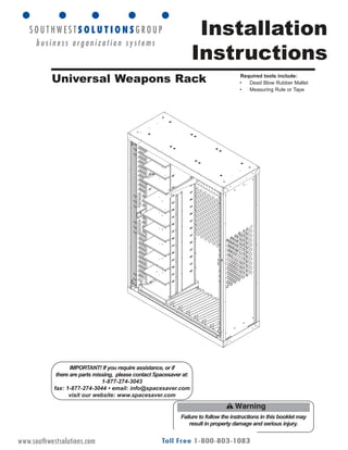
- 1. Installation Instructions Failure to follow the instructions in this booklet may result in property damage and serious injury. IMPORTANT! If you require assistance, or if there are parts missing, please contact Spacesaver at: 1-877-274-3043 fax: 1-877-274-3044 • email: info@spacesaver.com visit our website: www.spacesaver.com Universal Weapons Rack Required tools include: • Dead Blow Rubber Mallet • Measuring Rule or Tape OP-0312 Rev 03_11www.southwestsolutions.com
- 2. 1 Table of Contents Safety and Pre-Installation 2 Sample Cabinet Configurations 2 Assembly 3-7 Operation 7 Parts List 8 Optional Accessories 10 Cart Assembly– UWRCART 10 Handle Assembly - UWR4HK 10 Overstorage Cabinets 11 Cabinet Mounting 11 Assembly-UWRBINFL10 12 Assembly- UWRBIN23OS18 & UWRBIN13OS18 13 UWRCXXXXBP - Back Panels 14/15 Programmed Configurations UWRM2T 16 UWRM16T (M4) 17 UWRM16T (M16) 18 UWRM240BT 19 UWRM240HT 20 UWRM249T 21 UWRMK19T 22 High Density Configuration UWR12M16R26 23 UWR12M16R34 24 UWR12M16R112 25 UWR12M16R112 26 UWR15M16R35 27 UWR15MK16R35 28 84” Configuration Kit UWR8410 29 UWR841226 30 UWR841234 31 UWR841535 32 OP-0312 Rev 03_11 www.southwestsolutions.com
- 3. 2 Safety and Pre-Installation Sample Bin Configurations Standard Height Cabinets (45") 1/3 wide Vertical Bin Storage configuration occupies 1/3 of the cabinet from left to right. Tall Cabinets (61") Lower Vertical Bin Storage configurations are the same as above. Upper Horizontal bins are added to fill the space gained by the taller cabinet and may be configured with 1/3, 2/3 or full width shelves. Before you begin installation: 1. Read through the assembly procedure before starting the project. 2. Understand all safety statements. 3. Use the Sample Bin Configurations below to plan your weapon layout and determine height and mounting location of the cabinet components. 3. Make sure your system will fit within the desired location. 4. Plan to assemble the system where it will be used. Make sure location is clean and flat. 5. Have the necessary tools for assembling the unit. 6. Use of safety glasses and gloves is recommended. (Certain parts may have sharp edges.) • The weapon storage system should only be affixed to a flat surface. • Assembled units must rest on flat surface for proper stability. • Never climb on the system. The system is not designed or intended to be used as a climbing surface. • Distribute weight evenly. • Do not overload the system. Each shelf has an evenly distributed 50 lb. per linear ft. maximum capacity limit. • Items that are unstable, that may roll, slide or cause personal injury, should be stored in a manner that will remain secure during operation. • Each unit is designed for loads within the framework of the unit itself. 2/3 wide Vertical Bin Storage configuration occupies 2/3 of the cabinet from left to right. May have two sets of single shelves or 2/3 wide shelves minus the center panels. Full width Vertical Bin Storage configuration occupies full width of the cabinet. May have three sets of single shelves or full width shelves minus the center panels. NOTE: Overstorage Cabinet adds 18" to cabinet height. Cart Assembly adds 6.8" to cabinet height. OP-0312 Rev 03_11www.southwestsolutions.com
- 4. Assembly 3 Multiple Cabinets Cabinets may be ganged together or stacked and secured with hardware (included), and placed on high-density mobile systems. Use appropriate hardware, in each corner, per local codes when mounting to mobile systems. Levelers Levelers if needed for unlevel surface, should be installed prior to assembly. If levelers are not used, cabinet should be placed on level surface. The levelers screw into holes located on the bottom of the cabinet at each corner. Leveler P/N 960210.001 OP-0312 Rev 03_11 For mounting to Mobile, anchor in four corners, between the outside frame and locker end panel. www.southwestsolutions.com
- 5. Assembly 4 Base Insert bottom hooks on base into front slot in cabinet and drop back in place. Universal Base Insert bottom hooks on base into front slot in cabinet and drop back in place. Universal base must be mounted to the cabinet into the holes at rear of base with tek screws (included). 1 2 3 4 5 6 7 8 9 10 11 12 13 14 15 16 17 18 19 20 21 22 23 24 25 26 27 28 Stock Cups The stock cups are placed into the universal base by inserting the carriage bolt head through the round portion of the key-hole slot. The stock cup may then slide into the slot. Once in the correct postion, turn the wing nut to secure in place. Two stock cups (one in front and one in back) are required for each weapon for transport. See below for cup placement examples. NOTE: Special stock cups for large/heavy weapons also exist. For these weapons 1 or 2 stock cups may be used depending upon the weapon type. See parts list for examples. Stock Cup Placement Guide For even placement of stock cups using standard weapon stocks, use the following slot locations: 10 weapons: Use slots 1, 4, 7, 10, 13, 16, 19, 22, 25 and 28 9 weapons: Use slots 2, 5, 8, 11, 14, 17, 20, 23 and 26 8 weapons: Use slots 1, 5, 9, 13, 17, 21, 25 and 28 7 weapons: Use slots 2, 6, 10, 14, 18, 22 and 26 6 weapons: Use slots 2, 7, 12, 17, 22 and 27 (ie. M60s) or 1,6,11,18, 21 and 26 (ie. M249s) NOTE: These are guidelines for standard weapons without gear/optics attached. Weapons with optics attached, side charging handles, non-standard stocks, spade grips, etc., may require an adjustment in spacing. OP-0312 Rev 03_11www.southwestsolutions.com
- 6. Assembly 5 Pins 61" Unit: Top of rail mut be 14" from inside top of unit Barrel Rest(s) NOTE: The number of barrel rests installed and location on support rail will vary depending on type of weapons to be stored. 1. Barrel rests are equipped with tabs that engage slots on the support rail. 2. Place barrel rest in the desired location and drive tab into slot using soft face dead hammer. If installing Bin Storage system, be sure to leave room for installation. (secure barrel) Support Rail NOTE: The number of support rails installed and position will vary depending on cabinet height and type of weapons to be stored. If installing Horizontal Bin Storage shelves in 61" unit, the top rail should be 14" from the underside of the top of cabinet to the top of the rail. 1. Install the topmost support rail into the cabinet. The support rail pins must engage the keyhole slots located at the rear of the cabinet on the corner posts. Use a soft dead blow hammer to drive pins into place. 2. Repeat for any other support rails. Space additional rails accordingly. NOTE: When used for transport, the heavy duty support rail is required. NOTE: Barrel rest may be fastened in to the support rail with self-tapping screws (supplied) if desired. It is recommended to use a power tool when installing the self-tapping screws. Secure Barrel Support (Transportability) 1. Barrel Supports have 1 1/2” long slots that line up with the holes on the support rail (not the square slots). 2. Place barrel support in the desired location and fasten onto support rail with self-tapping screws (supplied). Do not tighten until adjusted for weapon height. It is recommended to use a power tool when installing the self-tapping screws. 3. Align the top (cap) of the barrel support with the top of the weapon barrel. Tighten the screws. Receiver Mounts (Transportability) 1. Receiver Mounts have 1 1/2” long slots that line up with the holes on the support rail (not the square slots). 2. Place receiver mount in the desired location and fasten onto support rail with self-tapping screws (supplied). Do not tighten until adjusted for weapon height. It is recommended to use a power tool when installing the self-tapping screws. OP-0312 Rev 03_11www.southwestsolutions.com
- 7. Assembly 6 4. Install the vertical walls so the reinforcement rail faces away from the shelves. Top of vertical wall has holes for engaging pins located on underside of top shelf (61" unit) or underside of cabinet top (45" unit). Bottom of vertical wall has slots for engaging tabs located on top of base. Engage the top of the vertical wall first, then slide the bottom into the tabs. 5. Install middle shelves to vertical walls. Middle shelves have tabs on the side to engage vertical wall slots. Bin Storage NOTE: To install Vertical Bin Storage unit in 61" cabinet, the Horizontal Bin unit is required (see page 6). 1. Install the vertical bin base to the bottom of the cabinet. 2. The front of the base locks under the front lip of the cabinet. The rear of the base rests on the rear floor of the cabinet. NOTE: If the cabinet will also house weapons, the butt plate will be factory installed. LEFT SIDE RIGHT SIDE Reinforcement Panel faces away from shelves Holes on vertical wall engage pins on underside of top shelf (61" unit) or underside of cabinet top (45" unit). Slots engage tabs on base FRONT OF CABINET OP-0312 Rev 03_11 3. 61" units: Install the top shelf to the support rail. The tabs at the rear of the shelf engage the square slots in the support rail. 45" units: These units do not use a support rail. The vertical walls align over pins in the underside of the cabinet top. www.southwestsolutions.com
- 8. Assembly 7 LEFT SIDE RIGHT SIDE Reinforcement Panel faces away from shelves Slots engage tabs on base FRONT OF CABINET Top shelf snaps into support rail Extended Bin Side Panels for Tall Cabinets Extended bin side panels and additional shelves for tall cabinets install just like side panels and shelves installed in the previous step. Operation Lockable Sliding Doors The unit is equipped with folding bifold mesh doors and bars that can be locked for security. The doors fold to the side and then slide into the cabinet for easy access. OP-0312 Rev 03_11www.southwestsolutions.com
- 9. 8 Cabinet 45” P/N UWRC4245 (H) 61” P/N UWRC4261 (H) 18” P/N UWRCOS18 (H) 34” P/N UWRCOS34 (H) The “H” denotes handles (factory installed) P/N UWRB2 P/N UWRB5 P/N UWRB4 P/N UWRB6 P/N UWRB10 P/N UWRB7 P/N UWRB8 P/N UWRBU P/N UWRBSC Bases P/N UWRSEBM2 P/N UWRBEWB P/N UWRSSB P/N UWRSWB P/N UWRSP Barrel Supports Horizontal Bin Wall P/N UWRBINHW Vertical Base P/N UWRBINVBS Vertical Bin Wall P/N UWRBINVW Leveler P/N 960210.001 Bolt 5/16-18 X 7/8 P/N 95028.02 Self-tapping Screw 1/4-20 x 1/2" P/N 950086.001 Bolt 1/4-20 X 7/8 P/N 95027.02 Keps Nut 1/4-20 X 7/8 P/N 93015.02 Hardware Rivet (for handle install) .188 x .126 - .250 grip P/N 88013.01 Shelves P/N UWRBINSFL P/N UWRBINS23 P/N UWRBINS13 Support Rail P/N UWRSR42 P/N UWRCART P/N UWR4HK Handle Kit (Set of 4) 1/3 width P/N UWRBINHBS13 2/3 width P/N UWRBINHBS23 Full width P/N UWRBINHBSFL Horizontal Bases OP-0312 Rev 03_11 Parts List P/N UWRCART P/N UWR4HK Handle Kit (Set of 4) www.southwestsolutions.com
- 10. P/N UWRCART 9 Cabinet 45” P/N UWRC4245 (H) 61” P/N UWRC4261 (H) 18” P/N UWRCOS18 (H) 34” P/N UWRCOS34 (H) The “H” denotes handles (factory installed) P/N UWRBU P/N UWRBSC B P/N UWRSTS P/N UWRSTL P/N UWR4HK Handle Kit (Set of 4) Base & Stock Cups Barrel Supports Receiver Mounts P/N UWRBM2SC P/N UWRBM2BRLCP P/N UWRBM240BSC P/N UWRBMK19SC P/N UWRSMRM2 P/N UWRSMRM240B P/N UWRSMRMK19 P/N UWRSM2SPBRL P/N UWRSMK19MZL Support Rail P/N UWRSR42 Support Rail P/N UWRSRHD42 OP-0312 Rev 03_11 Parts List (Transport) P/N UWRCART P/N UWR4HK Handle Kit (Set of 4) www.southwestsolutions.com
- 11. 10 Optional Accessories Cart Assembly–UWRCART (Optional Accessory) Cart Assembly adds 6.8" to cabinet height. (shown mounted on 61" Universal Weapons Rack) 1. Attach the castors to the cart using 5/16-.3/4" serrated flange bolts supplied (qty. 16, 4 per castor). 2. Attach the cabinet to the cart using 5/16-7/8" serrated flange bolts supplied (qty. 4). NOTE: Do not use the 7/8" bolts to attach castors to cart. Bolts are too long and will interfere with cabinet bottom. 1. Door will need to be pulled out from cabinet frame for installation. 2. Align the 2 backer plates on the inside of the cabinet, to the holes located on the side of the cabinet directly below the square perforations. 3. Align a handle to the holes located on the outside of the cabinet. 4. Use rivets (included) to attach the handle and backer plate to the cabinet. 5. Repeat for the second handle on the same side. 6. Install handles in the other side of the cabinet same as above. Note: For earlier cabinets without holes for handles, use the backerplate as a drill template. (Location for optional 5th and 6th handles) Handle Assembly for Field Installation - UWR4HK (4 handles/kit) OP-0312 Rev 03_11www.southwestsolutions.com
- 12. 11 Optional Accessories Overstorage Cabinet Cabinet Mounting Cabinet may be ganged together or stacked and secured with hardware (included), or placed on universal weapons rack systems.. Standard Overstorage Cabinet is 18" tall. (shown mounted on 61" Universal Weapons Rack) OP-0312 Rev 03_11www.southwestsolutions.com
- 13. 12 Optional Accessories Assembly–UWRBINFL10 Full Width Bin Shelves Base Shelf 1. Install the base shelf to the bottom of the cabinet. 2. The front of the base shelf locks under the front lip of the cabinet. The rear of the base shelf rests on the rear floor of the cabinet. Bin Walls Bin Dividers Finished Assembly Lockable Sliding Doors UWRBINFL10 The unit is equipped from the factory with folding bifold mesh doors and bars that can be locked for security. The doors fold to the side and then slide into the cabinet for easy access. OP-0312 Rev 03_11www.southwestsolutions.com
- 14. 13 Optional Accessories Bin Shelves Base Shelves 1. Install the base shelves to the bottom of the cabinet. 2. The front of the base shelf locks under the front lip of the cabinet. The rear of the base shelf rests on the rear floor of the cabinet. NOTE: Base shelf P/N UWRBINBS18 is for use with overstorage cabinet only and cannot be used on Universal Weapons Rack. Bin Walls Finished Assembly Lockable Sliding Doors The unit is equipped from the factory with folding bifold mesh doors and bars that can be locked for security. The doors fold to the side and then slide into the cabinet for easy access. Assembly–UWRBIN230OS18 & UWRBIN13OS18 OP-0312 Rev 03_11www.southwestsolutions.com
- 15. Back Panel Assembly 14 Note:Thesameassemblyprocessisusedwiththe 76.25CabinetUWRC4276BPexceptthe intermediatesupportrailislocatedatkeyhole location23and25andthetopsupportrailislocated atkeyholelocation46and48. OP-0312 Rev 03_11 www.southwestsolutions.com
- 16. Back Panel Assembly 15 OP-0312 Rev 03_11 www.southwestsolutions.com
- 17. 16 OP-0312 Rev 03_11 Programmed Configuration www.southwestsolutions.com
- 18. 17OP-0312 Rev 03_11 Programmed Configuration www.southwestsolutions.com
- 19. 18 OP-0312 Rev 03_11 Programmed Configuration www.southwestsolutions.com
- 20. 19 OP-0312 Rev 03_11 Programmed Configuration 43.515 24.015 www.southwestsolutions.com
- 21. 20 OP-0312 Rev 03_11 Programmed Configuration www.southwestsolutions.com
- 22. 21OP-0312 Rev 03_11 Programmed Configuration www.southwestsolutions.com
- 23. 22 OP-0312 Rev 03_11 Programmed Configuration www.southwestsolutions.com
- 24. 23 High Density Configuration OP-0312 Rev 03_11www.southwestsolutions.com
- 25. 24 High Density Configuration OP-0312 Rev 03_11 www.southwestsolutions.com
- 26. 25 High Density Configuration OP-0312 Rev 03_11www.southwestsolutions.com
- 27. 26 High Density Configuration OP-0312 Rev 03_11www.southwestsolutions.com
- 28. 27 High Density Configuration OP-0312 Rev 03_11www.southwestsolutions.com
- 29. 28 High Density Configuration OP-0312 Rev 03_11 www.southwestsolutions.com
- 30. 29 Assembly 84” Weapons Rack D58928 SIZEFSCMNO.DWNBY APVDDATE DATE TITLE SCALE DWGNO. SHEET REV FORTATKINSONWISCONSIN cCOPYRIGHTSPACESAVERCORPORATION.ALLRIGHTSRESERVED.20__ Thismaterialisproprietaryandconfidential,andthedisclosure,reproduction(by photocopy,film,blueprintorotherwise)orincorporationintoanyinformation retrievalsystemwithoutfirstreceivingwrittenapprovalfromSpacesaver isexpresslyprohibitedbylaw. Corpor- ationOF TOLERANCESUNLESS OTHERWISESPECIFIED .X±.06 .XX±.03 .XXX±.010 X°±1° 1 2 3 4 5 6 7 8 9 10 11 12 13 14 15 16 17 18 19 20 21 22 23 24 25 26 27 28 29 30 31 32 33 34 35 36 37 38 39 40 41 42 43 44 45 46 47 48 49 50 51 52 53 54 55 56 1 2 3 4 5 6 7 8 9 10 11 12 13 14 15 16 17 18 19 20 21 22 23 24 25 26 27 28 1 2 3 4 5 6 7 8 9 10 11 12 13 14 15 16 17 18 19 20 21 22 23 24 25 26 27 28 29 1 2 3 4 5 6 7 8 9 10 11 12 13 14 15 16 17 18 19 20 21 22 23 24 25 26 27 28 410.135 UWR841027-Oct-09MMD 10GUN-1X10CONFIGURATION 84"UWRKIT PARTNO. UWR8410 ITEM3 DESC:SUPPORTRAIL PARTNUMBER:UWRSR42 NSN:N/A QTY:2 2 3 4 5 1 LEVEL1 LEVEL2 ITEM2 DESC:STANDARDSTOCKCUPPAIR PARTNUMBER:UWRBSC NSN:N/A QTY:20 ITEM5 DESC:INTERMEDIATEBASESHELF PARTNUMBER:UWRISU NSN:N/A QTY:1 ITEM1 DESC:BASEHOLDS10WEAPONS PARTNUMBER:UWRBU NSN:N/A QTY:1 ITEM4A DESC:STANDARDBARRELSUPPORT,1X10 PARTNUMBER:UWRSSB NSN:N/A QTY:20 ITEM4B DESC:WIDEBARRELSUPPORT,1X10 PARTNUMBER:UWRSWB NSN:N/A QTY:20 OP-0312 Rev 03_11www.southwestsolutions.com
- 32. 31 Assembly 84” Weapons Rack D58928 SIZEFSCMNO.DWNBY APVDDATE DATE TITLE SCALE DWGNO. SHEET REV FORTATKINSONWISCONSIN cCOPYRIGHTSPACESAVERCORPORATION.ALLRIGHTSRESERVED.20__ Thismaterialisproprietaryandconfidential,andthedisclosure,reproduction(by photocopy,film,blueprintorotherwise)orincorporationintoanyinformation retrievalsystemwithoutfirstreceivingwrittenapprovalfromSpacesaver isexpresslyprohibitedbylaw. Corpor- ationOF TOLERANCESUNLESS OTHERWISESPECIFIED .X±.06 .XX±.03 .XXX±.010 X°±1° .000 1 .000 2 3 4 5 6 7 8 9 10 11 12 13 14 15 16 17 18 19 20 21 22 23 24 25 26 27 28 29 30 31 32 33 34 35 36 37 38 39 40 41 42 43 44 45 46 47 48 49 50 51 52 53 54 55 56 1 2 3 4 5 6 7 8 9 10 11 12 13 14 15 16 17 18 19 20 21 22 23 24 25 26 27 28 29 2 4 5 7 6 8 9 10 11 12 13 14 15 16 17 19 20 3 1 2 3 4 6 5 7 8 10 12 11 15 16 17 18 1 2 3 4 5 6 7 8 9 10 11 12 13 1 2 3 4 5 6 7 8 9 10 11 12 1 9 13 14 18 430.135 UWR84123425-Feb-10MMD 12GUN-3X4CONFIGURATION 84"UWRKIT PARTNO. UWR841234 ITEM1 DESC:12AND15WEAPONBASE PARTNUMBER:UWRBF3DPR NSN:N/A QTY:1 ITEM2A DESC:STANDARDSTOCKCUPPAIR PARTNUMBER:UWRISF3DPF NSN:N/A QTY:24 ITEM2B DESC:STANDARDSTOCKCUPPAIR PARTNUMBER:UWRBSC3DPA NSN:N/A QTY:12 ITEM3 DESC:SUPPORTRAIL PARTNUMBER:UWRSR42 NSN:N/A QTY:2 ITEM4 DESC:BARRELSUPPORT-3DEEP PARTNUMBER:UWRSB3DP NSN:N/A QTY:8 ITEM5 DESC:INTERMEDIATEBASESHELF PARTNUMBER:UWRISF3DPR NSN:N/A QTY:1 LEVEL1 LEVEL2 OP-0312 Rev 03_11www.southwestsolutions.com