1. Solidification Processes - Casting
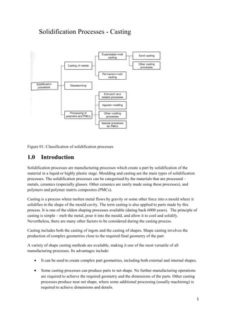
Figure 01: Classification of solidification processes
1.0 Introduction
Solidification processes are manufacturing processes which create a part by solidification of the
material in a liquid or highly plastic stage. Moulding and casting are the main types of solidification
processes. The solidification processes can be categorised by the materials that are processed –
metals, ceramics (especially glasses. Other ceramics are rarely made using these processes), and
polymers and polymer matrix composites (PMCs).
Casting is a process where molten metal flows by gravity or some other force into a mould where it
solidifies in the shape of the mould cavity. The term casting is also applied to parts made by this
process. It is one of the oldest shaping processes available (dating back 6000 years). The principle of
casting is simple – melt the metal, pour it into the mould, and allow it to cool and solidify.
Nevertheless, there are many other factors to be considered during the casting process.
Casting includes both the casting of ingots and the casting of shapes. Shape casting involves the
production of complex geometries close to the required final geometry of the part.
A variety of shape casting methods are available, making it one of the most versatile of all
manufacturing processes. Its advantages include:
• It can be used to create complex part geometries, including both external and internal shapes.
• Some casting processes can produce parts to net shape. No further manufacturing operations
are required to achieve the required geometry and the dimensions of the parts. Other casting
processes produce near net shape, where some additional processing (usually machining) is
required to achieve dimensions and details.
1
2. • Casting can be used to produce very large parts. Castings weighing more than 100 tons have
been made.
• They can be performed on any metal that can be heated to liquid state.
• Some casting methods can be used for mass production.
There are disadvantages associated with casting, which are different for different casting methods.
These disadvantages include limitations on mechanical properties, porosity, poor dimensional
accuracy and surface finish, safety hazards to humans when processing hot molten metals and
environmental problems.
Parts made by casting may vary from small components weighing only a few ounces to huge parts
weighing tons. The list of parts that are cast includes dental crowns, jewellery, statues, wood burning
stoves, engine blocks and heads, machine frames, railway wheels, frying pans, pipes, and pump
housings. A wide variety of metals, ferrous and nonferrous, can be cast.
Plastics and ceramics can also be cast, but the methods and details of the processes differ.
2.0 Overview of casting technology
Casting is usually carried out in the foundry. The foundry is a factory equipped for making moulds,
melting and handling metal in molten form, performing the casting process, and cleaning the finished
casting. The workers who perform casting are called foundrymen.
2.1 Casting process
The mould (used for casting) contains a cavity whose geometry determines the shape of the cast part.
The actual size and shape of the cavity must be slightly oversized to allow for shrinkage that occurs
on the metal during solidification and cooling. Different metals undergo different amounts of
shrinkage. Therefore, if dimensional accuracy is required, the mould must be made for the particular
metal used. moulds may be made of a variety of materials – sane, plaster, ceramic, and metal. Casting
processes are often classified according to the type of mould.
For casting, the metal is first heated to a temperature high enough to completely transform the metal
to liquid state. It is then poured or otherwise directed into the cavity of the mould. In an open mould,
the liquid metal is simply poured till it fills the cavity. In a closed mould, a passageway, called the
gating system, is provided t permit the molten metal to flow from the outside the metal into the cavity.
The closed is by far an important category in casting operations.
As the metal is poured into the mould, it begins to cool. When the temperature drops sufficiently, (to
the freezing point of the pure metal), solidification begins. Solidification is a change of phase, and
time is required to complete it. During this process, the metal assumes the shape of the mould cavity
and many of the properties and characteristics of casting are established.
Once the casting has cooled sufficiently, it is removed from the mould. Depending on the casting
method used, further processing many be required. These processing may include trimming metal
from the cast part, cleaning the surface, inspecting the product, and heat treatment to enhance
properties. In addition, machining may be required to achieve close tolerances on certain part features
and to remove the cast surface.
2
3. Casting processes are divided into two main categories depending on the type of mould used –
expendable mould casting and permanent mould casting. An expendable mould in which the metal
solidifies should be destroyed to remove the casting. These moulds are made of sane, plaster, or
similar materials, whose form is maintained by binders of various kinds. Sand casting is the most
prominent example of expendable mould processes. In sand casting, liquid metal is poured into a
mould made of sand. After the metal hardens, the mould must be sacrificed to recover the casting.
A permanent mould can be used repeatedly to produce many castings. It is usually made of metal
though ceramic is sometimes used (which can withstand the high temperatures of casting. In
permanent mould casting, the mould consists of two or more sections that can be opened to permit the
removal of the casting. Die casting the most commonly used of this group.
More intricate shapes are usually possible with expendable moulds. Part shapes in permanent mould
process are limited by the need to open the mould. However, permanent mould operations have
economic advantages over high production operations.
2.2 Sand casting moulds
This is usually the most important casting process. Many of the features of a sand casting mould are
common to other mould types. The mould consists of two halves – the cop and the drag. The cope is
the upper half and the drag is the lower half. The two parts are contained in a box, called a flask,
which is also divided into two halves, one each for the cope and the drag. The two halves of the
mould separate at the parting line.
In sand casting the mould cavity is formed by the means of a pattern, which is made of wood, metal,
plastic, or other materials and has the shape of the part to be cast. The cavity is formed by packing
sand around the pattern, about half of each in the cope and drag, so that when the pattern is removed,
the remaining void is the desired shape of the cast part. The pattern is usually oversized to allow for
shrinkage. The sand used is usually moist and contains a binder to help it maintain its shape.
The cavity in the mould provides the external surface f the cast part. Casting may also have internal
surfaces. These are determined by the means of a core, a form places inside the mould cavity to define
the interior geometry of the part. In sand casting, although other materials can be used, though other
materials, such as metals, plastics and ceramics.
The gating system is the channel or the network of channels by which molten metal flows into the
cavity from inside the mould. The gating system typically consists of a downsprue (sometimes called
sprue) through which the metal enters a runner that leads into the main cavity. At the top of the
downsprue, the pouring cup is often used to minimise splash and turbulence as the metal flows into
the downsprue. The pouring cup may be a simple cone shaped funnel, but some are designed in the
shape of a bowl which has an open channel leading to the downsprue.
3
4. Figure 02: Two forms the moulds: (a) Open moulds, simply a container in the shape of the desired
part, and (b) closed mould, in which mould geometry is more complex and required a gating system
(passway leading into the cavity.
In addition to this, any casting with significant shrinkage required a riser connected to the main
cavity. The riser is a reservoir in the mould that serves as a source of liquid metal for casting to
compensate for shrinkage during solidification. The riser must be designed to freeze after the main
casting in order to satisfy its function.
As the metal flows into the mould, the air that previously occupied the cavity as well as hot gases
formed by reactions of the molten metal must be evacuated so that the metal can fill the cavity In sand
casting, the natural porosity of the sand mould permits the air and gases to escape through the walls of
the cavity. In permanent metal moulds, small vent holes are drilled into mould or machined into the
parting line to permit the removal of air gases.
3.0 Heating and pouring
To perform casting, the metal must be heated to a temperature somewhat above its melting
temperature and then poured into the mould cavity to solidify.
3.1 Heating
Various furnaces may be used to heat the metal to a molten temperature sufficient for casting. The
heat energy required is the sum of the heat required to
• Raise the temperature of the meta to melting point
• Heat of fusion to convert it from solid to liquid
• Heat to raise the molten metal to the desired temperature for pouring.
This can be expressed as:
H = ρV{Cs(Tm – To) + Hf + Cl(Tp – Tm)}
Where H is the total energy required to heat the metal to casting temperature (J), ρ is the density
(g/cm3), Cs is the the weight specific heat for the solid metal (J/(gK)), Tm is the melting point (K), To
starting temperature (usually ambient) (K), Hf the heat of fusion (J/g), Cl the weight specific heat
4
5. capacity of the metal (J/(gK)), Tp the pouring temperature (K), and V the volume of the metal being
heated.
The computational value of the above equation is limited. The use of the equation is complicated due
to the following factors:
• Specific heat and thermal properties of a solid material may vary with the temperature,
especially if it undergoes a change of phase during heating.
• A metal’s specific heat may be different in the solid and liquid states.
• Most casting metals are alloys, and alloys melt over a range of temperatures between the
solidus and the liquidus rather than at a single point. Therefore, the heat of fusion cannot be
applied so simply.
• The property values required in the equation for a particular alloy may not be available in
most cases.
• There are significant heat losses to the environment during heating.
3.2 Pouring of the metal
After heating, the metal can be poured. Introduction of the molten metal into mould, including its
flow through the gating system and into the cavity is a critical step in the casting process. For this to
be successful, the metal must flow into all regions of the mould before solidifying. Factors that affect
this operation include pouring temperature, pouring rate, and turbulence.
The pouring temperature in the temperature of the molten metal as it is introduced into the mould. The
difference between the pouring temperature and the melting temperature of the metal is important
(liquidus for an alloy). This temperature difference is sometimes referred to as superheat. This also
refers to the amount of heat that must be removed between pouring and when solidification
commences.
The pouring rate refers to the volumetric rate at which the molten metal is poured into the mould. If
the rate is too slow, the metal will chill and freeze before filling the cavity. If the pouring ate is
excessive, turbulence can be a serious problem. Turbulence is characterised by erratic variations in the
magnitude and direction of the velocity through the fluid. The flow is agitated and irregular rather
than smooth and streamlined, as in laminar flow. The turbulent flow should be avoided for several
reasons. It tends to accelerate the forming of metal oxides that can be entrapped during solidification,
degrading the quality of the casting. This also aggravates mould erosion, the gradual wearing away of
the mould surfaces due to the flowing of the molten metal. The densities of most molten metals are
much higher that water. Consequently wear caused by the flow of this metal in the mould is
significant, especially under turbulent conditions. Erosion is especially serious when it occurs in the
main cavity because the geometry of the cast part is affected.
3.3 Engineering analysis of pouring
There are several relationships that govern the flow of liquid metal through the gating system into the
mould. An important relationship is the Bernoulli’s theorem, which states that the sum of energies
(head, pressure, kinetic and friction) at any two points in a flowing liquid are equal. This can be
written as:
5
6. h1 + (p1/ρ1) + v12/(2g) + F1 = h2 + (p2/ρ2) + v22/(2g) + F2
where h = head (cm), p = pressure on the liquid (N/cm2), ρ = density (g/cm3), v=flow velocity(cm/s),
gravitational acceleration constant (cm/g2), F = Head loss due to friction (cm). Subscripts indicate
(two) locations in the liquid flow.
The equation can be simplified in several ways. If friction losses are ignored (though it will obviously
affect the flow in a sand mould) and assume that the system remains at atmospheric pressure
throughout, the equation can be reduced to:
h1 + v12/(2g) = h2 + v22/(2g)
This can be used to determine the velocity of the molten metal at the base of the sprue. If point 1 is at
the top of the sprue and point 2 at the base, If point 2 is used as reference, head at that point = 0, and
h1 us the height of the sprue. When metal is poured into the pouring cup and overflows down the
sprue, the initial velocity at the top of the sprue is zero (v1 = 0). Hence the equation further simplifies
to
h1 = v22/2g
which gives
v = √(2gh)
where v is the velocity of the metal at the base of the sprue and h is the height of the sprue.
Another important relation in pouring is the continuity law, which states that the volume of flow
remains constant throughout the liquid. The volume flow rate is equal to the velocity multipled by the
cross-sectional area of the flowing liquid. This can be expressed as
Q = v1A1 = v2A2
Where Q = volumetric flow rate (cm3/s), A = cross sectional area of liquid (cm2)Therefore, an
increase in area results in a decrease in velocity and vice versa.
The sprue could be tapered. As the metal accelerates during its descent into the sprue opening, the
cross sectional area of the channel must be reduced. Otherwise, as the velocity of the flowing metal
increases towards the base of the sprue, air can be aspirated into the liquid and conducted into the
mould cavity. To prevent this, the sprue is designed with a taper, so that the volume flow rate vA is
the same at the top and bottom of the sprue.
Assuming the runner from the sprue base to the mould cavity is horizontal ( and therefore head h is
the same as the sprue base), then the volume rate of flow through he gate and into the mould cavity
remains to vA at the base. Accordingly, the time required to fill a mould cavity of volume V can be
estimated as
TMF = V/Q
Where TMF = the mould filling time (s), V = volume of the mould cavity (cm3), Q = is the volume flow
rate. The mould filling time is computed by the above equation is the minimum. This is because
frictional losses and possible constriction of the flow in the gating system.
3.4 Fluidity
6
7. The molten metal flow characteristics are described by the term fluidity, which is a measure of the
capability of a metal to flow into and fill the mould before freezing. Fluidity is the inverse of
viscosity. Standard testing methods are available to asses fluidity. One is the spiral mould test shown
below. The fluidity is indicated by the length of the solidified metal in the spiral. The longer cast
spiral means greater fluidity of the molten metal.
Figure 03: Spiral mould test for fluidity, where fluidity is measured as the length of the spiral channel
that is filled by the molten metal prior to solidification.
Factors affecting fluidity include pouring temperature relative to melting point, metal composition,
viscosity of the liquid metal, and heat transfer to surrounding. A higher pouring temperature relative
to the freezing point of the metal increases the time it remains in liquid state, allowing it to flow
further before freezing. This tends to aggravate certain casting problems such as oxide formation,
porosity, and penetration of liquid metal into interstitial spaces between the grains of sand forming the
mould. The last problem causes the surface of the casting to contain embedded sand particles, making
it rougher and abrasive than normal.
Composition also affects fluidity, particularly with respect to the metal’s solidification mechanism.
The best fluidity is obtained by metals that freeze at a constant temperature (pure metals and eutectic
alloys). When solidification occurs over a temperature range (most alloys), the partially solidified
portion interferes with the flow of the liquid portion, reducing fluidity. In addition to the freezing
mechanism, this also determines the heat of fusion – the amount of heat required to solidify the metal
on the liquid state. A higher heat of fusion tends to increase the measured fluidity in casting.
4.0 Solidification and cooling
After pouring into the mould, the molten metal cools and solidifies. Issues associated with
solidification include the time for the metal to freeze, shrinkage, directional solidification, and riser
design.
4.1 Solidification of metals
The solidification process depends on whether the metal is a pure element or an alloy.
4.1.1 Pure metals
A pure metal solidifies at a constant temperature equal to its freezing point, which is the same as its
melting point. The melting point of pure metals are well known an documented. The process occurs
over time as shown in the cooling curve below. The actual freezing takes time, known as local
solidification time in casting, during which the metal’s latent heat of fusion is released into the
surrounding mould. The total solidification time is the time taken between pouring and complete
7
8. solidification. After casting has completely solidified, cooling continues at a rate indicated by the
downward slope of the cooling curve.
Because of the chilling action of the mould wall, a thin skin of solid metal is initially formed at the
interface immediately after pouring. The thickness of the skin increases to form a shell around the
molten metal as solidification progresses inwards towards the centre of the cavity. The rate at which
freezing proceeds depends on the thermal properties of the metal.
The metal that forms the initial skin is cooled rapidly by the extraction of heat through the mould
wall. This cooling action causes the grains of the skin to be fine, equiaxed, and randomly oriented. As
cooling continues, further grain formation and growth occur in the direction away from heat transfer.
Since heat transfer Since the heat transfer is through the skin and the wall, grains grow inwards as
needles or spines of solid metal. As these spines enlarge, lateral branches form at right angles to the
first branches. This type of grain growth is referred to as dendritic growth, and it occurs not only in
the freezing of pure meals but alloys as well. These treelike structures are gradually filled in during
freezing as additional metal is continually deposited on the dendrites until complete solidification has
occurred. The grains resulting form dendritic growth take on a preferred orientation, tending to be
coarse, columnar grains aligned towards the centre of the casting.
Figure 04:
Cooling curve for a pure metal during casting
Figure 05:
Characteristic grain structure in a casting of a pure metal, showing randomly oriented grains of small
size near the mould wall, and large columnar grains oriented toward the centre of the casting.
4.1.2 Most alloys
8
9. Most alloys freeze over a temperature range rather than at a single temperature. The exact range
depends on the alloy system and the particular composition. Solidification of an alloy can be
explained with reference to figure 06 which shows the phase diagram for an alloy system and the
cooling curve for a given composition. As the temperature drops, freezing begins at the liquidus
temperature and completes when the solidus temperature is reached. The start of freezing is similar to
a pure metal. A thin skin is formed on the surface due to the large temperature gradient of the surface.
The freezing the continues as before by the growth of dendrites from the walls. However, owing to the
temperature spread between the liquidus and solidus, the nature of dendritic growth is such that an
advancing zone is formed where both liquid and solid states coexist. The solid portions are dendrite
structures that have formed sufficiently to trap liquid metal in the matrix. This region has a soft
consistency that has motivated its name as the mushy zone. Depending on the conditions of freezing,
the mushy zone can be relatively narrow, r it can exist throughout most of the casting. The latter
condition is promoted by factors such as slow heat transfer out of the metal and a wide difference
between liquidus and solidus temperatures. Gradually, the liquid islands in the dendrite matrix
solidify as the temperature of the casting drops to the solidus for given alloy compositions.
Another factor that complicates solidification is the composition at which the dendrites start to form
favours the metal with the higher melting point. As freezing continues and dendrites grow, there
develops an imbalance in composition between the metal that has solidified and the remaining molten
metal. This composition imbalance is finally manifested in the completed casting in the form of
segregation of elements. Segregation can be microscopic and macroscopic. At microscopic level, the
chemical composition varies throughout each individual grain. This is due to the fact that the
beginning spine of each dendrite has a higher proportion of one element in the alloy. As the dendrite
grown in its local vicinity, it must expand using the remaining liquid metal that has been partially
depleted of the first component. Finally, the last metal to freeze in each grain is which has been
trapped by the branches of the dendrites, and its composition is even further out of balance. Therefore,
there are variations of composition within a single grain of casting.
Figure 06: (a) Phase diagram for copper-nickel alloy system, (b) associated cooling curve for a 50%
Ni-50%Cu composition during casting.
The composition also varies at macroscopic level throughout the entire casting. The regions of the
casting that freeze first are richer in one component than the other, the remaining molten metal is
deprived of one component when freezing occurs in the interior. Therefore, there is a general
segregation throughout the cross-section of the casting, sometime called ingot segregation.
9
10. Figure 07: Characteristic grain structure in an alloy casting, showing segregation of alloying
components in the centre of the casting.
4.1.3 Eutectic alloys
These constitute an exception to the general process by which alloys solidify. Eutectic alloys have the
same liquidus and solidus temperatures, therefore solidification occurs at a constant temperature. The
effect can be seen in the lead tin phase diagram below. The composition of 61.9% tin and 38.1% lead
has a melting point of 183oC (which is lower than the melting point of both pure metals. This is
known as the eutectic composition of the system and the melting point the eutectic temperature. Lead
tin alloys are not commonly used in casting, but lead tin combinations near eutectic are used for
soldering, where low melting point is an advantage. Eutectic alloys used in casting include aluminium
silicon - 911.6% Si and cast iron (4.3%C).
4.2 Solidification time
Regardless of whether a casting is a pure metal or alloy, solidification takes time. The total
solidification time is the time required for the casting to solidify after pouring. The time is dependent
on the size and shape of the casting by an empirical relationship known as Chvorinov’s rule, which
states
TTS = Cm (V/A)n
Where TTS is the total solidification time (min), V = volume of casting (cm2), n is usually take to have
the value n, Cm is the mould constant. When n = 2, units of C are min/cm2 and its value depends on
the particular conditions of the casting operation, including mould material (specific heat, specific
conductivity), thermal properties of the cast metal ( heat of fusion, specific heat, thermal
conductivity), and pouring temperature relative to the melting point of the metal. The value of Cm for
a particular casting can be based on experimental data from previous operations carried out using the
same mould material, metal, and pouring temperature, even though the shape of the part may be
different.
This equation predicts that a casting with a higher volume to surface ratio will cool and solidify more
slowly than one with a lower ratio. This is put to good use when designing the riser in the mould. To
feed molten metal into the casting, the riser must remain liquid longer than the rest of the casting (TTS
for the casting for the riser must be larger for the riser). As the mould conditions are similar for both,
Cm will be same. By designing the riser to have a larger volume to area ratio, the main casting can be
designed to solidify first and the effect of shrinkage are minimised.
4.3 Shrinkage
10
11. Shrinkage occurs during cooling an freezing. It occurs in three steps – liquid contraction during
cooling (before solidification), Contraction during phase change (solidification shrinkage, and thermal
contraction of solid cast.
These can be explained with reference to a cylindrical casting in an open mould. The cooling of the
liquid causes the height of liquid in the mould to decrease. The amount of liquid contraction is about
0.5%.Solidification shrinkage has two effects. It censuses a further reduction of the height of the
casting, and the amount of liquid metal available to feed the top centre portion on the casting becomes
restricted. This is usually the last region to freeze, and the absence of metal creates a void in the
casting in this location. This is called a pipe by foundrymen. Once solidified, the casting experiences
further contraction in height and diameter while cooling. This is determined by the metal’s coefficient
of thermal expansion, which is applied to reverse the determine contraction.
The table below gives the volumetric contraction for casting metals due to solidification shrinkage
and solid contraction. Solidification contraction occurs in nearly all metals as the solid phase has a
higher density than the liquid phase. The phase transformation that accompanies solidification causes
a reduction in the volume per unit weight of metal. The exception is cast iron containing a high
carbon content, whose solidification is complicated by a period of graphitization during the final
stages of freezing, which tends to counteract the volumetric decrease associated with solidification.
Figure 08: Shrinkage of a cylindrical casting during solidification and cooling: (0) Starting level of
molten metal immediately after pouring, (1) Reduction in level caused by liquid contraction during
cooling, (2) reduction in level caused by liquid contraction during cooling, (3) further reduction in
height and diameter due to thermal contraction during cooling of the solid metal. For clarity,
dimensional reductions are exaggerated.
11
12. Table 01: Volumetric contraction of different casting metals due to solidification shrinkage and solid
contraction
Metal Volumetric contraction due to, %
Solidification shrinkage Solid thermal conduction
Aluminium 7.0 5.6
Al alloy (typical) 7.0 5.0
Gray cast iron 1.8 3.0
Gray cast iron, high C 0 3.0
Low C cast steel 3.0 7.2
Copper 4.5 7.5
Bronze (Cu-Sn) 5.5 6.0
Pattern makers account for shrinkage by making oversized mould cavities. The amount the mould
should be made larger relative to the final casting is called pattern shrinkage allowance. Although
shrinkage is volumetric, the dimensions of the casting are almost always expressed linearly, so the
allowances must be applied accordingly. Special shrink rules with slightly elongated scales are used
to make moulds larger than the desired casting by the appropriate amount. Depending on the metal to
be cast, the shrink rules are between 1% and 5% longer.
4.4 Directional solidification
To minimise the effects of shrinkage, it is desirable for the regions of the casting most distant from
the liquid metal supply to freeze first and for solidification to progress from these remote regions to
the risers, to ensure that liquid metal are available from the risers to prevent shrinkage voids during
freezing. The term directional solidification is used to describe this aspect of casting and the method
by which it is controlled. The desired directional solidification is achieved by observing Chvorinov’s
rule in designing the casting, its orientation and the riser system that feeds it. For example, areas with
low V/A can be located away from the riser, so that these regions freeze first and the supply of liquid
metal for the rest of the casting will remain open until the bulkier sections solidify.
Another possible method is the usage of chills – internal or external heat sinks that cause rapid
freezing in certain regions of the casting. Internal chills are small metal parts placed inside cavity
before pouring so that molten metal will solidify first around these parts. The internal chill should
have a chemical composition similar to the metal being poured, most readily achieved by making the
chills out of the same material as the casting.
External chills are metal inserts in the walls of the mould cavity that can remove heat from the molten
metal more rapidly than the surrounding sand in order to promote solidification. They are often used
effectively in sections of the casting difficult to feed with liquid metal, thus encouraging rapid
freezing in this sections while connection to the liquid metal is still open.
12
13. Figure 09: (a) external chill to encourage rapid freezing of the molten metal in a thin section of the
casting, (b) likely result if the external chill were not used.
It is also important to avoid premature solidification in regions near the riser. Of particular concern is
the passway between the riser and the main cavity. This connection is designed in such a way that it
does not freeze before casting, which does not isolate the casting from the molten metal in the riser.
Though it is generally desirable minimise the volume in connection (to reduce waste), the cross-
sectional area must be sufficient to delay the onset of freezing. This is usually aided by making the
passway short in length, so that it absorbs heat from the molten metal in the riser and the casting.
4.5 Riser design
Risers can also be designed in several forms. A side riser is attached to the side of the casting by the
means of a small channel. A top riser is connected to the top surface of the casting. Risers can be open
or blind. An open riser is exposed to the outside at the top surface of the cope. This has the
disadvantage of allowing more heat to escape, promoting faster solidification. A blind riser is entirely
enclosed in the mould.
5.0 Sand casting
Metal casting processes can be divided into two categories – expendable mould and permanent mould.
In expendable mould casting, the mould must be sacrificed to remove the cast part. As a new mould
each required for each casting, production rates depend on the time required to make the mould rather
than time required for the casting itself. However, for some parts, moulds can be produced and casting
made at a rate of 400 parts per hour or higher.
Sand casting is an expendable mould casting process. It is also the most widely used casting process,
accounting for a significant majority of all parts cast. Nearly all alloys can be sand cast, and is one of
the few processes that can be used for metals with high melting temperatures such as steel, nickel and
titanium. Its versatility permits casting of parts ranging in size from small to large in production
quantities from one to millions.
Sand casting consists of pouring the molten metal into a sad mould, allowing the metal to solidify,
and then breaking the mould to remove the casting. The casting must then be cleaned and inspected,
and heat treatment is required to improve metallurgical properties. The cavity in sand casting is
produced by packing sand around a pattern (an approximate duplicate of the part to be cast) and
removing the pattern by separating the mould to two halves. The mould also contains a gating and
riser system. In addition, if the casting has internal surfaces (hollow parts or parts with holes, a core
must be included in the loud. As the mould is sacrificed to remove the casting new mould must be
13
14. made for each part Therefore, sand casting seems to include not only the casting operation, but also
the fabrication of patter and making the mould.
5.1 Patterns and cores
Sand casting requires a pattern, which is a full side model of the part, enlarged to account for
shrinkage and machining allowances in the final casting. Materials used to make patterns include
wood, plastics and metals. Wood is a common pattern material because it is easily worked into shape.
Its disadvantages are the tendency to warp, and it is abraded by the sand being compacted about it,
which limits the number of times it can be reused. Metal patterns are more expensive, but they last
longer. Plastics are a compromise between wood and metal. Selection of the appropriate material
mostly depends on the total quality of the castings to be made.
The simplest patterns are made of one piece, called a solid pattern. Although it is the easiest pattern to
fabricate, it is not the easiest to use in making the sand mould. Determining the location of the parting
line between the two halves can be a problem, and incorporating a gating system and sprue into the
mould is left to the judgement and skill of the foundry worker.
Split patterns usually consist of two pieces, dividing the part along a plane coinciding with the parting
line of the mould. Split patterns are appropriate for complex part geometries and moderate production
quantities. The parting line of the mould is predetermined by the two pattern halves, rather than by
operator judgement.
For higher production rates, match plate or cope and drag patterns are employed. In match plate
patterns, the two pieces are attached to the opposite sides of a wood or metal plate. Holes in the plate
allow the cope and drag (top and bottom sections of the mould) to be aligned accurately. Cope and
drag patterns are similar expect that the split halves are attached to separate patterns, so that the cope
and drag can be fabricated independently, instead of using the same tooling for both.
Figure 10: Types of pattern used in sand casting (a) solid pattern, (b) split pattern, (c) match-plate
pattern, (d) cope and drag pattern
If the casting is to have internal surfaces, a core is required. A core is a full-scale model of the interior
surfaces of the part. It is inserted into the mould cavity prior to pouring so that the molten metal will
flow and solidify between the moulding cavity prior to pouring, so that the molten metal will flow and
solidify between the mould cavity and the core to form the casting’s external and internal surfaces.
The core is usually made of sand and compacted to the desired shape. As with the pattern, the actual
size of the core must allow for shrinkage and machining. Depending on the geometry of the part the
core may or may not require supports to hold it in position in the mould cavity during pouring. These
supports, called chaplets, are made of a metal with a higher melting temperature than the casting
metal. On pouring and solidification, the chaplets are bonded into the casting. The portion of chaplet
protruding from the casting is subsequently cut off.
14
15. Figure 11: (a) Core held in place in the mould cavity by chaplets, (b) possible chaplet design, (c)
casting with internal cavity.
5.2 Moulds and mould making
Foundry sands are silica (Si2O) or silica mixed with other minerals.. The sand should posses good
refractory properties – capacity to stand up under high temperatures without melting or otherwise
degrading, Important features of sand include grain size, distribution of grain size in the mixture the
shape of individual grains. Small grains provide a better surface finish on the cast part, but large grain
sizes are more permeable to allow the escape of gases during pouring. Most moulds made from grains
of irregular shape tend to be stronger that moulds of round grains due to interlocking but it tends to
restrict permeability.
When making the mould, the grains of sand are held together by a mixture of water and bonding clay.
A typical mixture by volume is 90% sand, 3% water, and 7% clay. Other binding agents (other than
clay, such as organic resins (phenolic resins) and inorganic binders (e.g., sodium silicate and
phosphate) may be used. In addition to the sand and the binder, additives are sometimes added to
enhance properties such as strength and/or permeability of the mould.
To form the mould cavity, the traditional method is to compact the moulding sand around the pattern
for both cope and drag in a container called flask. The packing process is performed by various
methods. The simplest is hand ramming, accomplished manually by a foundry worker. In addition,
various machines have been developed to mechanise the packing procedure. These machines operate
by several mechanisms, including squeezing sand around the pattern by pneumatic pressure, a jolting
action in which sand which is contained in a flask with the patter is dropped repeatedly in order to
pack it into place, or a slinging action where the sand grains are impacted against the pattern at high
speed.
An alternative to traditional flasks for each sand mould is flaskless moulding, which refers to the use
of one master flask in a mechanised system of mould production. Each sand mould is produced using
the main master flask. Mould production rates up to 600 per hour are claimed for this automated
method.
Several indicators are used to determine the quality of the sand mould:
• Strength: the mould’s ability to maintain its shape and resist erosion caused by the flow of
molten metal. It depends on grain shape, adhesive qualities of the binder, and other factors
• Permeability: Capacity of the mould to allow hot air and gases from the casting operation to
pass through the voids in the sand.
15
16. • Thermal stability: ability of the sand at the surface of the mould cavity to resist cracking and
buckling upon contact with molten metal
• Collapsibility: Ability of the mould to give away and allow the casting to shrink without
cracking the casting. It also refers to the ability to remove sand from the casting during
cleaning
• Reusability: whether the sand from the broken casting be reused for other moulds.
These parameters may be incompatible – for example, a strong mould may be less collapsible.
Sand moulds can be classified as green-sand, dry-sand, or skin-dried moulds. Green sand moulds are
made of a mixture of sand, clay and water, and the word green refers to the fact that the mould
contains moisture at the time of pouring. Green sand moulds generally have sufficient strength for
most applications, good collapsibility, good permeability, good reusability, and are the least expensive
of all moulds. They are the most widely used mould type, but then have their problems. The moisture
in the mould may cause defects in some castings, depending on the metal and the geometry of the
part. A dry sand mould is made using organic binders rather than clay, and the mould is baked in a
large oven at temperatures ranging from 200 to 320oC. Oven baking strengthens the mould and
hardens the cavity surface. A dry-sand mould provides better dimensional control in the product
compared to green moulding. However, dry sand is more expensive and the production rate is reduces
because of the drying time. Applications are generally limited to medium and large casting in low to
medium production rates. In a skin dried mould, the advantaged of a dry sand mould partially
achieved by drying the surface of a green sand mould to a depth of 10 to 25 mm at the mould cavity
surface, using torches, heating lamps, or other means. Special bonding materials must be added to the
sand mixture to strengthen the cavity surface.
The preceding mould classifications refer to the use of conventional binders consisting of either clay-
and-water or those that require heating to cure. In addition to these, chemically bonded moulds have
been developed that are not based on either of these traditional binding ingredients. Some of the
binders used in these no bake systems include furan resins (consisting of furfural alcohol, urea, and
formaldehyde), phenolics, and alkyd oils. No-bake moulds are growing in popularity due to their good
dimensional control in high production applications.
5.3 The casting operation
After the core is positioned (if one is used) and the two halves are clamped together, and then casting
is performed. Casting consists of pouring, solidification, and cooling of the cast part. The gating and
the riser system must be designed to deliver liquid metal into the cavity and provide for sufficient
reservoir of molten metal during solidification shrinkage. Air and gases must be allowed to escape.
One of the hazards during pouring is that the buoyancy of the molten metal can displace the core
according to Archimedes’ principle. The force tending to lift the core is equal to the weight of the
displaces liquid less than the weight of the core:
Fb = Wm – Wc
Where Fb is the buoyancy force, Wm is the weight of molten metal displaced, and Wc the weight of the
core. The weights are determines as volume of the core multiplied by the density of the core material
and the metal being cast. The density of the sand core is around 1.6 g/cm3.
16
17. Table 02: Density of selected casting alloys
Material Density (g/cm3) Material Density (g/cm3)
Aluminium (99% pure) 2.70 Cast iron, gray 7.16
Aluminium silicon alloy 2.65 Copper (99% pure) 8.73
Aluminium copper (92% Al) 2.81 Lead pure 11.30
Brass 8.62 Steel 7.82
Following solidification and cooling, the sand mould is broken away from the casting to remove the
part. Then it is cleaned, gating and riser systems separated, and sand is removed. The casting is then
inspected.
6.0 Other expendable mould casting processes
Though sand casting is versatile, other casting processes have been developed for special needs. The
difference between these methods are in composition of the mould material, or the manner in which
the mould is made, or the way the pattern is made.
6.1 Shell moulding
This is casting process where the mould is thin shell (~9 mm) made of sand held together by
thermosetting resin binder. It was developed in the early 1940s in Germany.
There are many advantages of the shell moulding process. The surface of the shell mould cavity is
smoother than a conventional green sand mould and this permits easier flow of molten metal during
pouring and better surface finish on the final casting. Finished of 2.5 μm can be achieved, as well as
good dimensional accuracy (with tolerances of ±0.25 mm possible on small to medium sized parts).
The good finish and accuracy often preludes the need for further machining. Collapsability of the
mould is generally sufficient to avoid tearing and cracking of the casting.
Disadvantages include a more expensive metal pattern than used for green sand moulding. This makes
the process difficult to justify for small quantities of parts. Shell moulding can be mechanised for
mass production and is very economical for very large quantities. It is particularly suited to steel
castings led that 20 lb. Examples of parts made using shell moulding include gears, valve bodies,
bushings, and camshafts.
17
18. Figure 12: Steps in shell moulding. (1) A match plate or cope-and-drag pattern is heated and placed
over a box containing sand mixed with thermosetting resin, (2) box is inverted so that the sand and
resin fall onto the hot pattern, causing a layer of mixture to partially cure on the surface to form a hard
shell, (3) the box is repositioned so that the loose, uncured particles drop away, (4) Sand shell is
heated in oven for several minutes to complete the curing, (5) Shell mould is stripped from the
pattern, (6) Two halves of the shell mould are assembled, supported by sand or metal shot in a box,
and pouring is accomplished. The finished casting with sprue is removed as shown in (7).
6.2 Vacuum moulding
Vacuum moulding, also called V-process, was developed in Japan around 1970. It uses a sand mould
held together by vacuum pressure rather than by a chemical binder. Recovery of sand is one of the
advantages of vacuum moulding, as no binders are used. Also, the sand does not require extensive
mechanical reconditioning normally done when binders are used to mould sand. As no water is mixed
with the sand, moisture related defects are absent. Disadvantages of the V-process are it is relatively
slow and not adaptable to mechanisation.
18
19. Figure 13: Steps in vacuum moulding: (1) A thin sheet of preheated plastic is drawn over a match
plate or cope-and-drag pattern by vacuum. The pattern has small vent holes to facilitate vacuum
forming. (2) A specially designed flask is placed over the pattern plate and filled with sand, and a
sprue and pouring cup are formed in the sand. (3) Another thin plastic sheet is placed over the flask,
and a vacuum is drawn that causes the sand grains to be held together, forming a rigid model. (4) the
vacuum on the mould pattern is released to permit the pattern to be stripped from the mould. (5) This
mould is assembled with its matching half to form the cope and drag, and with vacuum maintained on
both halves, pouring can be achieved. The plastic sheets burns quickly on contacting the metal After
solidification, nearly all the sand be recovered for reuse.
6.3 Expanded polystyrene process
The expanded polystyrene casting process uses a mould of sand packed around a polystyrene foam
pattern that vaporises when the molten metal is poured into the mould. This process is also known as
lost-foam process, lost pattern process, evaporative foam process, and full mould process (this is the
trade name). The polystyrene pattern includes the sprue, risers, and gating system and it may also
contain internal cores, eliminating the need for a separate core. Also, since, the foam pattern itself
becomes cavity in the mould, considerations of draft and parting lines can be ignored. The mould does
not have to be opened into cope and drag sections. The sequence in this casting process is illustrated
in figure 13. Various methods for making a pattern are used, depending on the quantities of castings
to be produced. For one-of-a-kind castings, the foam is manually cut from large strips and assembled
to form the pattern. For large production runs, and automated moulding operation can be set up to
mould the patterns prior to casting. The pattern is usually coated with a refractory compound to
produce a smoother surface on the pattern and to improve high temperature resistance.
Moulding sands usually include bonding agents. However, dry sand is used in certain processes in this
group, which aids recovery and reuse.
A significant advantage is that the pattern need not be removed from the mould. This simplifies and
expedites mould making. In a conventional green sand mould, two halves are required with proper
parting lines, draft allowances must be made, cores must be inserted, and the gating and riser system
19
20. must be built. With expanded polystyrene, these steps are added into the pattern itself. The
disadvantage is that a new pattern in needed for every casting. The economic justification is highly
dependent on the cost of producing patterns. This has been applied to mass produce castings for
automobile engines. Automated production systems are installed to mould the polystyrene foam
patterns for these applications.
Figure 14: Expanded polystyrene casting process: (1) pattern of polystyrene is coated with refractory
compound, (2) foam pattern is placed in mould box, (3) Molten metal is poured into portion of the
pattern that forms pouring cup and sprue. As the metal enters the mould, the polystyrene is vaporised
ahead of the advancing liquid, allowing the resulting the mould cavity to be filled.
6.4 Investment casting
In investment casting, a pattern made of wax is coated with a refractory material to make the mould,
after which wax is melted away prior to pouring the metal. It is a precision casting process because it
is capable of making castings of high accuracy and intricate detail. It is also known as lost wax
casting, as the wax pattern is lost before the casting.
The lost wax casting process was developed by ancient Egyptians about 3500 years ago. Although
who invented this process is not recorded, historians speculate that it resulted from the close
association between pottery and moulding in early times. It was the potter who crafted the moulds
used for casting. The core was made of clay in the general shape of the piece and then a wax coating
was given. The wax proved to be an easy material to form intricate designs and shapes could be
created. On the surface, several layers of clay were carefully plastered to hold the resulting
components together. Then the mould was baked in a kiln, so that the clay hardened and the way
melted and drained away to forma cavity. At last, molten bronze was poured into the cavity. After
casting, the mould was broken away to retrieve the casting.
Steps in modern investment casting is shown in figure 15. As the wax pattern in lee doss after the
refractory pattern is made, a separate pattern is required for every casting. Pattern production is
usually accomplished by a moulding operation – pouring or injection hot wax into a master die that
has been designed with proper allowances for both wax shrinkage and subsequent metal casting. In
cases where the part geometry is complicated, several wax pieces must be joined together to make the
pattern. In high production operations, several patterns are attached to a sprue, also made of wax, to
form a pattern tree, which is the geometry which will be cast out of metal.
Coating with refractory is usually accomplished by dipping the pattern tree into a slurry of very fine
grained silica or other refractory (almost powder form) mixed with plaster to bond he mould into
shape. The small grain size of the refractory material provides a smooth surface and captures the
intricate details of the wax pattern. The final mould is accomplished by repeatedly dipping the tree
20
21. into the refractory slurry or by gently packing the refractory around the tree in a container. The mould
is allowed to air dry for about 8 hours to harden the binder.
Figure 15: Steps in investment casting: (1) wax patterns are produced, (2) Several patterns are
attached to a sprue to form a pattern tree, (3) The pattern tree s coated with a thin layer of refractory
metal, (4) the full mould is formed by covering the coated tree with sufficient refractory material to
make it rigid, (5) The mould is held in an inverted position and heated to melt the wax and permit it to
drip out of the cavity, (6) the mould is preheated to a high temperature, which ensures that all
contaminants are eliminated from the mould. It also permits liquid metal to flow more easily into the
detailed cavity. The molten metal is poured and it solidifies, (7) the mould is broken away from the
finished casting. Parts are then separated from the sprue.
Advantages of investment casting are:
• Parts of great complexity and intricacy can be cast
• Close dimensional control – tolerances of ±0.075 mm are possible
• Good surface finish is possible
• Additional machining is not normally required as it is a net shape process.
Because many steps are involved in this casting operation, it is relatively expensive. Parts made by
investment casting are generally small in size, tough parts with complex geometries weighing up to 75
lb have been successfully cast. All types of metal, including steels, stainless steels, and other high
temperature alloys can be investment cast. Examples include complex machinery parts, blades, and
other components for turbine engines, jewellery, and dental fixtures.
6.5 Plaster-mould and ceramic mould casting
Plaster mould casting is similar to sand casting except that the mould is mad of plaster of Paris
(gypsum – CaSO4-2H2O) instead of sand. Additives such as talc and silica flour are mixed with plaster
to control contraction and setting time, reduce cracking, and increase strength. To make the mould,
21
22. the plaster mixture combined with water is poured over a plastic or metal pattern in a flask and
allowed to set. Wood patterns are generally unsatisfactory due to extended contact with water in the
plaster. The fluid consistency permits the plaster mixture to readily flow around the pattern, capturing
its details and surface finish. Thus the cast product in plaster moulding is noted for these attributes.
Curing us one of the disadvantages of this method, at least for high production. The mould must be set
for about 20 minutes before the pattern is stripped. The mould is then baked for several hours to
remove moisture. Even with baking, not all of the moisture is removed. The problem is that the mould
strength is reduced when the plaster is too dehydrated but moisture content can cause defects in the
product. A balance must be achieved between these. Another disadvantage is that the mould is not
permeable, limiting the escape of gases from the mould cavity. This can be solved in several ways:
• Evacuating the mould cavity before pouring
• Aerating the plaster slurry prior to mould making so that the resulting hard plaster contains
finely dispersed voids.
• Using a special mould composition and treatment known as Antioch process. This involves
using about 50% sand mixed with plaster, heating the mould in an autoclave, (an oven that
uses superheated steam under pressure), and then drying. The resulting mould has
considerably greater permeability that the conventional plaster mould.
Plaster moulds withstand the same high temperature as sand moulds. They are therefore limited to the
casting of lower-melting point alloys, such as aluminium, magnesium, and some copper based alloys.
Applications include metal moulds for plastic and rubber moulding, pump and turbine impellers, and
other parts of relatively intricate geometry. Castings range from 20 g to more than 100 kg. Parts
weighing less than 10 kg are common. Advantages of plaster moulding for these applications are good
surface finish and dimensional accuracy and the capability of thin cross-sections in casting.
Ceramic mould casting is similar to plaster mould casting, except that the mould is made of refractory
ceramic materials that can withstand higher temperature that plaster. Thus ceramic moulding can be
used to cast steels, cast irons, and other temperature alloys. Its applications (mould and relatively
intricate parts)are similar to those of plaster mould casting except for the metals cast. Its advantages
(good accuracy and finish) are also similar.
7.0 Permanent mould casting processes
In this group, the mould is fabricated out of metal or some other durable metal and is used for many
castings. Permanent mould casting can considered the basic in a group of casting processes that use
reusable moulds. Others in this group include die casting and centrifugal casting.
7.1 The basic permanent mould process
This uses a metals mould constructed of two sections that are designed for easy, precise opening and
closing. The moulds are commonly made of steel or cast iron. The cavity, with the gating system
included, is machined into the two halves to produce accurate dimensions and good surface finish.
Metals commonly cast in permanent moulds include Aluminium, Magnesium, copper-base alloys, and
cast irons. However, cast iron requires a high pouring temperature (1250 – 1500oC) which affects
mould life. The very high pouring temperatures of steel makes permanent moulds unsuitable for it,
unless it is made of refractory material.
22
23. Cores can be used in permanent moulds to form interior surfaces in the cast product. The cores can be
made of metal, but either their shape must allow for removal from the casting pr they must be
mechanically collapsible to permit removal. If the withdrawal of a metal core is difficult, a sand core
can be used, in which case the process becomes semi-permanent mould casting.
Figure 16: Steps in permanent mould casting: (1) mould is preheated and coated, (2) cores (if used)
are inserted, and mould is closed, (3) molten metal is poured into the mould, and the mould is opened.
(5) shows the finished part.
Steps in the permanent mould casting process are shown in figure 16. In preparation for casting, the
mould is first preheated and one or more coatings are sprayed into the cavity. Preheating facilitates
metal flow through the gating system and into the cavity. The coating aid heat dissipation and
lubricate the mould surfaces for easier separation of the cast product. After pouring, as soon as the
metal solidifies, the mould is opened and the casting is removed. Unlike expendable moulds,
permanent moulds do not collapse, so the mould must be opened before appreciable cooling
contraction, occurs in occurs in order to prevent cracks from developing in the casting.
Advantages of permanent mould casting include close dimensional control. Also, he more rapid
solidification caused by the metal mould results in a finer grain structure, so the castings are stronger.
This is generally limited to metals of lower melting points. Other limitations include simple part
geometries compared to sand casting (because of the need to open the mould. Because mould cost is
substantial, the process is best suited to high-volume production and can be automated accordingly.
Atypical parts include automotive pistons, pump bodies, and certain castings for aircraft and missiles.
7.2 Variations of permanent mould casting
Several casting processes are similar to the permanent mould method. These include slush casting,
low pressure casting, and vacuum permanent mould casting.
23
24. 7.2.1 Slush casting
This is a permanent mould casting method in which a hollow casting is formed by inverting the mould
after partial freezing at the surface to drain out the liquid metal in the centre. Solidification begins
mould walls because they are relatively cool, and it progresses over time towards the middle of the
casting. Thickness of the shell is controlled by the length of time allowed before draining. Slush
casting is used to make statues, lamp pedestals, and toys out of low melting point metals such as lead,
zinc, and tin. In these, external appearance is important, but strength and interior geometry are minor
considerations.
7.2.2 Low pressure casting
In basic permanent mould casting and slush casting, the flow of metal into the mould is caused by
gravity. In low pressure casting, the liquid metal is forces into the cavity under low pressure,
approximately 0.1 MPa from beneath so that the flow is upwards. The advantage is the clean molten
metal from the centre of the ladle is introduced to the mould, rather than those exposed to air. Gas
porosity and oxidation defects are minimised and mechanical properties are improved.
Figure 17: Low-pressure casting. The diagram shows how air pressure is used to force the molten
metal in the ladle upwards into the mould cavity. Pressure is maintained until the casting has
solidified.
7.2.3 Vacuum permanent mould casting
This is a variation of low-pressure casting in which vacuum is used to draw the molten metal into the
metal cavity. The general configuration is similar to the low pressure casting operation. The
difference is that reduced air pressure from the vacuum in the mould is used to draw the liquid metal
into the cavity, rather than forcing it by positive air pressure from below. There are several befits of
the vacuum technique relative to low pressure casting – air porosity and related effects are reduced,
and greater strength is given to the cast product.
7.3 Die casting
This is a permanent mould casting operation where the molten metal is injected into the mould under
high pressure. Typical pressures are 7 to 350 MPa. He pressure is maintained during solidification,
after which the mould is opened and the part is removed. The moulds in this operation are called dies
24
25. (hence the name die casting). The use of high pressure is to force the metal into the die cavity in the
most notable feature that distinguishes this process from others in the permanent mould category.
Die casting operations are carried out in special die casting machines. Modern die casting machines
are designed to hold and accurately close the two halves of the mould, and keep them closed while the
liquid metal is forces into the cavity. There are two main types of die casting machines: (1) hot
chamber and (2) cold chamber, differentiated by how the molten metal is injected into the cavity.
Figure 18: General configuration of a cold chamber die casting machine
Figure 19: Cycle in hot chamber casting: (1) with die closed and plunger withdrawn, molten metal
flows into the chamber, (2) plunger forces metal into to flow into die, maintaining pressure during
cooling and solidification, (3) Plunger is withdrawn, die is opened, and solidified part is ejected.
Finished part is shown in (4).
In hot chamber machines, the metal is melted in a container attached to the machine, and a piston is
used to inject the liquid metal under high pressure into the die. Typical injection pressure are 7-35
MPa. The casting cycle is shown in figure 19. Production rates up to 500 parts per hour is common.
Hot chamber die casting imposes a special hardship in the injection system because much it is
submerged in molten metal. The process is therefore limited to low melting point metals that do not
attack the plunger and other mechanical components chemically. The metals include zinc, lead, tin,
and sometimes, magnesium.
25
26. In cold chamber die casting machines, the molten metal is poured into an unheated chamber from an
external melting container, and a piston is used to inject the metal under high pressure into the die
cavity. The production cycle is explained in figure 20. Injection pressures very from 14 to 140 MPa.
Compared to hot chamber machines, the cycle rates are usually not that fast because of the need to
ladle the liquid metal into the chamber from an external source. Nevertheless, this casting process is a
high production operation. Cold-chamber machines are typically used for casting aluminium, brass,
and magnesium alloys. Low melting point alloys (zinc, tin, lead) can also be cast, but the advantages
of the hot chamber process favour its use with these metals.
Figure 20:
Cycle in cold chamber casting: (1) with die closed and ram withdrawn, molten metal is poured into
the chamber, (2) Ram forces metal to flow to die, maintaining pressure during cooling and
solidification, (3) ram is withdrawn, die is opened, and part is ejected.
Moulds used in die casting machines are usually made of tool steel, mould steel, or maraging steel.
Tungsten and molybdenum with good refractory qualities are also being used, especially in attempts
to die cast steel and cast iron. Dies can be single cavity or multiple cavity. Ejector pins are required to
remove the part form the die as it open. These pins push away from the mould surface so that it can be
removed. Lubricants must also be sprayed into cavities to prevent sticking.
As die casting materials have no natural porosity and molten metal flows rapidly into the die during
injection venting holes and passways are built into the dies at the parting line to evacuate gases in the
cavity. The vents are usually small, but they fill with metal during injection. This must be trimmed
from the part. Also, flash formation is common, where the liquid metal under high pressure squeezes
into the small space between die halves at the parting line or into the clearances around cores and
ejector pins. This also must be trimmed from the casting along with the sprues and the gating system.
Advantages of die casting include:
• High production rates possible
• Economical for large production quantities
• Close tolerances possible, on the order of ±0.076 mm
• Good surface finish
26
27. • Thin sections are possible, down to about 0.5 mm
• Rapid cooling provides small grain size and good strength to the casting
The limitation in this process, other than for metals, is the shape restriction. The part geometry must
allow for the removal from the die cavity.
7.4 Centrifugal casting
This refers to several casting methods in which the mould is rotated at high speed so that centrifugal
force distributes the molten metal to the outer regions of the die cavity. This includes true centrifugal
casting, semi centrifugal casting, and centrifuge casting.
7.4.1 True centrifugal casting
In true centrifugal casting, molten metal is poured into a rotating mould to produce a tubular part.
Examples of parts made by this process include pipes, tubes, bushings, and rings. A possible approach
is shown below. Molten metal is poured into a horizontal rotating mould at one end. In some
operations, mould rotation commences after pouring has occurred rather than beforehand. The high
speed rotation produces centrifugal forces that cause the metal to take the shape of the mould cavity.
Thus, the outside shape of the casting can be round, octagonal, hexagonal, etc. The inside shape is
perfectly round (theoretically) due to the radially symmetric forces on the work.
The orientation of the mould may be horizontal or vertical, the former being common. Considering
the speed required to produce a horizontal centrifugal casting, the centrifugal force is given by the
equation
F = mv2/R
Where F is the force (N), m = mass (kg), R = inside radius of the mould (m), The force of gravity is
its weight W = mg where W is the weight (N), and g = 9.81 m/s-2. The G factor (GF) is the ratio of the
centrifugal force divided by the weight:
GF = mv2/Rmg = v2/Rg
The velocity v can expressed as 2πRN/60 = πRN/30, where N is the rotational speed (rev/min).
Substituting this,
GF = [R(πN/30)2]/g
Rearranging for rotational speed,
N = (30/π)√[(2gGF)/D]
Where D is the diameter of the mould. If GF is too low, the liquid metal will not remain forced
against wall but instead will ‘rain’ into the cavity. Slipping occurs between the molten metal and the
wall, which means the rotational speed of the metal is less than that of the mould. On an empirical
basis, values of GF = 60 to 80 are found to be appropriate for horizontal centrifugal casting though
this may depend on the metal being cast.
27
28. In vertical centrifugal casting, the effect of gravity acting on the liquid metal causes the casting to be
thicker at the bottom. The inside profile will take a parabolic shape. The difference in the inside
radius between the top and bottom is related to the speed of rotation as:
N = (30/π)√[(2gL)/(Rl2 – Rb2)]
This equation can be used to determine the speed required for vertical centrifugal casting given the
specifications in the inside radii at the top and bottom. If Rl = Rb the speed will have to be infinite,
which is impossible. Practically, parts made by vertical centrifugal casting are usually no more than
about twice their diameter. This is sufficient for bushings and other parts that have large diameters
relative to length, especially is machining is used to accurately size the inside diameter.
Castings made by true centrifugal casting re characterised by high density, especially in the outer
regions of the part where F is the greatest. Solidification shrinkage at the exterior of the cast tube is
not a factor, because centrifugal force continually reallocates molten metal towards the mould wall
during freezing. Any impurities in casting tend to be on the inner wall and can be removed by
machining if necessary.
7.4.2 Semicentrifugal casting
In this method, centrifugal force is used to produce solid castings rather than tubular parts. The
rotation speed is set to GF about 15. The moulds are designed with risers in the centre to supply the
feed material. Density of the metal in the final casting is greater than the outer sections at the centre of
the rotation. This process is usually used in components where the centre of the casting is machined
away, eliminating the part of the casting where the quality is the lowest. Wheels and pulleys are
examples. Expendable moulds are often used in semicentrifugal casting.
Figure 21: Semicentrifugal casting
7.4.3 Centrifuge casting
28
29. Figure 22: (a) Centrifuge casting – centrifugal forces causes metal to flow to the mould cavities away
from the axis of rotation, (b) the casting
In centrifuge casting, the mould is designed with part cavities located away from the axis of rotation,
so that the molten metal poured into the mould is distributed to these cavities by centrifugal force. The
process is used for smaller parts, and radial symmetry of the part is not a requirement as it is for the
other two centrifuge casting methods.
8.0 Foundry practice
In all casting processes, the metal must be heated to the molten state and then poured or otherwise
force into the mould. Heating and melting are accomplished in a furnace.
8.1 Furnaces
The types of furnaces commonly used in foundries are cupolas, direct-fuel-field furnaces, crucible
furnaces. Electric-arc furnaces and induction furnaces. Selection if the most appropriate furnace type
depends on factors such as casting alloy, its melting and pouring temperatures, pouring temperatures,
capacity requirements, costs if investment, operation and maintenance, and environmental pollution
considerations.
8.1.1 Cupolas
It is a vertical cylindrical furnace equipped with a tapping spout near its base. Cupolas are used only
for melting cast irons, and although other furnaces are used, the largest tonnage of cast iron is melted
in cupolas. General construction and operating features are shown in figure 23.
29
30. Figure 23: Cupola used for melting cast iron. Furnace shown is typical for a small foundry and omits
details of emissions control system required in a modern cupola.
The cupola consists of a large shell of steel plate lined with refractory. The charge consists of iron,
coke, flux, and possible alloying elements. It is loaded through a charging door located less that
halfway up the height of the cupola. The ironis usually a mixture of pig iron and scrap iron (which
includes risers, runner, sprues, etc. From old castings). Coke is used as fuel. Forces air is introduces,
through openings near the bottom of the shell for combustion of coke. The flux is a basic compound
such as limestone that reacts with coke ash and other impurities to form slag. The slag covers the
melt, protecting it from reaction and environment inside the cupola and reducing heat loss. As the
mixture is heated inside the cupola, and reduce heating loses. As the mixture is heated and melting of
iron occurs, and the furnace is periodically tapped to provide liquid to pour.
8.1.2 Direct fuel-fired furnaces
A direct fuel first furnace contains a small open hearth, in which metal charge is heated by fuel
burners on the side of the furnace. The roof assists the heating action and by reflecting the flame
down against the charge. Typical fuel are natural gas, and the combustion products exit from the
furnace through a stack. At the bottom if the hearth is a tap hole to release the molten metal. Direct
fuel-fired furnaces are generally used in casting for melting nonferrous metals such as copper base
alloys and aluminium.
8.1.3 Crucible furnaces
These melt the metal without direct contact with a burning fuel mixture (they are sometimes called
indirect fuel furnaces). These types of crucible furnaces are used in foundries: lift-out type, stationary,
and tilting.
30
31. Figure 24: Three types of crucible furnaces: (a) lift-out crucible, (b) stationary pot, (c) tilting pot
furnace
These utilise a container (crucible), made out of a suitable refractory material (e.g., clay-graphite
mixture) or high-temperature steel alloy to hold the charge. In a lift-out crucible furnace, the crucible
s placed in a furnace and heated sufficiently to melt the metal charge. Oil, gas, or powdered coals are
typical fuels for these furnaces. When the metal is melted, the crucible is lifted out of the furnace and
used at a pouring ladle. The other two types, sometimes referred to as pot furnaces have the heating
furnace and container as one unit. In the stationary pot furnace, the furnace is stationary and the
molten metal is ladled out of the container. In the tilting pot furnace, the entire assembly can be tilted
for pouring. Crucible furnaces are used for nonferrous metals such as bronze, brass, and alloys of zinc
and Aluminium. Furnace capacities are generally limited to several hundred pounds.
8.1.4 Electric arc furnaces
In this furnace type, the charge is melted by the heat generated by an electric arc. Various
configurations are available, with two or three electrodes. Power consumption is high, but electric arc
furnaces are designed for high melting capacity (23000-45000 ton/hr) and they are used primarily for
casting steel.
8.1.5 Induction furnaces
This type of furnace uses an ac current trough a coil to develop a magnetic field in the metal. The
resultant induced current causes rapid heating and melting. Features of an induction furnace are
shown in figure 25. The electromagnetic force field causes a mixing action to occur in the liquid
metal. Also, as the metal does not come into direct contact with the heating elements, the environment
in which melting takes place can be closely controlled. All this result in molten metal of high quality
and purity and induction furnaces are used for nearly every casting alloy when these requirements are
important. Melting steel, cast iron, and aluminium alloys are common applications in foundry work.
Figure 25: Induction furnace
8.2 Pouring, cleaning, and heat treatment
31
32. Moving molten metal from the melting furnace to the mould is sometimes done using crucibles. More
often the transfer is accomplished by ladles of various kinds. They receive the metal from the furnace
and allow convenient pouring into moulds. Two types of ladle are illustrated below – one for moving
large volumes of molten metal using an overhead crane and a two man ladle for manually moving and
pouring smaller amounts.
Figure 26: two common types of ladles: (a) crane ladle and (b) two-man ladle
One of the problems in pouring is that oxidised metal can be introduced into the mould. These reduce
product quality, perhaps making the casting defective, so measures must be taken to minimise the
entry of these oxides into the mould during pouring. Filters are sometimes used to catch the oxides
and other impurities as the metal is poured from the spout, and fluxes are used to cover the molten
metal to retard oxidation. In addition, ladles have been designed to pour the liquid metal from the
bottom, since the top surface is where the oxides accumulate.
After the casting has solidified and been removed from the mould, a number of additional steps are
required. These are:
• Trimming
• Removing the core
• Surface cleaning
• Inspection
• Repair
• Heat treatment (if required)
Steps 1 to 5 are referred to as cleaning. The extent to which these additional operations are required
varies with the casting process and metals. When required, they tend to be labour intensive and costly.
Trimming involves removal of sprues, runners, riser, parting-line flash, fins, chaplets and any other
excess material. In the case of brittle casting alloys and when the cross sections are relatively small,
these can be broken off. Otherwise hammering, shearing, hack sawing, abrasive wheel cutting, or
various torch cutting methods are used.
If cores were used, they must be removed. Most cores are chemically bonded or oil-bonded sand, and
they often fall out of the casting as the binder deteriorates. In some cases, they are removed by
shaking the casting, either mechanically or manually. In rare instances, cores are removed by
32
33. chemically dissolving the bonding agent used in the sand core. Solid cores must be hammered or
pressed out.
Surface cleaning is the most important in case of sand casting. In any of the other casting methods,
especially the permanent mould processes, this step can be avoided. Surface cleaning involves the
removal of sand from the surface of the casting or otherwise enhancing the appearance of the surface.
Methods used to clean the surface include tumbling, air-blasting with coarse sand grit or metal shot,
wire brushing, buffing, and chemical pickling.
Defects are possible in casting, and inspection is needed to detect their presence.
Castings are often heat treated to enhance their properties, either for subsequent processing operations
such machining or to bring out the desired properties for application of the part in service.
9.0 Casting quality
There are numerous for defects in a casting operation, resulting in quality defects in the product.
9.1 Casting defects
Some defects are common to any casting process. These defects are described below
• Misruns: which are castings that solidify before filling the mould cavity completely. Typical
causes include insufficient fluidity of molten metal, too low pouring temperatures, too slow
pouring or too thin cross section of the cavity.
• Cold shuts: these occur when two portions of metal flow together but do not fuse properly due
to premature freezing. The causes are similar to a misrun.
• Cold shots: these are caused due to splattering during pouring, causing the formation of solid
globules of metal that become entrapped in the casting. Pouring procedures and gating system
designs that avoid splattering can prevent the defect.
• Shrinkage cavity: is a depression in the surface or an internal void in the casting caused by
solidification shrinkage that restricts the amount of molten metal available in the last region to
freeze. It often occurs near the top of the casting, in which case it is referred to as a ‘pipe’.
This can be solved by proper riser design.
• Microporosity: this consists of a network of small voids distributed throughout the casting
caused by localised solidification shrinkage of the final molten metal in the dendritic
structure. This is usually associated with alloys, because of the protracted manner in which
freezing occurs in these metals.
• Hot tearing: also called hot cracking, occurs when a casting is restrained from shrinking by an
unyielding mould during the final stages of solidification. This causes separation of the metal
at a point of high tensile stress caused by the metal’s inability to shrink naturally. In sand
casting and other expendable mould processes, it is prevented by compounding the mould to
be collapsible. In permanent moulding processes, hot tearing is reduced by removing the part
from the mould immediately after solidification.
33
34. Figure 27: Some common defects in castings: (a) misrun, (b) cold shut, (c) cold sot, (d) shrinkage
cavity, (e) microporosity, (f) hot tearing
Some defects are related to the use of sand moulds and therefore occur only in sand castings. To a
certain degree, other expendable mould processes are also vulnerable. The defects include:
• Sand blow: is a defect consisting of a balloon shaped gas cavity caused by the release of
mould gases during pouring. It occurs at or below the surface near the top of the casting. The
usual causes are lo permeability, poor venting, and high moisture content of the sand mould.
• Pinholes: these are also caused by the release of gases during pouring, and consist of many
small gas cavities formed at or slightly below the surface of the casting.
• Sand wash: is an irregularity in the surface caused by the erosion of the sand mould during
pouring, and the contour of erosion is formed in the surface of the final cast part.
• Scabs: these are rough areas on the casting due to encrustations of sand and metal. It is caused
by the portions of the mould surface flaking off during solidification and becoming embedded
to the casting surface.
• Penetration: this refers to a surface defect that occurs when the fluidity of the liquid metal is
high and it penetrates into the sand mould or sand core. Upon freezing, the casting surface
consists of a mixture of sand grains and metal. Harder packing of sand mould helps to
alleviate this condition.
• Mould shift: this is a defect caused by sideways displacement of the cope relative to the drag,
which results in a step in the cast at the parting line.
• Core shift: this is similar to mould shift but the core is displaced, and the displacement is
usually vertical. Core shift and mould shit are caused by the buoyancy of the metal.
• Mould crack: this occurs when the strength of the mould is insufficient and a crack develops.
The liquid metal can then seep into the crack, forming a ‘fin’.
34
35. Figure 28:
Common defects in san castings: (a) sand blow, (b) pin holes, (c) sand wash, (d) scabs, (e)
penetration, (f) mould shift, (g) core shift, (h) mould crack.
Foundry inspection procedures include
• Visual inspection to detect obvious defects such as misruns, cold shuts, and severe surface
flaws
• Dimensional measurements to ensure that tolerances have been met
• Metallurgical, chemical, physical, and other tests concerned with the inherent quality of the
cast metal. Tests in this category include
o Pressure testing to locate leaks in the casting
o Radiographic methods, magnetic particle tests, the use of fluorescent penetrates, and
supersonic testing to detect either surface or internal defects in the casting
o Mechanical testing to determine properties such as tensile strength and hardness.
If defects detected are not too serious, it is often possible to save the casting by welding, grinding, or
some other method to which the customer has agreed.
10.0 Metals for casting
Most common casting are made using alloys rather than pure metals. Alloys are generally easier cast,
and properties of the resulting product are better. Casting alloys can be classified as ferrous or
nonferrous. The ferrous category is divided into cast iron and cast steel.
10.1 Ferrous casting alloys
10.1.1 Cast iron
This is the most important of all casting alloys. The tonnage of cast iron castings is several times that
of all other metals combined. There are several types of cast iron – gray cast iron, nodular iron, white
35
36. cast iron, malleable iron, and alloy cast irons. Typical pouring temperatures are around 1400oC
depending on composition.
10.1.2 Steel
The mechanical properties of steel make it an attractive engineering material and the capability to
create complex geometries makes casting an appealing process. However, great difficulties are faces
by the foundry specialising in steel. The melting point of steel is considerably higher than that of most
metals cast. Solidification range for low carbon steels begins just under 1540oC. Therefore the
required pouring temperatures are very high, at about 1650oC.At these temperatures, steel is very
reactive chemically and oxidises readily. Special procedures are required to isolate the molten metal
from air. Also, it has relatively poor fluidity, which limits the design of thin sections.
Several characteristics make it worthwhile solving these problems. The tensile strength is higher than
most casting materials, ranging upwards from about 410 MPa. They also have better toughness than
most other casting alloys. Properties of castings are isotropic – strength is virtually the same in all
directions (mechanically formed parts by forging, rolling, etc. Display directional properties).
Depending on the requirement, the isotropic behaviour might be desirable. Another advantage is the
ease of welding. They are welded readily without a significant loss of strength to repair the casting or
to fabricate structures with other steel components.
10.2 Nonferrous casting alloys
Nonferrous casting alloys include alloys of Al, Mg, Cu, Zn, Ni, and Ti. Aluminium alloys are
generally considered very castable. The melting point of pure Al is 660oC so pouring temperatures for
Al casting alloys are low compared to cast iron and steel. The properties that make Steel attractive to
castings – light weight, wide range of strength properties possible thorough sheat treatment, and the
ease of machining
Magnesium alloys are the lightest of casting metals. Other properties include corrosion resistance,, as
well as high strength-to-weight and stiffness-to-weight ratios
Copper alloys include bronze, brass, and aluminium bronze. Properties that make these attractive
include corrosion resistance, attractive appearance, and good bearing qualities. The high cost of
copper is a limitation on the use of its alloys. Application include pipe fittings, marine propeller
blades, pump components, and ornamental jewellery.
Tin has the lowest melting point of the casting metals. Tin-based alloys are generally easy to cast.
They have good corrosion resistance but poor mechanical strength, which limits their application to
pewter mugs and similar products not requiring high strength. Zinc alloys are commonly used in die
casting. Zinc has a low melting point and good fluidity, making it highly castable. Its major weakness
is low creep strength, so its castings cannot be subject to prolonged high stress.
Nickel alloys have good hot strength and corrosion resistance, which makes them suited to high
temperature applications such as jet engine and rocket components, heat shields, and similar
components. Nickel alloys also have high melting point and are not easy to cast.
Titanium alloys used for casting are corrosion resistant and posses high strength-to-weight ratios.
However, titanium has a high melting point, low fluidity, and a propensity to oxidise at high
temperatures. These properties make is and its alloys difficult to cast.
36
37. 11.0 Product design considerations
In casting is used as the primary manufacturing process for a product, some guidelines must be
observed to facilitate production and avoid defects:
• Geometric simplicity: Although casting is a process that can be used to produce complex part
geometries, simplifying the part design will improve its castability. Avoiding unnecessary
complexities simplifies mould making reduces the need for cores, and improves the strength
of the casting.
• Corners: Sharp corners and angles should be avoided as they are sources of stress
concentration and may cause hot tearing and cracks in the casting. Generous fillers should be
design on inside corners, and sharp edges should be blended.
• Section thickness: Section thickness must be uniform to avoid shrinkage cavities. Thicker
sections create hot spots in the casting as more time is needed for solidification and cooling.
These are likely locations of shrinkage cavities.
• Draft: Part sections that project into the mould should have a draft or taper. In expendable
mould casting, the purpose of this is to facilitate removal of the pattern from the mould. In
permanent mould casting, the purpose is to help remove the part from the mould. Similar
tapers should be allowed if solid cores are used in the casting process. The required draft need
only be about 1o for sand casting and 2-3o for permanent mould processes.
• Use of cores: minor design changes can reduce the need for coring.
• Dimensional tolerances: There are significant differences in the dimensional accuracies that
can be achieved in castings, depending on the process used.
• Surface finish: Typical surface roughness achieved in sand casting is around 6μm. Equally
poor finishes are obtained in shell moulding while plaster mould and investment casting
produce much better roughness values (0.75μm). Among the permanent mould processes, die
casting is noted for good surface finishes at around 1μm.
• Machining allowances: tolerances achievable in many casting processes are insufficient to
meet functional needs in many applications. sand casting is the most prominent example of
this deficiency. In these cases, portions of the casting must be machined to the required
dimensions. Almost all sand castings must be machined to a certain extent in order for the
part to be made functional. Therefore, additional material, called, the machining allowance, is
left on the casting for machining those surfaces where necessary. Typical machining
allowances for sand castings are between 1.5 mm and 3 mm.
Figure 29: (a) thick section at intersection can result in shrinkage cavity. Remedies include (b)
redesign to reduce thickness and (c) use of a core.
37
38. Figure 30: Design change to
eliminate the need for using a core: (a) original design and (b) redesign
Table 03: Typical dimensional tolerances for various casting processes and metals
Casting process Part size Tolerance/mm Casting process Part size Tolerance/mm
Sand casting Permanent mould
Aluminium Small ±0.5 Aluminium Small ±0.25
Cast iron Small ±1.0 Cast iron Small ±0.8
Large ±1.5 Copper alloys Small ±0.4
Copper alloys Small ±0.4 Steel Small ±0.5
Steel Small ±1.3 Die casting
Large ±2.0 Aluminium Small ±0.12
Shell moulding Copper alloys Small ±0.12
Aluminium Small ±0.25 Investment
Cast iron Small ±0.5 Aluminium Small ±0.12
Copper alloys Small ±0.4 Cast iron Small ±0.25
Steel Small ±0.8 Copper alloys Small ±0.12
Plaster mould Small ±0.12 Steel Small ±0.25
Large ±0.4
38